Craftsman 917.293300 User manual
- Category
- Mini tillers
- Type
- User manual

Owner's Manual
CRAFTSMAN
65 HP
19 INCH TINE WIDTH
REAR TINE WITH
DUAL ROTATING TINES
TILLER
Model No.
917.293320
• Safety
• Assembly
• Operation
• Maintenance
• Espa_ol
• Repair Parts
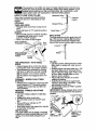
CAUTION:
Read and follow all
Safety Rules and Instructions
before operating this equipment
Sears, Roebuck and Co.,Hoffman Estates, IL 60179

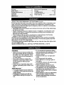
Warranty ............................. ;................... 2
Safety Rules ..................... :..................... 2
Product Specifications .......................... 4
Assembly ........................... _.................... 5
Operation ......................................... 3 & 8
Maintenance .................................. _...... 13
Service and Adjustments ...................... 15
Storage .......................................... 3 & 19
Troubleshooting .................................... 20
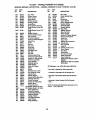
Illustrated Parts List .............................. 42
Parts Ordering ....................... Back Cover
LIMITED TWO YEAR WARRANTY ON CRAFTSMAN TILLER
For two (2) years from date of purchase, when this Craftsman Tiller is maintained, lubri-
cated, and tuned up according to the operating and maintenance instructions in the
owner's manual, Sears will repair free of charge any defect in material or workmanship.
This Warranty does not cover:
• Expendable items which become worn during normal use, such as tines, spark plugs,
air cleaners and belts.
• Repairs necessary because of opbrator abuse or negligence, including bent crank-
shafts and the failure to maintain the equipment according to the instructions con-
tained in the owner's manual.
• If this Craftsman Tiller is used for commercial or rental purposes, this Warranty
applies for onlythirty (30) days from the date of purchase.
Warranty service is available by returning the craftsman power mower to the nearest
sears service center/department in the united states. This warranty applies only while
this product is in use in the united states.
This Warranty gives you specific legal rights, and you may also have other rights which
vary from state to state.
SEARS, ROEBUCKAND CO., D/817WA, HOFFMAN ESTATES, IL 60179
TRAINING
• Read the Owner's Manual carefully. Be
thoroughly familiar with the controls and
the proper use of the equipment. Know
how to stop the unit and disengage the
controls quickly.
• Never allow children to operate the
equipment. Never allow adults to oper-
ate the equipment without proper
instruction.
• Keep the area of operation clear of all
persons, particulady small children, and
pets. ,,
PREPARATION
• Thoroughly inspect the area where the
6quipment is to be used and remove all
foreign objects.
• Disengage all clutches and shift into
neutral before starting the engine (mo-
tor).
• Do not operate the equipment without
wearing adequate outer garments. Wear
footwear that will improve footing on
slippery surfaces.
• Handle fuel with care; it is highly flam-
mable.
• Use an approved fuel container.
• Never add fuel to a running engine or
hot engine.
• Fill fuel tank outdoors with extreme care.
Never fill fuel tank indoors.
• Replace gasoline cap securely and
clean up spilled fuel before restarting.
• _Jse extension cords and receptacles as
specified by the manufacturer for all
units with electdc drive motors or electric
starting motors.
• Never attempt to make any adjustments
while the engine (motor) is running
(except where specifically recommend-
ed by manufacturer).
2

OPERATION
• Do not put hands or feet near'or under
rotating parts.
• Exercise extreme caution when operat-
ing on or crossing gravel drives, walks,
or roads. Stay alert for hidden hazards
or traffic. Do not carry passengers.
• After striking a foreign object, stop the
engine (motor), remove the wire from
the spark plug, thoroughly inspect the
tiller for any damage, and repair the
damage before restarting and operating
the tiller.
• Exercise caution to avoid slipping or
falling.
• If the unit should start to vibrate abnor-
mally, stop the engine (motor) and check
immediately for the cause. Vibration is
generally a warning of trouble.
• Stop the engine (motor) when leaving
the operating position.
• Take all possible precautions when leav-
ing the machine unattended. Disengage
the tines, shift into neutral, and stop the
engine.
• Before cleaning, repairing, or inspecting,
shut off the engine and make certain all
moving parts have stopped. Disconnect
the spark plug wire, and keep the wire
away from the plug to prevent accidental
starting. Disconnect the cord on electric
motors.
• Do not run the engine indoors; exhaust
fumes are dangerous.
• Never operate the tiller without proper
guards, plates, or other safety protective
devices in place.
• Keep children and pets away.
• Do not overload the machine capacity
by attempting to till too deep at too fast a
rate.
• Never operate the machine at high
speeds on slippery surfaces. Look
behind and use care when backing.
• Never allow bystanders near the unit.
• Use only attachments and accessories
approved by the manufacturer of the
tiller (such as wheel weights, counter-
weights, cabs, and the like).
• Never operate the tiller without good vis-
ibility or light.
• Be careful when tilling in hard ground.
The tines may catch in the ground and
propel the tiller forward. If this occurs,
let go of the handlebars and do not
restrain the machine.
MAINTENANCE AND STORAGE
• Keep machine; attachments, and
accessories in safe working condition.
• Check shear pins, engine mounting
bolts, and other bolts at frequent inter-
vals for proper tightness to be sure the
equipment is in safe working condition.
• Never store the machine with fuel in the
fuel _,nk inside a building where ignition
sources are present, such as hot water
and space heaters, clothes dryers, and
the like. Allow the engine to cool before
storing in any enclosure.
• Always refer to the operator's guide
instructions for important details if the
tiller is to be stored for an extended peri-
od.
_.CAUTION: Always disconnect spark
plug wire .and place wire where it cannot
contact spark plug in order to prevent acci-
dental starting when setting up, transport-
ing, adjusting or making repairs.
WARNING
The engine exhuast from this product con-
tains chemicals known to the State of
California to cause cancer, birth defects, or
other reproductive harm.

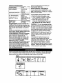
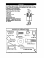
PRODUCT SPECIFICATIONS
1 !
-IORSEPOWER: 6.5.HP
)ISPLACEMENT: 12.48 CU. IN.
(266CO)
GASOLINE CAPACITY: 3 Quads
Unleaded Regular
OIL (API-SF/SG/SH): SAE 30
(Above 40°F)
CAPACITY: 19 oz.) SAE5W-30/10W-30
(Below 40°F)
SPARK PLUG : Champion RJ19LM
(GAP: .030") OR J19LM
Congratulations on your purchase of a
Craftsman Tiller. It has been designed, en-
gineered and manufactured to give you the
best possible dependability and perform-
ante.
Should you experience any problem_ you
cannot easily remedy, please contact your
nearest authorized Sears Service
Center/Department. We have competent,
well-trained technicians and the proper
tools to service or repair this unit.
Please read and retain this manual. The
instructions will enable you to assemble
and maintainyour tiller properly. Always
observe the SAFETY RULES.
Your new tiller has been assembled at the
factory with exception of those parts left
unassembled for shipping purposes. To
ensure safe and proper operation of your
tiller all parts and hardware you assemble
must be tightened securely.
Use the correct tools as necessary to
insure proper tightness.
MAINTENANCE AGREEMENT
A Sears Maintenance Agreement is avail-
able on this product. Contact your nearest
Sears store for details.
CUSTOMER RESPONSIBILITIES
• Read and observe the safety rules.
• Follow a regular schedule in maintain-
ing, caring for and using your tiller.
• Follow the instructions under the
"Customer Responsibilities" and "Stor-
age" sections of this Owner's Manual.
WARNING: This unit is equipped with an
internal combustion engine and should not
be used on or near any unimproved forest-
covered, brush-covered or grass covered
land unless the engine's exhaust system is
equipped with a spark arrcster meeting
applicable local or state laws (if any). If a
spark arrester is used, it should be main-
tained in effective working order by the
operator.
In the state of California the above is
required by law (Section 4442 of the
California Public Resources Code). Other
states may have similar laws. Federal
laws apply on federal lands. See your
Sears Authorized Service Center for spark
arrester. Refer to the Repair Parts section
of this manual for part number.
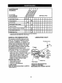
These accessories were available when the tiller was purchased. They are also avail-
able at most Sears Retail outlets and Service Centers. Most Sears Stores can order
repair parts for you when you provide the model number of your tiller.
ENGINE
TILLER PERFORMANCE
FUR_ENER I
TILLER MAINTENANCE
BELT TINES SHE_R pIN HAIRPIN CLIP
4

Your new tiller has been assembled at the factory with exception of those parts left
unassembled for shipping purposes. To ensure safe and proper operation of your tiller
all parts and hardware you assemble must be tightened securely. Use the correct tools
as necessary to insure proper tightness.
TOOLS REQUIRED FOR ASSEMBLY
A socket wrench set will make assembly
easier. Standard wrench sizes are listed.
(1) Utility knife
(1) Wire cutter
(t) Tire pressure gauge
(1) Screwdriver
(1) Pair of pliers
(1) 9/16" wrench
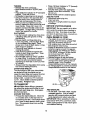
OPERATOR'S POSITION
When right or left hand is mentioned in
this manual, it means whenyou are in
the operating position (standing behind
tiller handles).
FRONT
LEFT
RIGHT
OPERATOR'S
POSITION
CONTENTSOF HARDWARE PACK
/IIIIIII/Y
(2) Handle Locks
(1) Carriage Bolt ,
3/8-16 UNC x I Gr. 5
121Ha,_,nc,,pst L ) )
_J"3/32x 1 x 11 Ga. '
°1 O
Extra Shear Pins & Clips
@
(1) Center Locknut
3/8-16 UNC
(1) Cable Clip
(1) Pivot Bolt
3/8-16 UNC Grade 5
(1) Handle Lock Lever
I
5

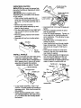
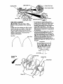
UNPACKING CARTON
_,CAUTION: Be careful of.exposed sta-
ples when handling or disposing of carton-
ing material.
IMPORTANT:When unpacl_ing and
assembling tiller, be careful not to stretch
or kink cables.
• While holding handle assembly, cut
cable ties securing handle assembly to
top frame. Let handle assembly rest on
tiller.
• Remove top frame of carton.
• Slowly ease handle assembly up and
place on top of carton.
• Cut down right hand front and right hand
rear corners of carton, lay side carton
wall down,
• Remove packing material from handle
assembly.
• Separate shift rod from handle asSem-
bly.
Shift Rod
Assembly
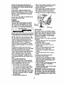
INSTALL HANDLE
• Insert one handle lock (with teeth facing
outward) in gearcase notch. (Apply
grease on smooth side of handle lock to
aid in keeping lock in place until handle
assembly is lowered into position.)
VIEWED FROM R,H. SIDE OF TILLER
Handle Assembly
rcase Notch
Handle Lock
'1
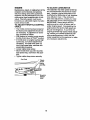
• G_asp handle assembly. Hold in "up"
position. Be sure handle lock remains in
gearcase notch. Slide handle assembly
into position.
• Rotate handle assembly down. Insert
rear cardage bolt first, with head of bolt
on L.H. side of tiller and loosely assem-
ble Iocknut.
6
,IW. ,_=,,_ --Hand e Assembly
f %..:,.>.,;_ .,,,J UP Position
_'_'_"J_'.,_'*.:.',,o Tighten handle lock
toho,°
Loosen Handle_Lock'_'__
Lever to Move . _"_--d_
• Insert pivot bolt in front part of plate and
tighten,
• Cut down remaining corners of carton
and lay panels flat.
• Lower the handle assembly. Tighten nut
on car,iage bolt so handle moves with
some resistance. This will allow for eas-
ier adjustment.
• Place flat washer on threaded end of
handle lock lever.
• Insert handle lock lever through handle
base and gearcase. Screw in handle
lock lever just enough to hold lever in
place.
• Insert second handle lock (with teeth
inward) in the slot of the handle base
(just inside of washer).
• Raise handle assembly to highest posi-
tion and securely tighten handle lock
lever by rotating clockwise. Leaving
handle assembly in highest position will
make it easier to connect shift rod.
: Handle Lock
Gearcase
\
Slot
Rear Cartddge
Bolt
Flat Washer
Handle Lock
Handle Base
Pivot Bolt
Locknut"

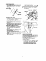
INSERTCABLECLIP
• Insert plastic cable clip into hole on the
back of handle column. Push cables
into clip.
Handle Column
Cables
Attach this end to shift lever
_"_Attach this EndTo shi" _ Shift Rod
Lever indicator
Hairpin Clip Shift Lever
ndicator
Shift Rod
Cable Clip
CONNECT SHIFT ROD
• Insert end of shift rod farthest from bend
into hole of shift lever indicator.
• Insert hairpin clip through hole of shift
rod to secure.
• Insert other end of shift rod into hole in
shift lever.
• Insert second hairpin clip through hole of
shift rod with bend of clip on rinht side.
REMOVE TILLER FROM CRATE.
• Adjust handle assemby to lowest posi-
tion. Be sure lock lever is tightened
securely.
• Make sure shift lever indicator is in "N"
(neutral) position.
• Tilt tiller forward by lifting handle.
Separate cardboard cover from leveling
shield.
• Rotate tiller handle to the dght and pull
tiller out of carton.
Shift Lever
Shift.od\ Lk
CHECK TIRE PRESSURE
The tires on your unit were overinflated at
the factory for shipping purposes. Correct
and equal tire pressure is important for
best tilling performance.
• Reduce tire pressure to 20 PSI.
HANDLE HEIGHT
• Handle height may be adjusted to better
suit. operator. (See "TO ADJUST HAN-
DLE HEIGHT" in the Service and
Adjustments section of this manual).
7

These symbols may appear on your Tiller or in literature supplied with the product.
Learn and understand their meaning.
CAUTION ENGIN_ ENGINE
TILLINO TILLING FOI_WARD NEUTRAL REVERSE ORWA_I_tG' ON OFF
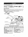
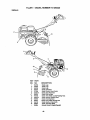
KNOW YOUR TILLER
READ THIS OWNER'S MANUALAND SAFETY RULES BEFORE OPERATING YOUR
TILLER.
Compare the illustrations with your tiller to familiarize yourself with the location of vari-
ous controls and adjustments. Save this manual for future reference.
Drive ControlBar
:Lever
Shift Lever Indicator
Dra!
Depth
Leveling
Outer Side Shield
Recoil
Starter
Handle
MEETS ANSI SAFETY REQUIREMENTS
Our tillers conform to the safety standards of the American National Standards Institute.
DRIVE CONTROL BAR - Used to engage
tines.
DEPTH STAKE - Cont!_ols depth at which
tiller will dig.
OUTER SIDE SHIELD - Adjustable to pro-
tect small plants from being buried.
THROTTLE CONTROL - Used to control
engir, e speed.
LEVELING SHIELD - Levels tilled soil.
SHIFT LEVER - Used to shift transmission
gears.
SHIFT LEVER INDICATOR - Shows which
gear the transmission is in.
RECOIL STARTER HANDLE - Used to
start the engine.
DRAG STAKE - Controls forward speed.
In forward rotating till mode.
8

Theoperationofany tiller can result in foreign objects thrown into the eyes,
which can result in severe eye damage. Always wear safety glasses or eye
shields before starting your tiller and while tilhng. We recommend a wide
vision safety maskover spectacles or standard safety glasses.
HOW TO USE YOUR TILLER
Know how to operate all controls before
add!ng fuel and oil or attempting to start
engine.
STOPPING
TINES AND DRIVE
• Release drive control bar to stop move-
ment.
• Move shift lever to "N" (neutral) position.
ENGINE
• Move throttle control to =STOP" position.
If equipped with stop switch, move
switch to "STOP" position.
• Never use choke to stop engine.
Drive Control Bar _ .....
"ENGAGED" Position- _..--::;/_ ._n=nr
D,ve
"DISENGAGED" _ "_ _'_ \
Position T_r_t_loe; _. _ 1
TINE OPERATION - WITH WHEEL
DRIVE
• Always release drive control bar before
moving shift lever into another position.
• "line movement is achieved by moving
shift lever to either the counter rotating
(_;) till position or the forward rotating
(_) till position and engaging drive con-
trol bar.
FORWARD - WHEELS ONLY/TINES
STOPPED
• Release drive control bar and move shift
lever indicator to "F" (forward) .p,osition.
Engage drive control bar and tiller will
move forward,
REVERSE - WHEELS ONLY/TINES
STOPPED
• DO NOT STAND DIRECTLY BEHIND
TILLER.
• Release the drive control bar.
• Move throttle control to "SLOW" posi-
tion. ,_
• Move shift lever indicator to =R"
(reverse) position,
• Hold ddve control bar against the handle
to start tiller movement.
DEPTH STAKE
The depth stake can be raised or lowered
to allow you more versatile tilling and culti-
vating, or to more easily transport your
tiller.
ShallowestTilling
""" Transport
Position
Deepest Tilling .------
Depth Stake _-_
DRAG STAKE
The drag stake should be raised when till-
ing in the counter rotating (_)till position.
The drag stake should be lowered when
tilling in the forward rotating (_)till position.
Lowered_
-.--........._
Raised
TILLING
• Use the counter rotating tine drive when
tilling hard or rockey soil, virgin ground,
or sod.
i elease depth and drag stake pins. Pull
the depth stake up for increased tilling
depth. Raise the drag stake. Place prop-
er pin in hole of depth stake or drag
stake to lock in position.
Place shift lever indicator in counter
rotating till position.
• Holplthe drive control bar against the
handle to start tilling movement. Tines
and wheels will both turn,
• Move throttle control to =FAST" position
for deep tilling,
IMPORTANT: Always release drive control
bar before moving shift lever into another
position.
=Locked" Position
Nut
=B"
Outer / =RELEASED"
Side Shield "A". Position
9

TURNING
• Release the drive control bar.
• Move throttle control to =SLOW" posi-
tion.
• Place shift lever indicator in "F_ (forward)
position. Tines will not turn.
: Lift handle to raise tines out of ground.
Swing the handle in the opposite direc-
tion you wish to turn, bein'g careful to
keep feet and legs away from tines.
• Whenyou have completed your turn-
around, release the drive control bar and
lower handle. Place shift lever in till
position and move throttle control to de-
sired speed. To begin tilling, hold drive
control bar against the handle.
CULTIVATING
• Use the forward rotating tins drive.when
cultivating, tilling soft ground or tilling
pre-tilled soil.
• Release depth and drag stake pins.
Lower drag stake. Pull the depth §take
up for increased tilling depth. Place
proper pin in hole of depth stake or drag
stake to lock in position.
• Place shift lever indicator in forward
rotating till position.
• Hold the drive control bar against the
handle to start tilling movement. Tines
and wheels will both turn.
• Move throttle control to "FAST" position
for deep tilling. To cultivate, throttle con-
trol can be set at any desired speed,
depending on how fast or slow you wish
to cultivate.
• Always lower the drag stake when using
the forward rotating tins drive.
OUTER SIDE SHIELDS
The back edges of the outer side shields
are slotted so that the shields can be
raised for deep tilling and lowered for shal-
low tilling to protect small plants from
being buried. Loosen nut =A" in slot and
nut =l_". Move shield to desired position
(both sides). Retighten nuts.
TO TRANSPORT
_CAUTION: Before lifting or transport-
ing, allow tiller engine and muffler to cool.
Disconnect spark plug wire. Drain gaso-
line from fuel tank.
AROUND THE YARD
Release the depth s_takepin. Move the
dr.pth stake down to the top hole for
transporting the tiller. Place depth stake
pin in hole of depth stake to lock in posi-
tion. This prevents tines from scuffing
the ground.
• Place '.;hi_ lever indicator in "F" (forward)
position for transporting.
• Hold the drive control bar against the
handle to start tiller movement. Tines
will not turn.
• Move throttle control to desired speed.
AROUND TOWN
• Disconnect spark plug wire.
• Drain fuel tank.
• Transport in upright position to prevent
oil leakage.
BEFORE STARTING ENGINE
IMPORTANT: Be very careful not to allow
dirt to enter the engine when checking or
adding oil or fuel. Use clean oil and fuel
and store in approved, clean, covered con-
tainers, use clean fill funnels.
CHECK ENGINE OIL LEVEL
• The engine in your unit has been
shipped, from the factory, already filled
with SAE 30 summer weight oil.
With engine level, clean area around oil
filler plug and remove plug.
Engine oil should be to point of overlow-
ing when engine is level For approxi-
mate capacity see "PRODUCT SPECI-
FICATIONS" on page 4 of this manual.
All oil must meet A.P.I. Service
Classification SF, SG or SH.
Reinstall engine oil cap and tighten
For cold weather operation you should
change oil for easier starting (See oil
viscosity chart in the Customer
Responsibilities section of this manual).
To change engine oil, see the Customer
Responsibilities section in this manual.
ADD GASOLINE
• Fill fuel tank. Use fresh, clean, regular
unleaded gasoline. (Use of leaded
gasoline will increase carbon and lead
oxide deposits and reduce valve life.
IMPORTANT: When operating in tempera-
tures below 40°F (4°C), use fresh, clean,
winter grade gasoline to help insure good
cold weather starting.
10

WARNING:Experienceindicatesthatalco-
h01blendedfuels(calledgasoholorusing
ethanolormethanol)canattractmoisture
whichleadsto separationandformation of
acids during storage. Acidic gas can dam-
age the fuel system of an engine while in
storage. To avoid engine problems, the
fuel system should be emptied before
storage of 30 days or longer. Drain the
gas tank, start the engine and let it run
until the fuel lines and carburetor are
. empty. Use fresh fuel next season. See
Storage section of this manual for addition-
al information. Never use engine or carbu-
retor cleaner products in the fuel tank or
P_rcmanent damage may occur.
AUTION: Fill to within 1/2 inch of top
of fuel tank to prevent spills and to allow
for fuel expansion. If gasoline is acciden-
tally spilled, move machine away from
area of spill. Avoid creating any source of
ignition until gasoline vapors have disap-
peared.
o not overfill. Wipe off any spilled oil or
fuel. Do not store, spill or use gasoline
near an open flame.
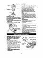
TO START ENGINE
._,CAUTION: drive control bar in
pep
DISENGAGED position when starting en-
gWine,
hen starting engine for the first time or if
engine has run out of fuel, it will take extra
pulls of the recoil starter to move fuel from
the tank to the engine.
• Make sure spark plug wire is properly
connected.
• Move shift lever indicator to "N" (neutral)
position.
• Place throttle control in "FAST" position.
• Turn fuel shut-off valve 1/4 turn to OPEN
position.
• Move choke control to CHOKE position.
• Grasp recoil starter handle with one
hand and grasp tiller handle with other
hand. Pul/rope out slowly until engine
reaches start of compression cycle (rope
will pull slightly harder at this point).
Fuel shut-off Choke controls
Rewind start_
• Pull recoil starter handle quickly. Do not
let starter handle snap back against
starter.
• If engine fires but does not start, move
choke control to half choke position, Pull
recoil starter handle until engine starts.
• When engine starts, slowly move choke
control to "RUN" position as engine
warms up,
NOTE A warm engine requires less chok-
ing starting.
• Move throttle control to desired running
position.
• Allow engine to warm up for a few min-
utes before engaging tines.
NOTE: If at a high altitude (3000 feet) or in
cold temperatures (below 40°F), the carbu-
retor fuel mixture may need to be adjusted
for best engine pertomrance. See 'q-O
ADJUST CARBURETOR in the Service
and Adjustments section of this manual.
NOTE: If engine does not start, see trou-
bleshooting points.
TILLING HINTS
_CAUTION: Until you are accustomed to
handling your tiller, start actual field use
with thro_le in slow positio.n.(mid-way
between FAST" and "IDLE ).
• Tilling is digging into. turning over, and
breaking up packed soil before planting.
Loose, unpacked soil helps root growth.
Best tilling depth is 4" to 6". A tiller will
also clear the soil of unwanted vegeta-
tion. The decomposition of this veg-
etable matter enriches the soil.
Depending on the climate (rainfall and
wind), it may be advisable to till the soil
at the end of the growing season to fur-
the. condition the soil.
• Soil conditions are important for proper
tillinQ. Tines will not readily penetrate
dry,'hard soil which may contribute to
excessive bounce and difficult handling
of your tiller. Hard soil should be mois-
tened before tilling; however, extremely
wet soil will "ball-up" or clump during till-
ing. Wait until the soil is less wet in order
to achieve the best results. When tilling
in the fall, remove vines and long grass
to prevent them from wrapping around
the tne shaft and sow ng your tilling
operation.
• You will find tilling much easier if you
leave a row untilled between passes.
Then go back between tilled rows.There
are two reasons for doing this. First,
wide turns are much easier to negotiate
than about-feces. Second, the tille=
won't be pulling itself, and you, toward
the row next to it.
11

• Do not lean on handle..This takes
weight off the wheels andreduces rac-
tion. To get through a ,rea!ly tough sec-
tion of sod or hard ground, apply upward
pressure on handle or lower the depth
stake.
CULTIVATING
Cultivating is destroying the weeds '
between rows to prevent them from rob-
bing nourishment and moisture from the
plants. At the same time, breaking up the
upper layer of soil crust will help retain
moisture in the soil. Best digging depth is
1"to 3" (2.5-7.5 cm). Lower the outer side
shields to protect small plants from being
buried,
• Cultivate up and down the rows at a
speed which will allow tines to uproot
weeds and leave the ground in rough
condition, promoting no further growth of
weeds and grass.
• Do not lean on handle, this takes weight
off the wheels, reduces traction, and
may cause the tiller to skip over the
ground.
• Always lower the drag stake when
using the forward rotating tine drive.
©
©
©
©
A
0101010
0101010
0101010
0101010
_J _J
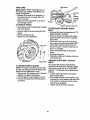
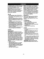
TINE SHEAR PINS
The tine assemblies on your tiller are
secured to the tine shaft with shear pins
(See "FINE REPLACEMENT" in the
Service and Adjustments section of this
manual).
If the tiller is unusually overloaded or
jammed, the shear pins are designed to
break before internal damage occurs to
the transmission.
• If shear pin(s) break, replace only with
those shown in the Repair Parts section
of this manual.
12

WW
SCHEDULE
FI,,,No, °s /. 7'2Z
ya ,, ERV,OE
Check Engine Oil Level l/ k/
Change EngineOil t_,2
Oil Pivot Points
Inspect Spark Arrester / Muffler t4/
Inspect Air Screen IV/
Clean or Replace Air Cleaner Cartridge I_ 2
Clean Engine Cylinder Fins V /
Replace Spark Plug I_
I - Change more often when operatingut',dera lies W load o_in high an'_nt temperatures.
2 - Senfce mo_e often when operating inOktyor duStyconditions,
GENERAL RECOMMENDATIONS
The warranty on this tiller does not cover
items that have been subjected to opera-
tor abuse or negligence. To receive full
value from the warranty, the operator must
maintain tiller as instructed in this manual.
Some adjustments will need to be made
periodically to propedy maintain your tiller.
All adjustments in the Service and
Adjustments section of this manual should
be checked at least once each season.
• Once a year you should replace the
spark plug, clean or replace air filter, and
check tines and belts for wear. A new
spark plug and clean air filter assure
proper air-fuel mixture and help your
engine run better and last longer.
BEFORE EACH USE
• Check engine oil level.
• Check tine operation.
• Check for loose fasteners.
LUBRICATION
Keep unit well lubricatedi(Sea "LtJBRICA-
TION CHART").
LUBRICATION CHART
* Idler Bracket
*Throttle Control
_: Drag
_ Stake Pin
.l_'-"-" * Depth
_;_'_,._ Stake Pin
t_ * Leveling
#_ Shield
v I Hinges
\ * Wheel Hub
* SAE 30 OR 10W-30 MOTOR OIL
** REFER TO CUSTOMER
RESPONSIBILITIES "ENGINE" SECTION
13

Disconnectsparkplugwirebeforeper-
forminganymaintenance(exceptcarbure-
toradjustment)topreventaccidentalstart-
ingofengine.
Prevent fires! Keep the engine free of
grass, leaves, spilled oil, or fuel. Remove
fuel from tank before tipping unit for main-
tenance. Clean muffler area of all grass,
dirt, and debris.
Do not touch hot muffler or cylinder fins as
contact may cause bums.
ENGINE
LUBRICATION
Use only high quality detergent oilrated
with API service classification SF, SG or
SH. Select the oil's SAE viscosity grade
according to your expected temperature.
SAE VISCOSITY GRADES
_C -30' .20" .10" 20'
TEMPERATURE RANGE ANI"_IPATED BEFORE NEXT OIL CHANGE
NOTE: Although multi-viscosity oils (5Wo
30, 10W-30, etc.) improve starting in cold
weather, these multi-viscosity oils will
result in increased oil consumption when
used above 40°F (4°C). Check your
engine oil level more frequently to avoid
possible engine damage from running low
on oil.
Change the oil after every 50 hours of
operation or at least once a year if the tiller
is not used for 50 hours in one year.
Check the crankcase oil level before start-
ing the engine and after each five (5)
hours of continuous use. Add SAE 30
motor oil or equivalent. Tighten oil t;ller
plug securely each time you check the oil
level.
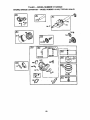
TO CHANGE ENGINE OIL
Determine temperature range expected
before oil change. All oil must meet API
service classification SF, SG or SH.
• Be sure tiller is on level surface.
• Oil will drain more 'freely when warm.
• Use a funnel to prevent oil spill on tiller,
and catch oil in a suitable container.
• Remove oil drain plug. Be careful not to
allow dirt to enter the engine. For easier
removal of plug use 7/16 12 Pt. socket
with extension.
• "rip tiller forward to drain oil.
• After oil h_s drained completely, replace
oil drain plug and tighten securely.
• RemOve oil fill plug.
• Refill engine with oil through oil fill tube.
See "CHECK ENGINE OIL LEVEL" in
the Operation section of this manual.
• Replace oil fill plug and tighten securely.
Oil
drainPlug
Oil Fill Plug
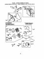
AIR FILTER
Your engine will not run properly using a
dirty airfllter. Clean the foam pre-cleaner
after every 50 hours of operation or every
season. Service paper cartridge every
100 hours of operation or every season,
whichever occurs first.
Service air cleaner more often under dusty
conditions.
• Remove knob and cover. Lift air cleaner
assembly oft stud.
TO SERVICE PRE-CLEANER
• Remove foam pre-cleaner from air
cleaner cover.
• Wash it in liquid detergent and water.
• Squeeze it dry in a clean cloth.
• If verydirty or damaged, replace pre-
cleaner;
• Reinstall pre-cleaner into air cleaner
cover.
• Reinstall cover and secure knob.
TO SERVICE CARTRIDGE
• Carefully remove cartridge to prevent
debns from entering carburetor. Clean
base carefully to prevent debris from
entering carburetor.
• Clean cartridge by tapping gently on flat
surface. If very dirty or damaged,
replace cartridge.
• Reinstall cartridge, cover with pre-clean-
er and secure with knob.
IMPORTANT; Petroleum solvents, such
as kerosene, are not to be used to clean
the cartridge. They may cause deteriora-
tion of the cartridge. Do not oil cartridge.
Do not use pressurized air to clean or dry
cartddge.
14

Cover_
COOLING SYSTEM
Your engine is air cooled. For proper
engine performance and long life keep
your engine clean.
• Clean airscreen frequently using a stiff-
bristledbrush.
• Keep cylinder fins, levers, and linkage
free of dirtand chaff.
Muffler
MUFFLER
Do not operate tiller without muffler. Do not
tamper with exhaust system. Damaged
mufflers or spark arresters could create a
fire hazard. Inspect periodically and re-
place if necessary. If your engine is
equipped with a spark arrester screen
assembly, remove every 50 hours for
cleaning and inspection, Replace if dam-
aged.
SPARK PLUG
Replace spark plugs at the beginning of
each tilling season or after every 50 hours
of use, whichever comes first. Spark plug
type and gap setting is shown in "PROD-
UCT SPECIFICATIONS" on page 4 of this
manual.
TRANSMISSION
Your transmission is sealed and will only
require lubrication if serviced.
CLEANING
• Clean engine, wheels, finish, etc. of all
foreign matter.
• Keep finished surfaces and wheels free
of all gasoline, oil, etc.
• Protect painted surfaces with automotive
type wax.
We do not recommend using a garden
hose to clean your unit unless the muffler,
air filter and carburetor are covered to
keep water out. Water in engine can result
in a shortened engine life.
_.CAUTION: Disconnect spark plug wire
from spark plug and place wire where it
cannot come into contact with plug.
TILLER
TO ADJUST HANDLE HEIGHT
Select handle height best suited for your
tilling conditions. Handle height will be dif-
ferent when tiller digs into soil.
• First loosen handle lock lever.(Do not
loosen too much or handle locks may
fall out.) '_
• Handle can be positionedat different
, settings between "HIGH" and "LOW"
positions.
• Retighten handle lock lever securely
after adjusting.
Handle (Low)
Position
Handle (High) Position
Handle Lock Lever
15

TIRE CARE
_.CAUTION: When mouhting tires, un-
less beads are seated, overinflation can
cause an explosion.
• Maintain 20 pounds of air pressure. If
tire pressures are not equal, tiller will
pull to one side.
• Keep tires free of gasoline or oil which
can damage rubber.
TO REMOVE WHEEL
• Place blocks under transmissionto keep
tillerfrom tipping.
• Remove hairpin clipand clevis pin from
wheel.
• Remove wheel and tire.
• Repair tire and reassemble.
is Pin
".1
HairpinC/lip
TO REMOVE BELT GUARD
NOTE: For ease of removal, remove hair-
pin clip and clevis pin from left wheel. Pull
wheel out from tiller about 1 inch.
• Remove two (2) screws, one (1) nut and
washer from side of belt guard.
• Pull belt guard out and away from unit.
• Replace belt guard by reversing above
procedure.
_lt Gu_
/ _m,_3_-"_.!_ _Hex Nut
I_-_t_$_,_ and
W her
X_"_ 3\ (Located
_ _ '_--------------_\ Behind
screws
Hairpin Clip and Clevis Pin
TO REPLACE GROUND DRIVE
BELT
• Remove belt guard as described in =TO
REMOVE BELT GUARD",
• Remove old belt by slipping off engine
pulley first then remove from transmis-
sion pulley.
• Place new belt in groove of transmis-
sion pulley and into engine pulley. BELT
MUST BE IN GROOVE ON TOP OF
IDLER PULLEY. NOTE POSITION OF
BELT TO GUIDES.
• Check belt adjustment as described
below.
• Replace belt guard.
• Reposition wheel and replace clevis pin
and hairpin clip.
GROUND DRIVE BELT ADJUST-
MENT
For proper belt tension, the extension
spring should have about 5/8 inch stretch
when drive control bar is in =ENGAGED"
position. This tension can be attained as
follows;
• Loosen cable clip screw securing the
drive control cable.
• Slide cable forward for less tension and
rearward for more tension until about 5/8
inch stretch is obtained while the drive
control bar is engaged.
• Tighten cable clip screw securely.
16

Engine_
t ,
ipScrew
}dve Control Cable
Idler Pulley
Transmission Pulley
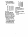
TINE REPLACEMENT •
A, CAUTION: Tines are sharp. Wear
gloves or other protection when handling
tines.
A badly worn tine causes your tiller to work
harder and dig more shallow. Most impor-
tant, worn tines cannot chop and shred
organic matter as effectively nor bury it as °
deeply as good tines. Atine this worn
needs to be replaced.
New Tine
/2
Worn Tine
CounterTine
Rotation
Sharp
'1
Extension Spring
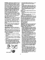
To maintain the superb tilling perfor-
mance of this machine the tines should
be checked for sharpness, wear, and
bending, particulady the tines which are
next to the transmission. If the gap
between the tines exceeds 3-1/2 inches
they should be replaced or straightened
as necessary.
For tines that are slightly worn, the bolt-
ed tine and hub assemblies can be
switched between sides to continue till-
ing in the same tilling mode. If tilling in a
different mode is desired then the bolted
tine and hub assemblies should be
switched back to their original side so
that the tine edge with the least wear will
be used.
\ transmission /
I I I
I I
I I
3-112"Max , '
, ---t I----
17

ENGINE
Maintenance, repair, or repracement of the
emission control devices and systems,
which are being done at thQ customers
expense, may be performed by any non-
road engine repair establishment or indi-
vidual. Warranty repairs must be per-
formed by an authorized engine manufac-
turer's service outlet.
TO ADJUST THROTTLE CONTROL
CABLE
• The throttle Control has been preset at
the factory and adjustment should not
be necessary. If adjustment is neces-
sary, proceed as follows:
• With engine not running, move remote
throttle control lever to =FAST" position.
• If throttle lever on engine touches high
speed stop, no further adjustment js
necessary. If throttle lever does not
touch high speed stop, continue with
adjustment procedure.
• Loosen cable clamp screw.
• Move throttle lever up until it touches
high speed stop, and hold in this posi-
tion.
• Tighten cable clamp screw securely.
FuelTank
/ Clamp
, Screw
TO ADJUS T CARBURETOR
The carburetor has been preset at the fac-
tory and' adjustment should not be neces-
sary. However, engine performance can
be affected by differences in fuel, tempera-
ture, altitude or load. If the carburetor
does need adjustment, contact your near-
est authorized service center/department
IMPORTANT: Never tamper with the
engine governor, which is factory set for
proper engine speed. Overspeeding the
engine above the factory high speed set-
ting can be dangerous. If you think the
engine-governed high speed needs adjust-
ing, contact your nearest authorized ser-
vice center/department, which has the
proper equipment and experience to make
any necessary adjustments.
Governor
Control
Lever
18

Immediately prepare your tiller for storage
at the end of the season or ifthe unit will
not be used for 30 days or more.
A_,CAUTION: Never store the tiller with
gasoline in the tank inside a building
where fumes may reach an open flame or
spark. Allow the engine to cool before
storing in any enclosure.
TILLER
• Clean entire tiller (See =CLEANING" in
the Customer Responsibilities section of
this manual).
• Inspect and replace belts, if necessary
(See belt replacement instructions in the
Service and Adjustments section of this
manual).
• Lubricate as shown in the Customer
Responsibilities section of this manual.
• Be sure that all nuts, bolts and screws
are securely fastened. Inspect moving
parts for damage, breakage and wear.
Replace if necessary.
• Touch up all rusted or chipped paint sur-
faces; sand lightly before painting.
ENGINE
FUEL SYSTEM
IMPORTANT: It is important to prevent
gum deposits from forming in essential fuel
system parts such as the carburetor, fuel
filter, fuel hose, or tank during storage.
also, experience indicates that alcohol
blended fuels (called gasohol or using
ethanol or methanol) can attract moisture
which leads to separation and formation of
acids during storage. Acidic gas can dam-
age the fuel system of an engine while in
storage.
• Drain the fuel tank.
• Start the engine and let it run until the
fuel lines and carburetor are empty.
• Never use engine or carburetor cleaner
products in the fuel tank or permanent
damage may occur.
• Use fresh fuel next season.
NOTE: Fuel stabilizer is an acceptable
alternative in minimizing the formation of
fuel gum deposits during storage. Add sta-
bilizer to gasoline in fuel tank or storage
container. Always follow the mix ratio
found on stabilizer container. Run engine
at leP_t 10 minutes after adding stabilizer
to allow the stabilizer to reach the carbure-
tor. Do not drain the gas tank and carbu-
retor if using fuel stabilizer.
ENGINE OIL
Drain oil (with engine warm) and replace
with clean oil. (See =ENGINE" in the
Customer Responsibilities section of this
manual).
CYLINDER(S)
• Remove spark plug,
• Pour 1 ounce (29 ml) of oil through
spark plug hole into cylinder,
• Pull starter handle slowly several times
to distribute oil.
• Replace with new spark plug,
OTHER
• Do not store gasoline from one season
to another.
• Replace your gasoline can if your can
starts to rust. Rust and/or dirt in your
gasoline will cause problems.
• If possible, store your unit indoors and
cover it to give protection from dust and
d_rt.
• C_ver your unit with a suitable protective
covP.rthat does not retain moisture. Do
not'use plastic. Plastic cannot breathe
which allows condensation to form and
will cause your unit to rust.
IMPORTANT: Never cover tiller while
engine and exhaust areas are still warm.
19

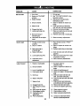
PROBLEM
Will not start
Hard to start
Loss of power
CAUSE
I
1. Out of fuel.
2. Engine not"CHOKED"
properly.
3, Engine flooded.
4. Dirty air cleaner.
5. Water in fuel.
6. Clogged fuel tank.
7. Loose spark plug wire.
8. Bad spark plug or
improper gap.
9. Carburetor o_t of adjust-
ment.
1. Throttle control not set
propedy.
2. Dirtyair cleaner.
3. Bad spark plugor
impropergap.
4. Stale or dirtyfuel.
5. Loosesparkplug wire.
6. Carburetoroutof.
adjustment.
1. Engine is overloaded.
2. Dirtyair cleaner.
3. Lowoil level/dirtyoil.
4. Faultyspark plug.
5. Oil in fuel.
6. Stale or dirtyfuel.
7. Water in fuel.
8. Clogged fuel tank.
9. Spark plug wire loose.
wire.
10. Dirtyengineair screen.
11. Dirty/cloggedmuffler.
12. Carburetoroutof
adjustment.
13. Poor compression.
20
CORRECTION
1. Fill fuel tank.
2. See _1"OSTART ENGINE" in.the
Operation section.
3. Wait several minutesbefore
attemptingto start.
4, Clean or replace air Cleanercar
tridge,
5. Drain fuel tank and carburetor,
and refilltank with fresh gasoline.
6. Remove fuel tank and clean.
7. Make sure spark plug wire is seat
ed propedyonplug,
8. Replace spark plug or adjust gap.
9. Make necessary adjustments.
2.
3.
4.
5.
6.
1,
2.
3.
4.
5.
6.
7.
8.
9.
10.
11.
12.
13.
Place throttle controlin "FAST"
position,
Clean or replaceair cleaner car
tridge.
Replace spark plug or adjustgap.
Drain fuel tank and refillwith fresh
gasoline•
Make sure spark plug wire isseat
ed properlyon plug.
Make necessary adjustments,
Set depth stake for
shallowertilling.
Clean or replace air cleaner car
tridge.
Check oillevel/change oil.
Clean and regap or change spark
plug.
Drain and clean fuel tank and
refill, and clean carburetor.
Drain fuel tank and refillwith fresh
gasoline.
Drain fuel tank and carburetor,
and refilltankwith fresh gasoline.
Remove fuel tank and clean.
Connect and tightenspark plug
Clean engine air screen.
Clean/replace muffler.
Make necessary adjustments.
Contactan authodzed Sears
Service Center/Department.
Page is loading ...
Page is loading ...
Page is loading ...
Page is loading ...
Page is loading ...
Page is loading ...
Page is loading ...
Page is loading ...
Page is loading ...
Page is loading ...
Page is loading ...
Page is loading ...
Page is loading ...
Page is loading ...
Page is loading ...
Page is loading ...
-
 1
1
-
 2
2
-
 3
3
-
 4
4
-
 5
5
-
 6
6
-
 7
7
-
 8
8
-
 9
9
-
 10
10
-
 11
11
-
 12
12
-
 13
13
-
 14
14
-
 15
15
-
 16
16
-
 17
17
-
 18
18
-
 19
19
-
 20
20
-
 21
21
-
 22
22
-
 23
23
-
 24
24
-
 25
25
-
 26
26
-
 27
27
-
 28
28
-
 29
29
-
 30
30
-
 31
31
-
 32
32
-
 33
33
-
 34
34
-
 35
35
-
 36
36


Craftsman 917.293300 User manual
- Category
- Mini tillers
- Type
- User manual
Ask a question and I''ll find the answer in the document
Finding information in a document is now easier with AI
Related papers
Other documents
-
Poulan 410241 User manual
-
 Poulan Pro PPCRT14 Owner's manual
-
 Poulan Pro PPCRT17 Owner's manual
-
Jonsered J208D17 User manual
-
Poulan Pro RT900 User manual
-
 Poulan Pro HDF900 Owner's manual
-
 Poulan Pro HDF900 User manual
-
-
-
Western Spinner Leveling Kit #95477 Installation guide


