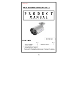
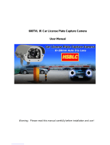
ECZ260

EverFocus ECZ260, EZ550 User manual

  • Hello! I am an AI chatbot trained to assist you with the EverFocus ECZ260 User manual. I’ve already reviewed the document and can help you find the information you need or explain it in simple terms. Just ask your questions, and providing more details will help me assist you more effectively!
  • What type of CCD sensor does the EverFocus ECZ260 camera use?
    What is the maximum resolution that the ECZ260 camera can output?
    What lens options are available for the ECZ260 camera?
    Does the ECZ260 camera have night vision capabilities?
    How can the ECZ260 camera be controlled remotely?
Operation Instruction
1
1
/
/
3
3
C
C
C
C
D
D
P
P
o
o
l
l
e
e
s
s
t
t
a
a
r
r
T
T
r
r
u
u
e
e
D
D
a
a
y
y
/
/
N
N
i
i
g
g
h
h
t
t
W
W
e
e
a
a
t
t
h
h
e
e
r
r
p
p
r
r
o
o
o
o
f
f
I
I
R
R
C
C
a
a
m
m
e
e
r
r
a
a
w
w
i
i
t
t
h
h
6
6
~
~
5
5
0
0
m
m
m
m
L
L
e
e
n
n
s
s
a
a
n
n
d
d
R
R
S
S
4
4
8
8
5
5
C
C
o
o
n
n
t
t
r
r
o
o
l
l
E
E
Z
Z
5
5
5
5
0
0
Volume
1
EverFocus
2
EVERFOCUS ELECTRONICS CORPORATION
P/N: MZ55G00200_Ver. B
Operation Instruction
© 2008 EverFocus Electronics Corp
Please read this manual first for correct installation and operation. This manual should be retained
for future reference. The information in this manual was current when published. The
manufacturer reserves the right to revise and improve its products. All specifications are therefore
subject to change without notice.
All rights reserved. No part of the contents of this manual may be reproduced or transmitted in any
form or by any means without written permission of the EverFocus Electronics Corporation.
3
Precautions
1. Do not place any object on top of the cover.
2. Be careful when handling the camera, do not drop it or subject it to strong shock or
vibration to prevent any damages to it. Do not disassemble it or place it on an unstable
base.
3. Install the camera away from TV, radio transmitter, magnet, electric motor, transformer,
audio speakers because the magnetic fields generate from above devices will distort the
video image.
4. Install the camera away from stoves, or other heat generating devices as the high
temperature could cause deformation, discoloration or other damages of the camera. Install
the camera at where the temperature range will stay between -40°C to 50°C (-40°F to
122°F).
5. Never aim the camera at the sun or other extremely bright objects whether it is in use or
not.
6. Do not touch the surface of CCD sensor by hand directly. Use a soft cloth to remove the
dirt from the camera body. Use lens tissue or a cotton tipped applicator and ethanol to
clean the CCD sensor and the camera lens. When the camera is not in use, put the cover
cap on the lens mount.
7. All warnings on the products and in the operating instructions should be adhered to.
8. Do not use attachments not recommended by the appliance manufacturer as they may
cause hazards.
9. Do not allow anything to rest on the power cord. Do not locate this appliance where the
cord will be abused by persons walking on it.
10. Do not overload wall outlets and extension cords as this can result in fire or electric shock.
11. Never push objects of any kind into his appliance through cabinet slots as they may touch
dangerous voltage points or short out parts that could result in fire or electric shock.
12. Refer all work related to the installation of this product to qualified service personnel or
system installers.
4
Federal Communication Commission Interference
Statement
This equipment has been tested and found to comply with the limits for a Class B digital device,
pursuant to Part 15 of the FCC Rules. These limits are designed to provide reasonable
protection against harmful interference in a residential installation. This equipment generates,
uses and can radiate radio frequency energy and, if not installed and used in accordance with the
instructions, may cause harmful interference to radio communications. However, there is no
guarantee that interference will not occur in a particular installation. If this equipment does
cause harmful interference to radio or television reception, which can be determined by turning
the equipment off and on, the user is encouraged to try to correct the interference by one of the
following measures:
- Reorient or relocate the receiving antenna.
- Increase the separation between the equipment and receiver.
- Connect the equipment into an outlet on a circuit different from that to which the
receiver is connected.
- Consult the dealer or an experienced radio/TV technician for help.
FCC Caution: Any changes or modifications not expressly approved by the party responsible
for compliance could void the user's authority to operate this equipment.
This device complies with Part 15 of the FCC Rules. Operation is subject to the following two
conditions: (1) This device may not cause harmful interference, and (2) this device must accept
any interference received, including interference that may cause undesired operation.
5
Table of Contents
1.1 Features ....................................................................................................................................... 1
1.2 Accessory Parts List .................................................................................................................... 2
1.3 Specifications ............................................................................................................................... 3
1.4 Dimensions ................................................................................................................................... 4
1.5 Camera Component Description .................................................................................................. 6
1.6 Back Panel Layout ....................................................................................................................... 7
1.7 Related Products .......................................................................................................................... 8
2.1 Wiring and Mounting ................................................................................................................... 13
2.2 Adjusting Camera Position ......................................................................................................... 18
2.3 Adjusting Lens ............................................................................................................................ 19
2.3.1 Lens Setting .................................................................................................................... 19
2.4 Keyboard Connection (Optional) ................................................................................................ 20
3.1 Control Key General Operation Guide........................................................................................ 21
3.2 RS485 ID & Baud Rate Setting ................................................................................................... 23
3.3 OSD Menu Setup ......................................................................................................................... 26
3.3.1 LENS ................................................................................................................................ 26
3.3.2 SHUTTER ........................................................................................................................ 26
3.3.3 WHITE BALANCE control ................................................................................................. 28
3.3.4 BACKLIGHT ..................................................................................................................... 28
3.3.5 AGC (Auto Gain Control) .................................................................................................. 29
3.3.6 DNR (Dynamic Noise Reduction) ..................................................................................... 29
3.3.7 SENS-UP .......................................................................................................................... 30
3.3.8 SPECIAL ........................................................................................................................... 31
3.3.8.1 CAMERA ID ........................................................................................................... 31
3.3.8.2 COLOR ADJ ........................................................................................................... 32
3.3.8.3 SYNC ..................................................................................................................... 33
3.3.8.4 MOTION DETECTION ............................................................................................ 33
3.3.8.5 PRIVACY ............................................................................................................... 35
3.3.8.6 MIRROR ................................................................................................................. 37
3.3.8.7 SHARPNESS .......................................................................................................... 37
3.3.8.8 RESET ................................................................................................................... 38
3.3.8.9 RETURN ................................................................................................................ 38
3.3.9 EXIT ................................................................................................................................. 38
4.1 Key Features with Keyboard ...................................................................................................... 40
4.2 OSD Menu Setting by Keyboard ................................................................................................. 40
4.3 Lens Adjustment by Keyboard ................................................................................................... 41
CHAPTER 2 INSTALLATION
1
Product Overview
EZ550 camera is a true day/night, long range IR bullet style color camera. With Polestar
sens-up 128x, it offers super sensitivity as 0.002 lux and can capture picture in the
darkness. Engineered with the advanced new generation 16bit DSP, EZ550 has powerful
processing capability to perform super high resolutions. Designed with 3 Axis bracket, you
can position camera at any view angle you like. With built-in DNR (Dynamic Noise
Reduction), the EZ550 camera provides crystal clear images in low light conditions and
70% of substantial disk-saving storage. This bullet style camera supports RS485 remote
control and has an external controller for 6~50mm auto Iris lens and OSD setting.
1.1 Features
1/3” SONY Super HAD CCD with super high resolution
Sens-up 128x
Built-in motor controller for 6~50mm auto Iris lens (zoom and focus)
3 Axis Bracket
True Day/Night feature with IR Cut Filter Removable
OSD setting menu and RS485 remote control
IR distance up to 50 meters (about 164 ft.) and Vari-Frequency IR control
Utilizes the advanced 16-bit Digital Signal Processor (DSP) for crystal clear images
Built-in DNR (Dynamic Noise Reduction) for noise reduction and 70% saving of disk
storage
Built-in heater for applications in low temperature environment
Tamper-proof: cable wires are placed inside the bracket to prevent intentional destruction
IP66 weatherproof and vandal proof
Chapter
1
CHAPTER 1 PRODUCT OVERVIEW
CHAPTER 2 INSTALLATION
2
1.2 Accessory Parts List
Please be careful when you unpack the box due to the electronics devices inside. Check
and make sure that you have all the items listed below inside the original box:
Camera Unit x 1
Waterproof conduit x 1 (connected to the camera bottom)
Bracket x 1
Operation Manual x 1
Mounting kit includes:
-Long Screws x 4 (for mounting bracket)
-Short Screws x 4 (for connecting camera body to bracket)
-Expanding Screws x 4
-Hex key x 1 (for adjusting bracket)
-Hexagon wrench x 1 (for adjusting sunshield)
Please Note: If an item appears to have been damaged in shipment, replace it properly in its
carton and notify the shipper. If any items are missing, notify your EverFocus Electronics Corp.
Sales Representative or Customer Service. The shipping carton is the safest container in which
the unit may be transported. Save it for possible future use.
CHAPTER 1 PRODUCT OVERVIEW
CHAPTER 2 INSTALLATION
3
1.3 Specifications
Items Parameter
Pickup Device 1/3” SONY Super HAD CCD
Picture Elements 768 x 494 (NTSC) ; 752 x 582 (PAL)
Video Format NTSC or PAL
Scanning System NTSC: 525 TV lines, 60 fields/sec
PAL: 625 TV lines, 50 fields/sec
Horizontal Resolution 560 TVL
Video Output BNC 1.0Vp-p / 75 ohm
Lens Type Vari-focal f=6~50mm
Sensitivity 0.002 Lux/F=1.2 (IR Off, SENS-UP 128x)
0 Lux (IR On)
Gamma Correction 0.45
S/N Ratio 50 dB
Electronic Shutter 1/50 (1/60) ~1/100,000
True Day/Night Yes
Auto White Balance ATW; AWC; Manual
Black Light Comp. Yes,(OFF; Low ; Mid ; Hi)
Auto Gain Control Yes,(OFF ; Low ; Mid ; Hi)
Digital Noise Reduction Yes,(OFF ; Low ; Mid ; Hi)
Sens-Up 128x, Auto
Sync. Mode Internal; Line lock
IR LED Lifespan 20,000 hours
Weatherproof IP66
Vandal Resistant Yes
Heater Yes, built-in
Power Source 2 types:100VAC~240VAC;24VAC
Power Consumption 100VAC~240VAC: 18W max.
24VAC: 20W max.
Dimensions 115mm(W) x 115mm(H) x 275mm(D) ;
4.5"(W) x 4.5" (H) x 10.8"(D)
Operating Temperature -40°C ~ +50°C ; -40 ~ 122
(20%~80% Humidity)
Weight 2.5 kg ; 5.5 lbs (with bracket)
IR Distance 50M / 164 feet
IR Wavelength 850nm
Certifications FCC, CE
CHAPTER 1 PRODUCT OVERVIEW
CHAPTER 2 INSTALLATION
4
1.4 Dimensions
Drilling Dimension of holes to holes
Dimension of Bracket
45mm/1.8”
80mm/3.2”
CHAPTER 1 PRODUCT OVERVIEW
220.5mm/8.68”
84mm/3.31”
106.5mm/4.19
112.7mm/4.44
199mm/7.83”
CHAPTER 2 INSTALLATION
5
Dimension of whole camera with bracket
275mm/10.8”
107.5mm/4.3”
243.5mm/9.74”
357mm/14”
CHAPTER 2 INSTALLATION
6
1.5 Camera Component Description
EZ550 Component description
Bracket
Sun shield
Fixing screw for sunshield
V
ideo outpu
t
Power connector
RS485 terminal
Control key selection switch
Control key
CHAPTER 1 PRODUCT OVERVIEW
CHAPTER 2 INSTALLATION
7
1.6 Back Panel Layout
1. Video Output Connector
Connect the video output of the camera to a color monitor or other video devices through
a 75 Ohm type coaxial cable with BNC female connector at backside of the camera.
2. Power Input Terminal
Connect the appropriate power to each model. N/L is used to connect to power in. PE is
a ground pin.
3. RS-485 communication and External IR power control pin
PIN definition:
a. TXD (RS485 +): for keyboard controlling.
b. RXD (RS485-): for keyboard controlling.
4. Power for IR illuminator
Referring to above figure, pin 12VDC and GND are defined as below:
a. GND: Ground
b. 12VDC: provide power source for IR illuminator (IR illuminator is optional).
110V~240VAC model (for
110V ~240V Power only)
24VAC model (for 24VAC
Power Only)
CHAPTER 1 PRODUCT OVERVIEW
485-
485+
GND
12VDC
1
4
3
6
2
7
3
2
5
4
6
7
1
5
CHAPTER 2 INSTALLATION
8
5. Control key selection switch
Switch to OSD to control OSD menu by using the control key or switch to LENS to
adjust zooming and focus (please see “2.3.1 Lens setting” and “3. OSD Menu &
Configuration” for details).
Note: when it is connected to RS485 for keyboard control, please switch to OSD,
otherwise it cannot be controlled remotely.
6. Control key
For setting Lens & OSD menu.
7. Cable clips
Used to fix power cable and RS485 cable.
1.7 Related Products
In addition, you may order the following EverFocus products which are recommended for use
with the camera to achieve the best performance:
EverFocus control keyboard (EKB500)
IR Illuminator and bracket
CHAPTER 2 INSTALLATION
13
Installation
This chapter will describe, in general terms, how to install the EZ550 camera.
STEPS:
1. Wire and mount the camera. See 2.1
2. Adjust the camera position. See 2.2
3. Adjust Lens. See 2.3
4. Connect to Keyboard (Optional) See 2.4
Warning
To prevent electrical shock, turn off the electrical power before making electrical
connections.
Do not expose the appliance to water or moisture, nor try to operate it in wet
areas.
2.1 Wiring and Mounting
1. Wire coaxial cable, power cable and RS485 cable through the bracket.
Note: 1. Please use RG59/5C2V coaxial cable without connector
2. Use RS485 cable only if you need to control the camera by a keyboard.
Chapter
2
Coaxial cable
Power cable
RS485 cable
CHAPTER 2 INSTALLATION
14
2. Fix the bracket to wall by using 4 screws.
3. Open camera’s back cover: Loose the 2 screws from the back panel cover, then open the
back cover.
Screws for back panel
Coaxial cable
Power cable
RS485 cable
CHAPTER 2 INSTALLATION
15
4. Take off the cap of waterproof conduit which is at the camera bottom.
Note: 1. the holes of waterproof conduit were plugged, please remove the plug when
you need to use it for connection.
5. Take coaxial cable, power cable and RS485 cable to pass through waterproof conduit,
place them into camera housing.
Note: Do not connect BNC connector to coaxial cable until coaxial cable has passed
through camera housing otherwise your cable might not pass the housing.
Power cable (Φ10.3mm)
Coaxial cable
(Φ6mm)
RS485
(
Φ5mm
CHAPTER 2 INSTALLATION
16
Note:
1. Power cable’s diameter must be less than 10 mm
2. Only use RG59/5C2V for Video cable
3. RS485 cable must be less then 5 mm
6. Close the waterproof cap and fix waterproof conduit to the base of camera firmly.
Coaxial cable
Power cable
RS485 cable
CHAPTER 2 INSTALLATION
17
7. Fix the camera body to bracket by using the 4 shorter screws.
8. Connect RG59 coaxial cable with BNC connector.
9. Unscrew both cable clips, wire power cable and RS485 cable through the cable clips.
Then, screw the cable clips to rear panel.
a. Connecting Power-24VAC model: connect 24VAC power on N and L
100VAC~240VAC Model: Connect PE, N and L.
*Warning*
To prevent electrical shock, turn off the electrical power before making electrical
connections.
Do not connect high voltage power to the camera. It may damage the camera.
Do not short circuit the power leads and expose the wire when connecting the
power supply to the camera.
b. Connect Video- Make sure connecter is firmly connected.
c. Connecting RS485 (optional): Connect RS585 cable to 485+ and 485-. Please use
screw driver to lose and tight the screw on the RS485 terminal pin when you do
connection.
Coaxial cable
Cable Clips
Power cable
RS485 cable
Cable Clips
CHAPTER 2 INSTALLATION
18
10. Close the back cover and screw the 2 screws firmly. Now, you are done with the
installation.
NOTE: Before you close the cover, please make sure control key is attached firmly and
wire doesnt stuck.
2.2 Adjusting Camera Position
Adjust camera’s angle vertically or horizontally by using hex key included in package.
Screws for back panel
Loose this screw to make
angle adjustment vertically
CHAPTER 2 INSTALLATION
19
2.3 Adjusting Lens
Open camera’s base, a control key is attached at inner side of the base. Detach the control
key and use this key for OSD or Lens setting.
2.3.1 Lens Setting
Please turn the control key selection switch at the back panel to “Lens”.( ). Use the
control key to do lens setting.
Loose this screw to make angle
adjustment horizontally
UP
/