Page is loading ...

Instructions for Use
Owner’s Reference
THE LEADER IN AUDIO ENGINEERING
Full Power Balanced
X Series Power Amplifiers
700cx, 400cx, 300cx Stereo
750Mcx, 450Mcx, 350Mcx Monaural
with Krell CAST II Technology

Full Power Balanced
X Series Power Amplifiers
700cx, 400cx, 300cx Stereo
750Mcx, 450Mcx,
350Mcx Monaural
with Krell CAST II Technology
v 02.0
Krell Industries, Inc.
45 Connair Road
Orange, CT 06477-3650 USA
TEL 203-799-9954
FAX 203-891-2028
E-MAIL [email protected]
WEBSITE http://www.krellonline.com
This product is manufactured in the United States of America. Krell
®
is a registered trademark of Krell Industries, Inc., and is restricted for use by Krell Indus-
tries, Inc., its subsidiaries, and authorized agents. Sustained Plateau Bias III™ is a trademark of Krell Industries, Inc. and is a Krell technology based on
U.S. Patent No. 5,331,291. CAST™, CAST II™, Krell Current Mode™, Krell Link™, and Krell Playback System™ are trademarks of Krell Industries, Inc.
All other trademarks are registered to their respective companies.
©
2002 by Krell Industries, Inc. All rights reserved P/N 305976
This product complies with the EMC directive (89/336/EEC) and the low-voltage directive (73/23/EEC).
WARNINGS
The Full Power Balanced amplifier must be placed on a firm, level surface where it is not exposed to drip-
ping or splashing.
The ventilation grids on the top of the Full Power Balanced amplifier must be unobstructed at all times during
operation. Do not place flammable material on top of or beneath the component.
Before making connections to the Full Power Balanced amplifier, ensure that it is off and the preamplifier
is in mute or stand-by mode. Make sure all cable terminations are of the highest quality and free from
frayed ends, short circuits, or cold solder joints.
The differential circuitry employed with Full Power Balanced amplifiers requires special attention when connect-
ing speakers. Do not connect the negative speaker terminals together. Do not connect the negative speaker ter-
minals to ground or attempt to bridge the left and right speaker binding posts of Full Power Balanced stereo ampli-
fiers.
Do not connect a Full Power Balanced amplifier to a speaker selector device that employs a common
ground scheme, as it may short-circuit the amplifier output.
THERE ARE NO USER SERVICEABLE PARTS INSIDE ANY KRELL PRODUCT.
Please contact your authorized Krell dealer, distributor, or Krell if you have any questions not addressed in
this reference manual.

Page
INTRODUCTION 1
DEFINITION OF TERMS 1
REVOLUTIONARY KRELL CAST and CAST II TECHNOLOGY 3
UNPACKING 4
PLACEMENT 4
AC Power Guidelines 5
FRONT PANEL DESCRIPTION 8
700cx, 400cx, and 300cx Stereo Power Amplifiers 8
750Mcx, 450Mcx, and 350Mcx Monaural Power Amplifiers 8
BACK PANEL DESCRIPTION 11
700cx, 400cx, and 300cx Stereo Power Amplifiers 11
750Mcx, 450Mcx, and 350Mcx Monaural Power Amplifiers 12
CONNECTING THE FULL POWER BALANCED AMPLIFIER
TO YOUR SYSTEM 13
Input and Output Connections 13
Krell Link Connections 13
DC Protection Circuitry 14
Using a Tube Preamplifier 14
AMPLIFIER OPERATION 15
On/Off and Stand-by Operation 15
Krell Link Operation 15
REMOTE CONTROL OPERATION 16
How to Turn Off the Amplifier LEDs 16
How to Turn On the Amplifier LEDs 16
How to Switch between Krell CAST and XLR Inputs 16
Using a Dedicated Wall Outlet and Switch 16
AMPLIFIER TROUBLESHOOTING 17
How to Troubleshoot System Noise 17
How to Evaluate Amplifier Operation 17
QUESTIONS AND ANSWERS 19
WARRANTY 20
RETURN AUTHORIZATION PROCEDURE 21
SPECIFICATIONS 22
Krell Full Power Balanced X Series Power Amplifiers iii
Contents

Page
FIGURE 1 Full Power Balanced Stereo Amplifier Front Panel 6
FIGURE 2 Full Power Balanced Monaural Amplifier Front Panel 7
FIGURE 3 Full Power Balanced Stereo Amplifier Back Panel 9
FIGURE 4 Full Power Balanced Monaural Amplifier Back Panel 10
iv Krell Full Power Balanced X Series Power Amplifiers
Illustrations

The Full Power Balanced X Series consists of
three stereo amplifiers, the Full Power Bal-
anced 700cx, 400cx, and 300cx Stereo Power
Amplifiers and three monaural amplifiers, the
Full Power Balanced 750Mcx, 450Mcx, and
350Mcx Monaural Power Amplifiers. Installa-
tion, connection, and operation of all amplifiers
in the Full Power Balanced series are identical;
however, a pair of Full Power Balanced Monau-
ral amplifiers are required for stereo operation.
Full Power Balanced amplifiers can be config-
ured to accommodate any sophisticated music
or home theater system and can be operated
by an optional remote control or through the
remote control of other Krell components.
This owner’s reference manual contains impor-
tant information on placement, installation, and
operation of the Full Power Balanced ampli-
fiers. Please read this information carefully. A
thorough understanding of these details will
help ensure satisfactory operation and long life
for your Full Power Balanced amplifier and
related system components.
Following are the definitions of key terms used
in your owner’s reference manual.
CONFIGURATIONS
Krell Link
A method of synchronizing remote control oper-
ation for Krell systems that include multiple pre-
amplifiers, amplifiers, and associated compo-
nents. When Krell Link in/out connections are
used, the remote capabilities of the linked com-
ponents are controlled from one component,
called the control component. The linked com-
ponents respond to stand-by and operational
mode commands from the control component
via MIDI cables.
INPUT AND OUTPUT CONNECTIONs
Balanced
A symmetrical input or output circuit that has
equal impedance from both input terminals to a
common ground reference point. The industry
standard for professional and sound recording
installations, balanced connections have 6 dB
more gain than single-ended connections and
allow the use of long interconnect cables. Bal-
anced connections are completely immune to
induced noise from the system or the environ-
ment.
Krell Current Audio Signal Transmission
(CAST)
A proprietary Krell circuit technology for connect-
ing analog components, in which the audio
waveform is transmitted between components in
the current rather than voltage domain. The
speed and bandwidth provided by Krell CAST
and the CAST circuitry update, Krell CAST II,
yield accurate, realistic music reproduction. Krell
components connected via CAST and CAST II
perform as if they are all part of a single circuit.
Krell Full Power Balanced X Series Power Amplifiers 1
Definition of TermsIntroduction

2 Krell Full Powered Balanced X Series Power Amplifiers
Definition of Terms, continued
Single-ended
A two-wire input or output circuit. Use care
when using single-ended connections as the
ground connection is made last and broken
first. Turn the system off prior to making or
breaking single-ended connections. Single-
ended connections are not recommended for
connections requiring long cable runs.
OPERATION
Off
When the power switch on the back panel is
placed in the down position and the blue power
LEDs turn off, the component is off.
Operational Mode
When the power button on the front panel is
pressed and the three blue power LEDs illumi-
nate, the component is in the operational mode
and ready to play music.
Stand-by Mode
A low power consumption status that keeps the
audio and regulator circuits at idle. Krell recom-
mends leaving the component in the stand-by
mode when it is not playing music.
TECHNOLOGY
Krell Current Mode
A proprietary Krell circuit topology in which the
audio gain stages of a component operate in
the current rather than voltage domain. This
unique technology provides the component
with exceptional speed and a wide bandwidth.
Krell Sustained Plateau Bias III
A patented microprocessor control system that
maintains Class A bias operation regardless of
musical demand. Class A bias is the most accu-
rate method used to amplify musical signals.
The new Sustained Plateau Bias III software is
featured in the Full Power Balanced X Series
amplifiers and was developed from the algo-
rithm utilized in the Master Reference Amplifier.
Sustained Plateau Bias III maximizes an ampli-
fier’s efficiency both in power consumption and
heat generation.

Krell Full Power Balanced X Series Power Amplifiers 3
Current Audio Signal Transmission, termed
CAST, is a revolutionary method of connecting
analog audio components for unparalleled
sonic performance. CAST circuitry, and the
CAST circuitry update, Krell CAST II, combine
innovative engineering with existing Krell Cur-
rent Mode technology to create entire CAST
systems that reproduce music with incredible
range, tonality, and precision.
Voltage Signal Transmission
and the Traditional Audio System
Traditionally, signal is transmitted in the voltage
domain between two components. In an audio
system, each component is a discrete entity with
unique characteristics that act upon the musical
signal independently. Each component is
unaware of the other components in the system.
The cables that connect the components each
have their own electrical characteristics, which
affect the sonic presentation of the entire sys-
tem.
CAST: A New Approach
CAST circuitry recognizes signal transmitted in
the current domain instead of the voltage
domain between each component. CAST
transmission unifies the individual components
and their interconnects into an electrically
linked whole. The sonic presentation of the
entire system remains intact.
CAST Basics
Here’s how a CAST audio system works. Inter-
nally, each CAST source transfers, or amplifies,
current using Krell Current Mode circuitry. This
current signal is then output using CAST cir-
cuitry. When the signal is received by a CAST
input, Krell Current Mode circuitry again takes
over until the signal reaches the loudspeaker.
By maintaining the musical signal in the current
domain from beginning to end, an entire CAST
system behaves as if it is one component. With
CAST, anomalies of signal transmission between
components are eliminated. Cable impedances
and their effects on the transmitted signal are
non-existent.
How CAST and Krell Current Mode Interact
While CAST is a new method of transferring the
musical signal between components, its origin
stems from Krell Current Mode, the technology
developed to transfer the musical signal within
a component. CAST combined with Krell Cur-
rent Mode takes circuitry signal transmission to
the next evolutionary level. In essence, Krell
Current Mode maintains the integrity of the sig-
nal within the component and CAST preserves
the transmitted signal between components.
Together, CAST and Krell Current Mode tech-
nologies unify separate Krell components into a
single global circuit.
CAST Cable Construction
A CAST system uses cables manufactured by
Krell and other manufacturers specially
licensed by Krell. Thin and flexible CAST
cables are constructed with the same build
quality as other Krell products and are aesthet-
ically matched to the components that Krell
manufactures. An all-metal body and locking
connectors with gold contacts are part of the
standard no-compromise specification devel-
oped for every CAST cable made.
The Best Musical Performance
When you operate a CAST system, you will
hear significant improvements in every perfor-
mance area: speed, precision, dynamic range,
depth and width of the sound stage, transient
impact, tonal balance, harmonic distortion, and
more. The goal for CAST is the same company
goal used for all Krell products. Krell strives for
the delivery of the best performance of a musi-
cal event for you, using the full expression of
technology to date.
Revolutionary Krell CAST
and CAST II Technology

4 Krell Full Power Balanced X Series Power Amplifiers
Two people are needed to remove the Full
Power Balanced amplifier from its shipping box
safely and easily.
1. Open the shipping box and remove the top
layer of foam. You see these items:
1 Full Power Balanced Amplifier
1 Packet containing the owner’s
reference manual and the warranty
registration card
2. Orient the shipping box so that one person
stands at the front of the amplifier and one
person stands at the rear of the amplifier.
Both people need to grab a pair of the card-
board handle cutouts (one pair located at the
front of the amplifier and one pair located at
the rear of the amplifier) and simultaneously
lift the amplifier straight up, out of the carton.
3. Place the amplifier in a safe location and
remove the protective plastic wrapping.
Notes
If any of the items mentioned above are not
included in the shipping box, please contact
your authorized Krell dealer, distributor, or Krell
for assistance.
Save all packing materials. If you ship your Full
Power Balanced amplifier in the future, repack
the unit in its original packaging to prevent tran-
sit damage. See Return Authorization Proce-
dure, on page 21 for more information.
Before you install the Full Power Balanced
amplifier into your system, please follow the
guidelines in this section to choose its proper
location. This will facilitate a clean, trouble-free
installation.
The Full Power Balanced amplifier requires at
least two inches (5 cm) of clearance on each
side and at least eight inches (20 cm) of clear-
ance above the component to provide ade-
quate ventilation.
Although Sustained Plateau Bias III circuitry
reduces the high heat dissipation and heat out-
put of traditional Class A circuitry, Full Power
Balanced amplifiers still can become hot under
normal operation.
When the front and rear of a cabinet are open
the air space between the chassis and shelf
must be unobstructed. If you place the amplifi-
er in a closed cabinet, you may need to modify
shelf spacing or use small fans to increase ven-
tilation. For the dimensions of your Full Power
Balanced amplifier, see Specifications, on
pages 22–23.
Place the amplifier as close to the speakers as
possible. Krell CAST technology permits you to
use interconnect cables of any length, see Rev-
olutionary Krell CAST and CAST II Technol-
ogy on page 3; however, try to keep the cable
length to a minimum.
All Full Power Balanced amplifiers drive the
lowest impedances with ease. When imped-
ance is added due to long speaker cable
lengths, amplifier power is wasted in the cable.
Long speaker cables reduce the maximum
power that is delivered in the speakers.
Unpacking Placement

Krell Full Power Balanced X Series Power Amplifiers 5
AC POWER GUIDELINES
The Full Power Balanced 300cx and 350Mcx
amplifiers need to be operated from a dedicat-
ed AC power line rated at a minimum of 15
amps. The Full Power Balanced 700cx,
750Mcx, 400cx, and 450Mcx amplifiers need to
be operated from a dedicated AC power line
rated at a minimum of 20 amps.
Please contact your authorized Krell dealer, dis-
tributor, or Krell before using any devices
designed to alter or stabilize the AC power for
Full Power Balanced amplifiers.
Placement, continued

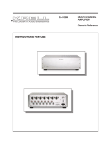
FIGURE 1 FULL POWER BALANCED STEREO AMPLIFIER FRONT PANEL
1 Power Stand-by LED
2 Bias LED
3 Power Button
4 Infrared Sensor
5 Krell CAST LED
6 Regulator LED
1 2 63 54
6 Krell Full Powered Balanced X Series Power Amplifiers

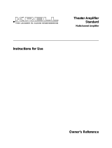
FIGURE 2 FULL POWER BALANCED MONAURAL AMPLIFIER FRONT PANEL
7 Power Stand-by LED
8 Bias LED
9 Power Button
10 Infrared Sensor
11 Krell CAST LED
12 Regulator LED
7 8 129 1110
Krell Full Powered Balanced X Series Power Amplifiers 7

8 Krell Full Power Balanced X Series Power Amplifiers
The front panel accesses power on/stand-by
and infrared sensor (remote control) functions.
The power stand-by, bias, regulator, and Krell
CAST LEDs, arranged in a triangle on the front
panel above the power button, illuminate to indi-
cate amplifier status.
FULL POWER BALANCED
700cx, 400cx, AND 300cx
STEREO POWER AMPLIFIERS
See Figure 1 on page 6
1 Power Stand-by LED
The blue power stand-by LED (top of LED tri-
angle) illuminates when the back panel power
breaker switch has been moved to on, engag-
ing the input circuitry and placing the amplifier
in stand-by mode.
2 Bias LED
The blue bias LED (lower left of triangle) illumi-
nates after the front panel power button is
pressed, indicating that the Sustained Plateau
Bias III is engaged.
3 Power Button
Use the silver power button to power on the
amplifier from stand-by mode.
4 Infrared Sensor
The infrared sensor receives the signal from a
remote control.
5 Krell CAST LED
The red Krell CAST LED (center of triangle) illu-
minates when a Krell CAST input on the back
panel is connected to another Krell product with
a Krell CAST output.
6 Regulator LED
The blue regulator LED (lower right of triangle)
illuminates after the front panel power button is
used to power on from stand-by mode, indicat-
ing that the regulator is providing power to the
output stage.
Note
An optional remote control is available for Full
Power Balanced amplifiers.
FULL POWER BALANCED
750Mcx, 450Mcx, AND 350Mcx
MONAURAL POWER AMPLIFIERS
See Figure 2 on page 7
7 Power Stand-by LED
The blue power stand-by LED (top of LED tri-
angle) illuminates when the back panel power
breaker switch has been moved to on, engag-
ing the input circuitry and placing the amplifier
in stand-by mode.
8 Bias LED
The blue bias LED (lower left of triangle) illumi-
nates after the front panel power button is
pressed, indicating that the Sustained Plateau
Bias III is engaged.
9 Power Button
Use the silver power button to power on the
amplifier from stand-by mode.
10 Infrared Sensor
The infrared sensor receives the signal from a
remote control.
11 Krell CAST LED
The red Krell CAST LED (center of triangle) illu-
minates when a Krell CAST input on the back
panel is connected to another Krell product with
a Krell CAST output.
12 Regulator LED
The blue regulator LED (lower right of triangle)
illuminates after the front panel power button is
used to power on from stand-by mode, indicat-
ing that the regulator is providing power to the
output stage.
Front Panel Description

FIGURE 3 FULL POWER BALANCED STEREO AMPLIFIER BACK PANEL
13 Left and Right Speaker Binding Posts
14 Krell CAST Inputs
15 Back Panel Power Breaker Switch
16 Left and Right Balanced Inputs
17 Krell Link Out/In
18 AC Mains Power Cord
19 Handles
13 1716 161519 191814 14 13
Krell Full Powered Balanced X Series Power Amplifiers 9

FIGURE 4 FULL POWER BALANCED MONAURAL AMPLIFIER BACK PANEL
20 Handle
21 Speaker Binding Posts
22 Krell CAST Input
23 Balanced Input
24 AC Mains Power Cord
25 Krell Link Out/In
26 Back Panel Power
Breaker Switch
21 2523 2420 2622
10 Krell Full Powered Balanced X Series Power Amplifiers

Krell Full Power Balanced X Series Power Amplifiers 11
The back panel provides connections for all
inputs and outputs, power on/off, and remote
control links. The back panel also has handles
that allow you to safely and easily move the
amplifier.
FULL POWER BALANCED
700cx, 400cx, AND 300cx
STEREO POWER AMPLIFIERS
See Figure 1 on page 6
13 Left and Right Speaker Binding Posts
Full Power Balanced 700cx, 400cx, and 300cx
stereo amplifiers are equipped with four pairs of
speaker binding posts (upper left, lower left,
upper right, and lower right).
Notes
Two pairs of speaker binding posts are used for
each channel of amplification. On the stereo or
monaural Full Power Balanced amplifiers,
either the upper or the lower pair can be used
with speakers having two pairs of binding posts.
For biwiring applications, with speakers having
more than one pair of binding posts, use both
upper and lower pairs of speaker binding posts.
See the speaker’s instruction manual for
biwiring connections.
Speaker binding posts for stereo and monaural
amplifiers accept spade lugs only. Bare wire,
banana lugs, or pins will not work. Use the red
terminal for the positive connection and the
blue terminal for the negative connection.
14 Krell CAST Inputs
Full Power Balanced 700cx, 400cx, and 300cx
stereo amplifiers are equipped with one left Krell
CAST input and one right Krell CAST input via 4-
pin bayonet connectors. The Krell CAST inputs
allow the Full Power Balanced amplifier to be
connected to the KPS 25sc Krell Playback Sys-
tem and other CAST-equipped components.
15 Back Panel Power Breaker Switch
Full Power Balanced amplifiers are equipped
with a back panel power breaker switch, for
powering on the amplifier. Placing the back
panel power breaker switch in the up position
places the amplifier in stand-by mode, where it
remains until the front panel power button (3) is
pressed.
Note
Krell recommends that the amplifier remain on,
in stand-by mode, even when not in use, once
it is powered on from the back panel power
breaker switch (15).
16 Left and Right Balanced Inputs
Full Power Balanced 700cx, 400cx, and 300cx
stereo amplifiers are equipped with one left bal-
anced input and one right balanced input via
XLR connectors.
17 Krell Link Out/In
Full Power Balanced amplifiers are equipped
with Krell Link Remote out/in connectors that
allow the remote control to operate a linked
amplifier configuration. See Krell Link Connec-
tions, on page 13 for more information.
Note
An optional remote control is available for Full
Power Balanced amplifiers.
18 AC Mains Power Cord
All Full Power Balanced amplifiers are equipped
with a permanently attached AC power cord.
19 Handles
All Full Power Balanced stereo amplifiers are
equipped with two handles, located beside the
speaker binding posts, to help you easily and
safely move the amplifier.
Back Panel Description

12 Krell Full Power Balanced X Series Power Amplifiers
FULL POWER BALANCED 750Mcx,
450Mcx, AND 350Mcx MONAURAL
POWER AMPLIFIERS
See Figure 4 on page 10
20 Handle
All Full Power Balanced monaural amplifiers are
equipped with a handle, located beside the
speaker binding posts, to help you easily and
safely move the amplifier.
21 Speaker Binding Posts
Full Power Balanced 750Mcx, 450Mcx, and
350Mcx monaural amplifiers are equipped with
two pairs of speaker binding posts (one upper
pair and one lower pair). For stereo operation,
two monaural amplifiers are required.
22 Krell CAST Input
Full Power Balanced 750Mcx, 450Mcx, and
350Mcx monaural amplifiers are equipped with
one Krell CAST input via a 4-pin bayonet con-
nector. The Krell CAST input allows the Full
Power Balanced amplifier to be connected to
the KPS 25sc Krell Playback System and other
CAST-equipped components.
23 Balanced Input
Full Power Balanced 750Mcx, 450Mcx, and
350Mcx monaural amplifiers are equipped with
one balanced input via an XLR connector.
24 AC Mains Power Cord
All Full Power Balanced amplifiers are equipped
with a permanently attached AC power cord.
25 Krell Link Out/In
Full Power Balanced amplifiers are equipped
with Krell Link Remote out/in connectors that
allow the remote control to operate a linked
amplifier configuration. See Krell Link Connec-
tions, on page 13 for more information.
Note
An optional remote control is available for Full
Power Balanced amplifiers.
26 Back Panel Power Breaker Switch
Full Power Balanced amplifiers are equipped
with a back panel power breaker switch, for
powering on the amplifier. Powering on using
the back panel power breaker switch places the
amplifier in stand-by mode, where it remains
until the front panel power button is pressed.
Note
Krell recommends that, once the amplifier is
powered on from the back panel power breaker
switch, it remains on, in stand-by mode, even
when not in use.
Back Panel Description, continued

Krell Full Power Balanced X Series Power Amplifiers 13
INPUT AND OUTPUT
CONNECTIONS
Krell recommends using its proprietary Krell
CAST system for unparalleled sonic perfor-
mance between the Full Power Balanced
amplifiers and other CAST-equipped compo-
nents and the KPS 25sc Krell Playback Sys-
tem.
Full Power Balanced amplifiers also offer bal-
anced operation. The circuitry and connections
associated with balanced operation not only
can minimize sonic loss but also are immune to
induced noise, especially for installations using
long cables.
A one piece RCA-to-XLR adapter is available
from Krell Industries, to allow single-ended oper-
ation using the balanced XLR inputs.
The following steps describe how to connect
cables to the Full Power Balanced Amplifiers.
1. Neatly arrange and organize wiring to and
from the amplifier and all components. Sep-
arate AC wires from audio cables to prevent
hum or other unwanted noise from being
introduced into the system.
2. Connect the Krell CAST cables from your
CAST-enabled preamplifier/source compo-
nent to the left and right Krell CAST 4-pin
bayonet inputs on the amplifier back panel.
For balanced operation, connect the inter-
connect cable from your preamplifier to the
left and right balanced XLR input on the
amplifier back panel.
3. Connect the speaker cables to the Full
Power Balanced amplifier’s speaker binding
posts, located on the amplifier back panel.
Speaker binding posts for both stereo and
monaural amplifiers accept spade lugs only.
4. Insert the end of the AC mains power cord
into the AC wall receptacle.
5. Proceed with Krell Link Connections, if
desired, or turn to Amplifier Operation, on
page 15.
KRELL LINK CONNECTIONS
Krell Link Remote out/in connectors on the
back panel of the Full Power Balanced amplifi-
er allow you to synchronize remote control
operation for systems that include multiple
amplifiers and associated components. When
the Krell Link Remote out/in connectors are
used, the remote capabilities of the linked com-
ponents are controlled from one amplifier or
preamplifier, called the control component. The
linked components respond to stand-by and
operational mode commands from the control
component via MIDI cables.
Note
Krell Link uses standard five pin MIDI commu-
nication cables, sometimes referred to as MIDI
Plus cables. MIDI cables can be purchased
from your authorized distributor or dealer, or
from an audio supply store.
How to Connect Components
through Krell Link
1. Turn all components off, using the back
panel power breaker switch. This ensures
that the components are synchronized when
the MIDI cable is connected.
2. Select the component to be the control com-
ponent. The control component must be in
plain view for proper remote control opera-
tion.
3. Connect one end of the MIDI cable to the
Krell Link out connector on the back panel of
the component.
Connecting the Full Power Balanced
Amplifier to Your System

14 Krell Full Power Balanced X Series Power Amplifiers
4. Connect the other end of the MIDI cable to
the Krell Link in connector on the next com-
ponent.
To link another component, connect a sec-
ond MIDI cable to the Krell Link out con-
nector on the back panel of the second
component. Connect the remaining end of
the MIDI cable to the Krell Link in connec-
tor on the back panel of a third component.
5. Link additional components, if desired, as
described in Steps 3 and 4.
The components are now ready for operation with
Krell Link.
DC PROTECTION CIRCUITRY
Full Power Balanced amplifiers use unobtrusive
direct current (DC) protection circuitry that
strips DC from the signal without corrupting
sound reproduction. Full Power Balanced
amplifiers feature direct coupled circuitry from
input to output. This topology eliminates all cou-
pling capacitors from the audio signal path.
Coupling capacitors block damaging DC but
have sonic characteristics that corrupt sound
reproduction.
Note
For more information about DC protection cir-
cuitry features, see Amplifier Troubleshooting,
on page 17.
USING A TUBE PREAMPLIFIER
The high DC output of tube preamplifiers may
exceed the DC protection circuitry of Full
Power Balanced amplifiers. Excessive DC
level in a signal can damage amplifiers, speak-
ers, or both. The coupling capacitors in Full
Power Balanced amplifiers must be engaged
when using a tube preamplifier. An authorized
Krell dealer, distributor, or Krell must activate
these capacitors.
Coupling capacitors must be inserted into the
signal path by your authorized Krell dealer, dis-
tributor, or Krell before you can use your Full
Power Balanced amplifier with a tube preampli-
fier.
IMPORTANT
Please read the Warranty, on page 20, to
understand the warranty limitations of Full
Power Balanced amplifiers when used with
tube preamplifiers.
Connecting, continued

Krell Full Power Balanced X Series Power Amplifiers 15
Full Power Balanced amplifiers are easy to
install and operate. However, it is important to
exercise care during operation, due to the
amplifiers’ enormous power output. Switching
between active sources (such as a CD player,
tape monitor, or VCR) without muting the pre-
amplifier output, or bumping or miscuing a
source can generate large transients at low fre-
quencies. Full Power Balanced amplifiers may
generate enough power with these transients
to damage loudspeakers.
IMPORTANT
Always mute or fully attenuate the preamplifier
level when switching sources.
Do not change input connections to the amplifi-
er when the amplifier is on.
Use care when setting high playback levels.
Because of their tremendous reserves of clean
power, Full Power Balanced amplifiers can safe-
ly drive speakers to higher sound pressure lev-
els than other amplifiers. Always lower the vol-
ume level at the first sign of speaker distress.
ON/OFF AND STAND-BY OPERATION
When powering on any system, turn on ampli-
fiers last. Turn off amplifiers first.
1. Move the back panel power breaker switch
to the up position to engage the input cir-
cuitry and place the amplifier into the stand-
by mode. The front panel blue power stand-
by LED illuminates.
2. Press the silver power button on the amplifi-
er front panel. The blue regulator LED illumi-
nates. Once the regulator provides power to
the output stage, the blue bias LED illumi-
nates. The Sustained Plateau Bias II system
is now engaged. After the protection circuitry
has confirmed that safe operating conditions
exist, the input relays engage. You hear a
click. The amplifier is ready for operation.
If the Krell CAST input is being used, the
Krell CAST red LED illuminates and
remains illuminated at all times during the
stand-by or power on modes.
3. With the preamplifier muted or volume con-
trol completely lowered, select a source.
Increase the volume control to the desired
listening level.
4. When turning off the system, mute or com-
pletely lower the preamplifier volume, or
place the Full Power Balanced amplifier in
the stand-by power mode by pressing the
power button on the front panel. It is now
safe to turn off the rest of the system.
Note
For best performance of Full Power Balanced
amplifiers, leave the back panel power breaker
switch on at all times.
KRELL LINK OPERATION
1. When all components are linked, place
each component in the stand-by mode by
moving the back panel power breaker
switch to the up position. This ensures that
all components will be synchronized when
signals from the control component are sent
to the linked components in the system.
2. When the components are in stand-by,
switch the control component to the opera-
tional mode from the control component’s
front panel or by using the component’s
remote control.
The linked components switch to the oper-
ational mode simultaneously.
A linked component can be switched between
the operational mode and stand-by, individual-
ly, from its front panel. Switching a linked com-
ponent temporarily breaks the chain of linked
components. To re-establish linked operation,
return all components to stand-by.
Amplifier Operation

16 Krell Full Power Balanced X Series Power Amplifiers
Full Power Balanced amplifiers are compatible
with the remote controls included with Krell pre-
amplifiers, the Home Theater Standard 7.1, and
the KPS 25sc Krell Playback System.
Please contact your authorized Krell dealer, dis-
tributor, or Krell to purchase a remote control for
Full Power Balanced amplifiers.
Full Power Balanced amplifiers can be located
in a room or space close to the speakers but out
of sight, and powered on or off remotely from
the listening room, through a control amplifier.
See Krell Link Connections, on page 13.
HOW TO TURN OFF
THE AMPLIFIER LEDs
The amplifier must be in the stand-by mode
with the rear panel power breaker switch on.
While holding the silver power button in, press
the power key on the remote control. After the
amplifier finishes its turn-on sequence, the front
panel blue LEDs turn off. The blue LEDs remain
off throughout normal operation as long as the
amplifier’s rear panel power breaker switch is
not turned off.
HOW TO TURN ON
THE AMPLIFIER LEDs
With the amplifier in the stand-by mode, turn
the rear panel power breaker switch to the off
position. Then turn the rear panel power break-
er switch back to the on position. The next time
the amplifier is powered up from the front panel
or the remote control, the blue LEDs illuminate
during the turn-on sequence.
HOW TO SWITCH BETWEEN
KRELL CAST AND XLR INPUTS
Press the meter key on a Krell remote to switch
between CAST inputs and the balanced XLR
inputs.
Full Power Balanced amplifiers default to CAST
operation upon startup, if the amplifier is turned
off from the rear panel power breaker switch and
a CAST source and cable are connected to the
CAST inputs. The operational mode does not
change if the Full Power Balanced amplifier is in
stand-by mode.
USING A DEDICATED WALL
OUTLET AND SWITCH
Full Power Balanced amplifiers can be powered
on from an AC wall receptacle with a dedicated
switch, rather than from the front panel power
button or optional remote control.
Please contact your authorized Krell dealer, dis-
tributor, or Krell for more information before you
connect your Full Power Balanced amplifier to a
dedicated AC wall outlet with a switch.
Remote Control
Operation
/