Warnock Hersey northfire dvr36h Installation And Operating Instructions Manual
- Category
- Fireplaces
- Type
- Installation And Operating Instructions Manual
This manual is also suitable for

MODEL NORTHFIRE
DV36-E (Top Vent)
DIRECT VENTED BUILT-IN
GAS FIREPLACE
FOR USE WITH NATURAL GAS AND PROPANE
INSTALLATION AND OPERATING INSTRUCTIONS
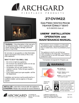
FOR YOUR SAFETY
DO NOT store or use gasoline or any other flammable vapors or liquids in the vicinity
of this or any other appliance
IF YOU SMELL GAS:
- Do not try to light any appliance.
- Open windows.
- Do not touch electrical switches.
- Extinguish any open flame.
- Immediately call your gas supplier from a neighbor's phone. Follow the gas supplier’s
instructions.
- If you cannot reach the gas supplier, call the fire department.
PLEASE READ INSTRUCTIONS CAREFULLY BEFORE INSTALLING AND
OPERATING THE APPLIANCE
WARNING:
Improper installation, adjustment, alteration, service or maintenance voids
all the manufacturer’s warranties and may cause property damage, personal injury or
loss of life.
Installation and service must be performed by a qualified installer, service agency or the
gas supplier.
Installer, please leave this manual with the appliance owner for future reference.
WARNOCK HERSEY
CERTIFIED FOR CANADA AND USA
NOT FOR USE WITH SOLID FUEL
200-0055 22JAN02
f i r e - p a r t s . c o m

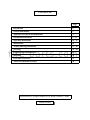
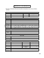
CONTENTS
Introduction 2
General Information 3
Appliance Description and Dimensions 4
Installation Instructions 5 - 13
Operation Instructions 14 - 15
Maintenance 16
Trouble Shooting Instructions 17 - 18
Servicing 19 - 20
Important Information Form 21
Warranty 22
Parts and Accessories 23
Allowed Termination Location 24
Page
Manufactured by Archgard Industries Ltd, British Columbia, Canada.
Patents Pending
f i r e - p a r t s . c o m

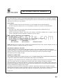
INTRODUCTION
Thank you for purchasing the NorthFire-DVT36E Direct Vent Built-in Gas Fireplace.
The NorthFire-DV36E is one of the most advanced gas fireplaces on the market. It is designed
using the latest technology and manufactured to the highest quality.
Some of the many features are:
∗ Small Size The NorthFire-DV36E is compact enough to fit into almost any size
room.
.
∗
Solid Construction The NorthFire-DV36E is constructed mainly of satin coated and
galvanized steel for long life and durability.
Please read the manual carefully prior to installation and operation of the appliance.
Proper installation, operation and maintenance of the appliance will provide you with
many years of enjoyment.
CAUTION
Due to high temperatures, the appliance should be located out of traffic and away from
furniture and draperies.
Children and adults should be alerted to the hazards of high surface temperature and
stay away to avoid burns or clothing ignition.
Young children should be carefully supervised when they are in the same room as the
appliance.
Clothing or other flammable material should not be placed on or near the appliance.
Any parts removed or opened for servicing of the appliance must be properly replaced
prior to operating the appliance.
The appliance must be inspected before use and at least annually by a qualified service
person. More frequent cleaning maybe required due to excessive lint from carpeting,
bedding material, etc. It is imperative that the control compartments, burners and
circulating air passageways for the appliance be kept clean.
2
f i r e - p a r t s . c o m

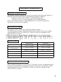
GENERAL INFORMATION
This appliance is listed by Warnock Hersey for use in both the United States and Canada. It is
tested and certified to the following US and Canadian gas appliance standards.
- ANSI Z21.50-1996 / CGA 2.22-M96, Vented Gas Fireplace and
- CAN/CGA-2.17-M91, Gas-Fired Appliances for Use at High Altitudes.
Please contact Warnock Hersey or Archgard Industries Ltd., if you have any questions
regarding the certification of this appliance.
APPLIANCE CERTIFICATION
INSTALLATION CODES
This appliance must be installed by a qualified gas appliance installer.
The installation must conform with the local codes or, in the absence of local codes, with the
current National Fuel Gas Code, ANSI Z223.1/ NFPA 54, in the US or Installation Code,
CAN/CGA-B149, in Canada.
Electrical connections and grounding must conform with local code, or current National
Electrical code, ANSI/NFPA No. 70-1987, in the US and in Canada, the current Canadian
Electrical Code, CSA C22.1.
HIGH ALTITUDE INSTALLATION
When installing this appliance beyond 4500 ft. (1372 m) above sea level. The appliance must be
properly de-rated and installed according to local codes, in the absence of local codes, with the
current National Fuel Gas Code, ANSI Z223.1/ NFPA 54, in the US or Installation Code,
CAN/CGA-B149, in Canada.
3
Natural Gas (NG) Propane (LP)
Manifold Pressure
3.5 in. w.c. ( 0.9 kPa) 10.0 in. w.c. ( 2.5 kPa)
Min. Supply Pressure for Purpose
of Input Adjustment
4.5 in. w.c. (1.2 kPa) 11.0 in. w.c. (2.8 kPa)
Orifice Size
#48 DMS ( 1.93 mm dia.) #56 DMS ( 1.18 mm dia.)
Nominal Input Rating
16,000 BTU/hr (5.8 kW) 16,000 BTU/hr ( 5.8 kW)
Altitude
0 - 4,500 ft. (0 - 1372 m) 0 - 4,500 ft. (0 - 1372 m)
Primary Air Opening
1/4 in. (6.4 mm) 1/2 in. (12.7 mm)
SPECIFICATIONS
f i r e - p a r t s . c o m

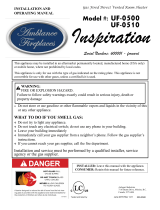
APPLIANCE DESCRIPTION & DIMENSIONS
4
GAS VALVE
CONVECTION FAN
SPEED CONTROL
TOP LOUVERS
GLASS DOOR
APPLIANCE DIMENSIONS
FRONT VIEW
36 1/4”
23 1/2”
37 3/4”
TOP VIEW
SIDE VIEW
FRONT VIEW
3 1/2”
* Except for the vent connector locations, the rear vented DVR36H and top vented DVT36H, have
the same physical dimensions.
5 1/4”
3/4”
f i r e - p a r t s . c o m

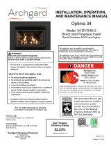
B
C
F
D
E
A
A Cross Corner
B Flush with Wall
C Flat on Wall Corner
D Flat on Wall
E
Island
F
Room Divider
15 ft Max.
15 ft Max.
INSTALLATION INSTRUCTIONS
PRECAUTIONS
•
This appliance must be installed by a qualified gas installer and the installation conform to the
installation codes.
•
Provide adequate clearance around air openings of the appliance. Never obstruct front openings.
•
Provide adequate clearances for proper operation and servicing of the appliance.
•
This appliance must be properly connected to a venting system.
5
LOCATING GAS FIREPLACE
This appliance must be installed in any location that is free of plumbing, electrical wiring and heating or
air conditioning ducts. Select a location that is accessible for venting. See APPENDIX A.
ALLOWABLE TERMINATION LOCATIONS.
VENT TERMINATION
1. See “ALLOWABLE TERMINATION LOCATIONS” diagram (page 24) to establish a suitable vent
termination location.
2. In heavy snowfall areas make sure vent termination is located where it can not be blocked by snow or
snow from snow removal equipment.
3. Locate vent termination away from plants, bushes or any other object on or near the vent termination
that will interfere or obstruct the air flow around it.
4. DO NOT recess vent termination into walls, sidings or planters.
5. Vent terminations located below 7ft from grade level or anywhere it can be a burn hazard to the public,
such as patios and balconies, must be protected with an Archgard approved termination cage.
6. Always ensure bottom of Vent Terminal is a minimum of 12” above grade.
*NOTE: Rear vented gas fireplace DVR36H can only be located in positions
A, B, C and D.
f i r e - p a r t s . c o m

INSTALLATION INSTRUCTIONS
Cont...
6
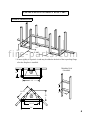
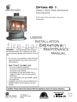
FRAMING DIMENSIONS
36 1/4”
16”
39 1/2”
28”
36 1/4”
56”
36 1/4”
*31”
16”
* If more rigidity is required. A stud may be added to the back of the top nailing flange
after the fireplace is installed.
TERMINATION
FRAMING
11”
10”
f i r e - p a r t s . c o m

INSTALLATION INSTRUCTIONS
Cont...
VENTING
The appliance will not function without being connected to a proper venting system.
This appliance may use 4” and 7” gas flex vents with NorthFire-DV36H listed vent components, or Simpson
Duravent 4 x 6 5/8 direct vent systems with Simpson Duravent Adaptor (SDA-1). 7” dia. rigid vent may
directly replace 7” dia. flex vent in all applications.
For best venting performance using gas flex vent, here are some general venting rules that we recommend:
1. Use only 4”and 7” diameter 2-ply certified gas flex vent in a co-axial configuration.
2. Maintain a minimum clearance of 1” to the sides and bottom and 2” to the top outside surface of the vent
pipe and combustible material.
3. Observe any local code restrictions, if any, regarding the installation of this type of gas appliance.
4. Observe the venting chart given in this manual.
5. Use a vent spacer between the inside and outside flex vents at every 3 ft intervals.
6. Never slope horizontal running vents downwards.
7. Maintain at least an upward slope of 1” for every 1 ft of horizontal run on the rear vented models.
8. Terminate the vent with a vent termination supplied by Archgard Industries Ltd.
9. Support horizontal running vents every 3 ft to prevent it from sagging.
10.Wall terminal must be installed a minimum of 12” above grade measured from bottom of terminal.
CLEARANCES TO COMBUSTIBLES
Combustible mantle allowed in shaded area. Mantle
extension may be increased 1” (25mm) for each
additional 1” (25mm) increase in clearance height.
6” (152 mm)
Minimum Height From Top Surround: 6”
Minimum Height From
Bottom of Appliance: 35”
7
BACK
0” to stand-offs
SIDES
0” to stand-offs
TOP 0” to stand-offs
BOTTOM
0”
ADJACENT SIDE WALL
1” to side of faceplate
MANTLE see diagram
VENT
1” to outside side and bottom surface,
2” to outside top surface.
f i r e - p a r t s . c o m

INSTALLATION INSTRUCTIONS
Cont...
9
INSTALLATION INSTRUCTIONS
Cont...
RESTRICTOR PLACEMENT “FOR ABOVE 7 FOOT VERTICAL RISE VENTED
APPLICATIONS ONLY”
Vertical Venting between Seven Feet (7’) and Ten Feet (10’) requires
Restrictor Number 1 as per the Venting Chart on page 8.
Simpson Duravent Archgard System
Archgard System
In the Archgard system the restrictors are placed on the exhaust outlet on the appliance.
Simpson Duravent
With Simpson Duravent locate the restrictor in the exhaust section fitting into the formed lip.
Restrictor Placement
WARNING:
These restrictors are only to be installed in the vent system if the vent exceeds 7’
in vertical height. *See below which restrictor is required.
Installing them
under any other circumstances may cause hazardous venting conditions
and may result in personal injury, property damage or death.
NOTE:
Vent restrictors are designed to reduce vertical stack action for above 7 feet (7’),
which will reduce the velocity of incoming combustion air and not adversely affect the standing
pilot or the flame of the appliance.
8
Vertical Venting between Ten Feet (10’) and up to a maximum
Twenty-five Feet (25’) requires Restrictor Number 2 as per the
Venting Chart on page 8.
f i r e - p a r t s . c o m

INSTALLATION INSTRUCTIONS
Cont...
9
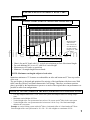
VENTING
Cont...
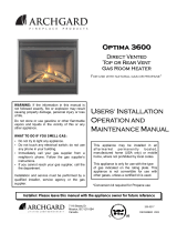
•
Chart is for one 90° bend, with 1/4” vertical raise minimum per foot of horizontal length.
•
For each additional 90° or two 45°, add 1ft of vertical height.
•
Maximum two 90º bends, or equivalent.
•
Minimum 2 ft straight length between bends.
Maintain a minimum of 1” clearance to combustibles on sides and bottom and 2” from top surface
of the vent.
The gas fireplace is designed and optimized for majority of the installations with short vents. With
taller vents the efficiency and flame characteristics will change. Therefore, an exhaust restrictor
plate is provided by the manufacturer to preserve as much of the original short vent performances as
possible on taller vent configurations.
NOTE: Maximum vent lengths subject to local codes.
VENTING CHART (FOR TOP VENTED APPLIANCES ONLY)
10 ft
36”
3 ft 1 ft 15 ft
HORIZONTAL LENGTH
(from center of flue outlet to base of termination)
VERTICAL HEIGHT
(from bottom of appliance to center of termination)
7 ft
Venting in this area requires a vent restrictor plate #1.
5 ft 7 ft 9 ft 11 ft 13 ft
30”
Heater
Maximum Hori-
zontal run for
Rear Vent is 20”
from the back of
the unit to termi-
nation or 16” with
a 45
0
elbow.
VERTICAL VENTING (THROUGH THE ROOF) FOR ROOFTOP VENTED APPLIANCES
•
Use only Simpson Duravent 4 x 6-5/8” direct vent systems and Simpson Duravent venting compo-
nents.
•
Maximum vertical height of 25 feet.
•
Vertical height of the vent system must have at least 3 ft or more per 90
0
elbow in the vent system.
•
Vertical height of the vent system must also be increased 1 ft for every 2 ft of horizontal length
added to the vent system.
Example: A vertical venting system with a 90
0
elbow, a horizontal offset of 4 ft and another 90
0
elbow.
Vertical height of the vent system must be 3ft + 2ft + 3ft = 8ft or higher to a maximum of 25 ft.
Vertical Venting between 10 ft and maximum 25 ft requires restrictor plate #2
f i r e - p a r t s . c o m

GAS CONNECTIONS
Before connecting the appliance to the gas supply line, double check that the appliance you
have purchased is designed for the gas type you are using. The gas type markings are located
on the certification label and also on the appliance’s gas valve.
Provide adequate clearance for proper installation and checking of the gas connections.
Have your gas supplier or a qualified gas fitter run a gas supply line into the gas fireplace. The
line must be properly sized and fitted according to the installation codes. Up stream of the
appliance supply connection, the fitter shall provide an easily accessible manual shut-off valve.
CAUTION:
The appliance and its individual shutoff valve must be disconnected from the
gas supply piping system during any pressure testing of that system at test
pressures in excess of 1/2 psig (3.5 kPa). The appliance must be isolated from
the gas supply piping system by closing its individual manual shutoff valve
during any pressure testing of the gas supply piping system at test pressures
equal to or less than 1/2 psig (3.5 kPa). Failure to do so will damage the
appliance’s gas valve. Such damage is not covered by the manufacturer’s
warranty.
Check for proper gas supply pressure by loosening the set screw on the supply pressure tap
(marked
IN
) on the gas valve with a small flat tip screw driver and placing a test gauge on the
tap.
The minimum permissible gas supply pressure is 4.5 in. w.c. (1.12 kPa) for natural gas and
11.0 in. w.c. (2.74 kPa) for propane. Maximum gas supply pressure should never exceed 14.0
in. w.c. (3.48 kPa) or 1/2 psi. for both natural gas and propane.
BE SURE TO TIGHTEN THE PRESSURE TAP SET SCREW AFTER CHECKING
THE PRESSURE. CHECK ALL GAS CONNECTIONS FOR GAS LEAKS.
INSTALLATION INSTRUCTIONS
Cont...
10
Please follow the venting instructions as strictly as possible to obtain the best
performance from the appliance.
f i r e - p a r t s . c o m

INSTALLATION INSTRUCTIONS
Cont...
GLASS DOOR
11
WARNING: Do not attempt to remove the glass door when the appliance is hot.
Removing the Glass Door
Remove the top and bottom louvers.
There are two latches under the firebox. Undo the latches, swing the bottom of the door away
from the appliance and then lift the door off the top retaining tabs. Carefully place the door in a
safe location where it cannot be scratched or damaged.
Replacing the Glass Door
The reverse procedure of Removing the Glass Door.
Buckle latch
Buckle latch
Top of door hooks
onto fireplace
f i r e - p a r t s . c o m

INSTALLATION INSTRUCTIONS
Cont...
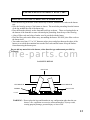
PLACEMENT OF LOGSET, FIBRE COALS & EMBER WOOL
•
Place the back log at the back of the burner tray as shown, behind the two tabs on the burner
tray.
•
Place the front log on top of the burner as shown. The metal tabs protruding from the bottom
of the log straddle the side of the burner top.
•
Place the branches directly on the front and back logs as shown. There are locating holes on
the bottom of the branches to mate with metal pins protruding from the top of the front log.
•
A bag of fibre coals and a bag of ember wool is provided with the heater.
•
Place the fibre coals on the burner tray, surrounding the burner. DO NOT place fibre coals on
the burner itself.
•
Tear ember wool into 1/2” to 3/4” diameter ember pieces and place them on the edges of the
burner so as to hide the transition between the fibre coals and the burner. Keep the embers
from obstructing the burner ports.
Do not add any materials to the burner, other than the type and amount provided by
Archgard.
12
LEFT BRANCH RIGHT BRANCH
BACK LOG
WARNING : Do not place the logs and branches in any configuration other then the one
shown, a fire, explosion or excessive carbon monoxide (CO) may result,
causing property damage, personal injury or loss of life.
LOG SETUP DETAIL
COALS
EMBERS
FRONT LOG
f i r e - p a r t s . c o m

INSTALLATION INSTRUCTIONS
Cont...
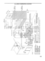
ELECTRICAL CONNECTIONS (for optional convection fan kit FK 36/38 only)
•
Install the fan first. Remove the lower louvers and gently place the bottom front lip of the blower
mounting bracket into the opening. Slide the blower assembly into the bottom of the fireplace. Rotate
the blower into position. Be careful not to damage the fan blades. The fan blades will now face towards
you. Line up the holes on fan bracket to the mounting bracket at the bottom of the fireplace. Place a
screw at each of the three holes and tighten.
•
Run 120VAC power line through the left side of the fireplace and into the bottom of the gas fireplace.
•
Be sure to connect a grounding wire to the side of gas fireplace. Use any screw hole on the side for this
purpose.
•
Slide the thermal snap switch into the fork like bracket underneath the left side of the firebox.
•
Neatly tie down and tuck the wires down at the bottom and to the back of the fireplace.
•
CAUTION: Do not allow any wires to touch the bottom of the firebox. Otherwise, the wires will melt
and short-out.
•
Screw the speed controller bracket to the bottom left sidewall of the gas fireplace.
SPEED CONTROL
LINE
CONVECTION FAN
GROUND
110F (43ºC) N.O.
THERMAL SNAP SWITCH
NEUTRAL
TO
APPLIANCE
120 VAC
WIRING DIAGRAM
13
VALVE CONNECTIONS
PILOT
ASSEMBLY
REMOTE WALL SWITCH
OPTIONAL
THERMOSTAT
THERMOPILE
SPARK ELECTRODE
THERMOCOUPLE
PILOT BURNER
SPARKER
f i r e - p a r t s . c o m

OPERATION INSTRUCTIONS
FOR YOUR SAFETY, READ BEFORE LIGHTING
WARNING :
If you do not follow these instructions exactly, a fire or explosion
may result, causing property damage, personal injury or loss of
life.
This appliance has a pilot which must be lit by hand using the sparker located next
to the appliance valve controls. When lighting the pilot, follow the start-up
procedures exactly.
Do not use this appliance if any part has been under water. Immediately call a
qualified service technician to inspect the appliance and to replace any part of the
control system and any gas control which has been under water.
Use only your hand to push in or turn the gas control knob. Never use tools. If the
knob will not push in or turn by hand, don’t try to repair it. Call a qualified service
technician. Force or attempted repair may result in a fire or explosion.
BEFORE LIGHTING, smell all around the appliance area for gas. Be sure to smell
next to the floor, because some gases are heavier than air and will settle on the
floor. IF YOU SMELL GAS, follow the instruction on the front cover of this
manual.
A.
B.
C.
D.
INITIAL OPERATION
• Check that the appliance is properly vented and connected to the gas supply.
• Check that the logs and branches are properly placed.
• Check all external parts, such as grills, door and control cover are properly attached and
fastened.
• Check to ensure the pressure relief door on top of the firebox and behind the upper
louvres is closed and properly sealed on the gasket.
NOTE :
When operated for the first few times, the appliance will emit some odors and
fumes. This is due to the evaporation of oils and solvents used in fabricating the
appliance. Close off the room to the rest of the house and open all windows. Keep
the room well ventilated. Operate the appliance continuously on high setting for at
least 4 to 6 hours. This will ‘burn-in’ the appliance and reduce the chance of odors
and fumes reoccurring the next time the appliance is used.
14
f i r e - p a r t s . c o m

Sparker
Control Knob
Set the thermostat, if present, to the lowest level. Press slightly and turn the control knob
clockwise
3
to the OFF position and wait 5 minutes; thus allowing any gases to escape
which may have accumulated in the combustion chamber.
Note:
LP gases do not vent upward. Then follow step 2 and 3 to establish pilot.
OPERATION INSTRUCTIONS
Cont..
Press and turn control knob counterclockwise
4
to
ON
position.
Release control knob. If pilot should go out, turn the control knob to OFF position and
repeat steps 1, 2 and 3.
Note:
this will allow reset of INTERLOCK for proper lighting of pilot.
Press slightly and turn control knob counterclockwise
4
to
PILOT
position; depress
control knob and light pilot by repeatedly pressing the sparker. Venting of air may take
place at the pilot prior to the flow of fuel gases. Once flame is established, hold knob
depressed for approximately 60 sec.
START-UP PROCEDURE
1.
2.
3.
4.
5.
6.
Turn thermostat to the desired comfort level or turn ON/OFF switch to the ON position.
7.
TEMPORARY SHUT-DOWN PROCEDURE
To turn off the main burner only, set the thermostat to the lowest setting or turn remote
switch to OFF. Press and turn the control knob clockwise
3
to PILOT position.
Press and turn the control knob clockwise
3
to the
OFF
position.
COMPLETE SHUT-DOWN PROCEDURE
15
f i r e - p a r t s . c o m

MAINTENANCE
CAUTION :
Only conduct maintenance on a cold appliance.
The exterior painted surfaces, glass and gold trims may be cleaned with a soft, non-abrasive
cloth and water or a suitable, mild, non-abrasive cleaner.
Regularly,
•
Clean and remove any lint accumulations or debris from the grills and in any
combustion and convection air passage ways.
•
Keep the appliance area free from combustible materials, such as paper, wood,
clothing, gasoline and flammable solids, liquids and vapors.
•
Visually check the height and color of the burner and pilot flames.
•
Check for unusual noise, odor and operation of the appliance.
•
Check the vent terminal for any damage, or obstruction by plants or debris
accumulation.
Once a Year,
•
Remove the glass door and clean the inside of the glass with a soft, non-abrasive
cloth and water or a suitable, mild, non-abrasive cleaner.
•
Carefully remove the logs and gently brush off any loose carbon deposits. This job is
best done outside the house, wearing a dust mask.The logs are very fragile, take care
not to break them. After cleaning, the logs must be replaced as per the instructions in
this manual.
•
When replacing glass door, ensure the gasket is still secure all around the edge of the glass
and it is sealing against the firebox frame. Replace the gasket is worn, damaged or falling off.
Once a Year have a qualified service technician,
•
Completely inspect the appliance and the venting system.
•
Clean and remove any lint accumulations or debris in the firebox, on the burners, on
the pilot, at the primary air opening, on the optional convection air blower and in any
combustion and convection air passage ways.
•
Check the safety system of the gas valve.
•
Check condition of both glass door gasket and top pressure relief door gasket.
Replace if damaged or worn.
WARNING :
All parts removed or disturbed must be properly replaced after maintenance.
Service and repair must be conducted by a qualified service person. If these
instructions are not followed, a fire or explosion may result, causing property
damage, personal injury or loss of life
CLEANING THE APPLIANCE
16
f i r e - p a r t s . c o m

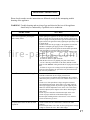
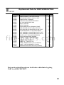
TROUBLE SHOOTING
SYMPTOM ACTION
Pilot will not light after pressing the
sparker many times.
1. When lighting the appliance for the first time after installation or
after servicing, there is air in the gas line. It takes a while for all
the air to purge out of the pilot before gas can reach the pilot and
ignite. Remove the glass door and try lighting the pilot many times
to purge the air.
2. Check to make sure the gas supply to the appliance is turned on
and there is adequate gas supply pressure to the appliance.
3.Check for sparks between the spark electrode and the pilot head
when the sparker is pressed. If there are no sparks,
a. Check for broken or poor connection from the sparker to the
electrode.
b. Check for the spark shorting or arcing at other locations.
c. Check for defective sparker.
d. Check for defective spark electrode.
4. With the door removed, try lighting the pilot with a match.
a. If air is blowing on the flame of the match, hold the control
knob in at the ‘
PILOT
’ setting until all the air is purged out of the
line.
b. If there is no gas or air coming out of the pilot and there is gas
pressure to the appliance, the pilot orifice may be blocked or the
gas valve may be defective.
Pilot will not remain on after being lit.
1. Press the control knob all the way in.
2. Hold the control knob in for a longer period of time.
3. If you are trying to re-light the pilot immediately after you have
shut-off the pilot, you have to wait a few minutes for the valve to
reset.
4. Check to see if the pilot flame is large enough to reach and
surround the thermocouple. If the flame is too small, check for
correct gas supply pressure. If pressure is good, adjust the pilot
flame size with the adjustment screw on the valve. If the flame
cannot be adjusted, there might be some debris obstructing the
pilot orifice.
5. Check for poor connection of the thermocouple to the valve.
6. Check for proper millivolts of the thermocouple. The
thermocouple should generate at least 30 mV or it is defective.
7. Check for defective gas valve.
The main burner does not turn on with
the pilot lit.
1. Check to make sure the control knob is turned to the ‘ON’
position.
2. The thermopile takes a bit of time to heat up and generate enough
voltage to activate the valve. Wait a little longer.
Please check to make sure the instructions are followed exactly before attempting trouble
shooting of the appliance.
WARNING:
Trouble shooting and servicing of gas and electrical devices of the appliance
should only be conducted by a qualified service technician.
17
f i r e - p a r t s . c o m

18
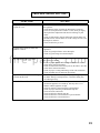
TROUBLE SHOOTING
Cont...
SYMPTOM ACTION
The main burner does not turn on with
the pilot lit.
Cont...
3. Check to make sure the thermostat is set high enough to turn on
the appliance.
4. Check that the remote switch or the thermostat is turned on.
5. Check for weak pilot flame. If flame is weak, check gas supply,
check pilot flame adjustment and check for blockage of pilot
orifice.
6. Check for 400-500 mV from the thermopile with the burner off
and 200-250 mV with the burner on. If the voltages are lower, the
thermopile is defective.
7. Check for defective gas valve.
The main burner shuts off when the
appliance is warm.
1. This may be the normal operation of a wall thermostat installed to
appliances.
2. Check for good pilot flames on the thermopile.
3. Check for good voltage from the thermopile.
Sooty deposits on the glass door.
1. If the flame is yellow and lazy, increase primary air by opening
the primary air shutter.
2. Check for proper placement of the logs and branches. See that
section in the instruction manual.
3. Check for obstruction of the burner ports by the embers. See that
section in the instruction manual.
4. Check for proper venting and blockage of the vent termination.
5. Check manifold pressure and clock input rating.
Sharp blue flames with flames lifting off
the burner at the ends.
1. Too much primary air. Reduce primary air by closing the primary
air shutter. During cold temperatures, some flame lifting may
occur during start-up.
Convection blower does not turn on.
1. The convection fan is thermostatically controlled. It will only turn
on when the appliance is warmed-up. This may take 5 to 15
minutes with the appliance on high.
2. Check for 120VAC electrical supply to the appliance.
3. Check for proper mounting of the thermal snap disc.
4. Check electrical connections.
5. Check for defective thermal snap disc.
6. Check for defective convection blower speed controller.
7. Check for defective convection blower.
f i r e - p a r t s . c o m

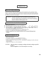
SERVICING
Before servicing, read the terms and conditions of the Archgard warranty at the back of the
manual. Contact the Archgard authorized dealer from which you have purchased the appliance
and provide him with details of the problem and the installation information which the installer
has filled out at the back of the manual.
WARNING:
Servicing of this appliance must be conducted by a qualified service
technician. Improper servicing, adjustment or alteration of this appliance
may cause property damage, personal injury or loss of life. All servicing
should be conducted with the appliance cold.
•
Remove the glass door.
•
The primary air shutter is located underneath the burner.
•
Loosen the air shutter screw with a Philips (‘+’) screwdriver.
•
Rotate air shutter with a flat tip screw driver. The primary air opening size can be easily seen
with a flashlight.
•
Tighten the air shutter screw after adjustment.
CAUTION: Adjust the primary air opening according to the shutter settings as specified
on page 3.
Ensure the appliance is cool to the touch prior to servicing.
ADJUSTING PRIMARY AIR
SERVICING UNDER WARRANTY
19
•
Remove the bottom grill.
•
The pressure test taps are located on front of the valve.
•
The supply pressure is marked ‘
IN
’ and the manifold pressure is marked ‘
OUT
’. There is
also an arrow marking the direction of gas flow.
•
Loosen the screw inside the tap with a 1/8” wide flat screw driver.
•
Connect a 1/4” rubber tube to the tap and a pressure gauge.
•
Be sure to tighten the screw inside the tap after you are finished taking pressure
readings.
CHECKING INLET AND OUTLET GAS PRESSURE
f i r e - p a r t s . c o m
Page is loading ...
Page is loading ...
Page is loading ...
Page is loading ...
Page is loading ...
Page is loading ...
-
 1
1
-
 2
2
-
 3
3
-
 4
4
-
 5
5
-
 6
6
-
 7
7
-
 8
8
-
 9
9
-
 10
10
-
 11
11
-
 12
12
-
 13
13
-
 14
14
-
 15
15
-
 16
16
-
 17
17
-
 18
18
-
 19
19
-
 20
20
-
 21
21
-
 22
22
-
 23
23
-
 24
24
-
 25
25
-
 26
26


Warnock Hersey northfire dvr36h Installation And Operating Instructions Manual
- Category
- Fireplaces
- Type
- Installation And Operating Instructions Manual
- This manual is also suitable for
Ask a question and I''ll find the answer in the document
Finding information in a document is now easier with AI
Other documents
-
FMI MP6-WI Operating instructions
-
 Archgard Optima 72 Maintenance Manual
-
Enviro C-11275 User manual
-
Archgard Optima 45 - 3 Specification
-
-
 Archgard 27-DVIM22 Specification
-
 Archgard Optima 45-1 Users Installation Operation & Maintenance Manual
-
 Ambiance Fireplaces Inspiration UF-0510 Installation guide
-
 Archgard Optima 34 User manual
-
 Optima Company Optima 3600 User manual


