Page is loading ...

Combitherm®
Combination
Oven / Steamer
ES GAS
COMBITOUCH™
SERIES
6•10ESG
10•10ESG
7•14ESG
10•20ESG
12•18ESG
20•20ESG
• INSTALLATION
W164 N9221 Water Street • P.O. Box 450 • Menomonee Falls, Wisconsin 53052-0450 USA
PHONE: 262.251.3800 • 800.558.8744 USA/CANADA FAX: 262.251.7067 • 800.329.8744 U.S.A. ONLY
WWW.ALTO-SHAAM.COM
PRINTED IN U.S.A.
MN-29246 • 10/10

i
Delivery .......................................................................... 1
Unpacking ..................................................................... 1
Safety Procedures and Precautions .............................. 2
Installation
Installation Codes and Standards ............................. 3
Ventilation Requirements ........................................... 3
Positioning on Site .................................................... 4
Positioning Requirements ......................................... 5
Stand Installation ...................................................... 5
Common Specications ............................................ 6
Specications, 6•10esG ............................................ 7
Specications, 10•10esG .......................................... 8
Specications, 7•14esG ........................................... 9
Specications, 10•20esG ........................................ 10
Specications, 12•18esG ........................................ 11
Specications, 20•20esG ........................................ 12
Electrical Connection ............................................... 13
Mobile Equipment Restraint ..................................... 14
Ventilation Requirements ......................................... 15
Gas Supply & Installation ......................................... 16
Gas Leak Testing ...................................................... 19
Gas Exhaust ............................................................. 19
Water Quality Requirements .................................... 20
Water Supply & Installation ...................................... 21
Water Valve .............................................................. 22
Water Drainage......................................................... 22
CombiTouch Checklist ............................................ 23
Error Codes ............................................................. 24
Warranty
Original Equipment Limited Warranty ...................... 30
Transportation Damage and Claims ......................... 31

COMBITOUCH
TM
ESG SERIES • GAS INSTALLATION MANUAL • 1.
THE INFORMATION CONTAINED IN THIS
MANUAL IS IMPORTANT FOR THE PROPER
INSTALLATION OF THIS OVEN. PLEASE READ
CAREFULLY AND RETAIN FOR
FUTURE REFERENCE.
IMPROPER CONNECTION OF THIS APPLIANCE
WILL NULLIFY ALL WARRANTIES.
LES INFORMATIONS CONTENUES DANS CE
MANUEL SONT IMPORTANTES POUR UNE
INSTALLATION CORRECTE DE CE FOUR.
PRIÈRE DE LE LIRE ATTENTIVEMENT ET DE
LE CONSERVER POUR POUVOIR S’Y RÉFÉRER
À L’AVENIR.
UN BRANCHEMENT INCORRECT DE
CET APPAREIL ANNULERA TOUTES LES
GARANTIES.
DELIVERY
This Alto-Shaam appliance has been
thoroughly tested and inspected to ensure only
the highest quality unit is provided. Upon
receipt, check for any possible shipping damage
and report it at once to the delivering carrier.
See Transportation Damage and Claims section
located in this manual.
This appliance, complete with unattached
items and accessories, may have been delivered
in one or more packages. Check to ensure that all
standard items and options have been received
with each model as ordered.
Save all the information and instructions
packed with the appliance. Complete and return
the warranty card to the factory as soon as
possible to ensure prompt service in the event of a
warranty parts and labor claim.
This manual must be read and understood
by all people using or installing the equipment
model. Contact the Alto-Shaam Tech Team Service
Department if you have any questions concerning
installation, operation, or maintenance.
NOTE: All claims for warranty must include the
full model number and serial number of
the unit.
UNPACKING
1. Carefully remove the
appliance from the
carton or crate.
NOTE: Do not discard the
carton and other
packaging material
until you have
inspected the unit
for hidden damage
and tested it for
proper operation.
2. Read all instructions in this manual carefully
before initiating the installation of this appliance.
DO NOT DISCARD THIS MANUAL.
This manual is considered to be part of the
appliance and is to be provided to the owner
or manager of the business or to the person
responsible for training operators. Additional
manuals are available from the Alto-Shaam
Tech Team Service Department.
3. Remove all protective plastic film, packaging
materials, and accessories from the appliance
before connecting electrical power. Store any
accessories in a convenient place for future use.
®
®
CAUTION
TO PREVENT PERSONAL INJURY,
USE CAUTION WHEN MOVING OR
LEVELING THIS APPLIANCE.

COMBITOUCH
TM
ESG SERIES • GAS INSTALLATION MANUAL • 2.
CAUTION
Used to indicate the presence of a hazard that
can or will cause minor personal injury, property
damage, or a potential unsafe practice if the
warning included with this symbol is ignored.
CAUTION
Used to indicate the presence of a
hazard that can or will cause minor or
moderate personal injury or property
damage if the warning included with
this symbol is ignored.
DANGER
Used to indicate the presence of
a hazard that WILL cause severe
personal injury, death, or substantial
property damage if the warning
included with this symbol is ignored.
WARNING
Used to indicate the presence of
a hazard that CAN cause personal
injury, possible death, or major
property damage if the warning
included with this symbol is ignored.
1. This appliance is intended to cook, hold
or process foods for the purpose of human
consumption. No other use for this appliance is
authorized or recommended.
2. This appliance is intended for use in commercial
establishments where all operators are
familiar with the purpose, limitations, and
associated hazards of this appliance. Operating
instructions and warnings must be read and
understood by all operators and users.
3. Any troubleshooting guides, component views,
and parts lists included in this manual are for
general reference only and are intended for use
by qualified technical personnel.
4. This manual should be considered a permanent
part of this appliance. This manual and all
supplied instructions, diagrams, schematics,
parts lists, notices, and labels must remain with
the appliance if the item is sold or moved to
another location.
NOTE: Used to notify personnel of
installation, operation, or
maintenance information that is
important but not hazard related.
SAFETY PROCEDURES
AND PRECAUTIONS
Knowledge of proper procedures is essential to the
safe operation of electrically and/or gas energized
equipment. In accordance with generally accepted
product safety labeling guidelines for potential
hazards, the following signal words and symbols
may be used throughout this manual.
CAUTION
WHEN WELDING ANY STAINLESS
STEEL COMPONENTS ON THIS
APPLIANCE, THE ELECTRONIC
CONTROL BOARDS MUST BE
ISOLATED FROM THE APPLIANCE.
NOTE
For equipment delivered for use
in any location regulated by the
following directive:
DO NOT DISPOSE OF ELECTRICAL
OR ELECTRONIC EQUIPMENT WITH
OTHER MUNICIPAL WASTE.

COMBITOUCH
TM
ESG SERIES • GAS INSTALLATION MANUAL • 3.
INSTALLATION
SITE INSTALLATION
INSTALLATION CODES & STANDARDS
The following codes and standards are required for
installation of this oven:
AIR SUPPLY, ELECTRICAL CONNECTIONS,
WATER CONNECTIONS, AND WASTE WATER
DISCHARGE.
Installation must comply with local codes required
for gas appliances. In the absence of local codes,
installation must comply with the National Fuel
Gas Code, ANSI Z223.1 (latest edition). In Canada,
the appropriate code is the Natural Gas Installation
Code, CAN/CGA-B149.1 or the Propane Installation
Code, CAN/CGA-B. Adherence to code by a
qualified installer is essential for the following: Gas
Plumbing, Gas Appliance Installation, Commercial
Cooking Ventilation, Water and Plumbing, and
OSHA Regulations.
VENTILATION REQUIREMENTS
A steam ventilation hood is mandatory for the
operation of the oven. The ventilation hood must
be installed in accordance with local building codes
for the steam exhaust and must protrude 12-inches
to 20-inches (300 to 500mm) over the front side
of the oven. A grease filter must be located in the
protruding area of the hood. Grease filters should
be thoroughly cleaned on a regular basis following
manufacturer’s instruction. Ventilation hoods must
ensure an adequate amount of incoming air during
operation and must be operated whenever the
combination oven/steamer is used in order to avoid
the accumulation of condensation in the hood area.
See the section titled Gas Exhaust.
NOTE: Note dimensions required for doorways
and aisles for access of the oven and pallet
to the installation site. Transport the oven
in an upright and level position only. Do
not tilt the oven.
CAUTION
THE OVEN MUST REMAIN ON THE
PALLET WHILE BEING MOVED TO THE
INSTALLATION SITE BY FORK LIFT OR
PALLET LIFT TRUCK.
®
DANGER
IMPROPER INSTALLATION,
ALTERATION, ADJUSTMENT,
SERVICE, OR MAINTENANCE COULD
RESULT IN SEVERE INJURY, DEATH,
OR CAUSE PROPERTY DAMAGE.
READ THE INSTALLATION,
OPERATING AND MAINTENANCE
INSTRUCTIONS THOROUGHLY
BEFORE INSTALLING OR SERVICING
THIS EQUIPMENT.
DANGER
AVERTISSEMENT : UNE INSTALLATION,
UN AJUSTEMENT, UNE ALTÉRATION,
UN SERVICE OU UN ENTRETIEN NON
CONFORME AUX NORMES PEUT CAUSER
DES DOMMAGES À LA PROPRIÉTÉ, DES
BLESSURES OU LA MORT.
LIRE ATTENTIVEMENT LES DIRECTIVES
D’OPÉRATION ET D’ENTRETIEN
AVANT DE FAIRE L’INSTALLATION, OU
L’ENTRETIEN DE CET ÉQUIPEMENT.

COMBITOUCH
TM
ESG SERIES • GAS INSTALLATION MANUAL • 4.
MINIMUM CLEARANCE REQUIREMENTS
LEFT SIDE 6” (152mm) MINIMUM
18” (457mm) SERVICE ACCESS RECOMMENDED
20” (508mm) FROM HEAT PRODUCING EQUIPMENT
RIGHT SIDE 4” (102mm)
BACK 4” (102mm) FOR PLUMBING
TOP 20” (508mm) FOR AIR MOVEMENT
BOTTOM 20” (508mm) FOR AIR MOVEMENT
NOTE: Additional clearance is needed for service
access. A minimum distance of 18-inches
is strongly recommended. If adequate
service clearance is not provided, it will be
necessary to disconnect the gas, water, and
drain to move the oven with a fork lift for
service access. Charges in connection with
inadequate service access is not covered
under warranty.
INSTALLATION
SITE INSTALLATION
POSITIONING ON SITE
Lift the oven from the pallet with a fork lift or pallet
lift truck positioned at the front of the oven. For
damage protection, the use of two wooden boards,
placed between the bottom of the oven and the lifting
forks, is strongly recommended. To avoid damage,
position the lift forks to the left of the condenser
and right of the right leg as indicated in the diagram
above.
Stand the oven in a level position. Use the adjustable
feet to overcome an uneven floor and ensure that the
unit is level.
It is strongly recommended that table top models be
mounted on a factory supplied stand or a stand that
is stable, open, and level. Recommended height is
23-inches (584mm).
Adjust the height of floor models for smooth access
of the trolley or cart. When positioning the oven,
observe the minimum space allocation requirements
shown.
To insure proper operation, the installation of this
oven must be completed by qualified technicians in
accordance with the instructions provided in this
manual. Failure to follow the instructions provided
may result in damage to the oven, building, or cause
personal injury to personnel.
NOTE: To avoid equipment damage, observe
attention label on oven for area to avoid
with lifting fork.
CAUTION
TO PREVENT PERSONAL INJURY,
USE CAUTION WHEN MOVING OR
LEVELING THIS APPLIANCE.

COMBITOUCH
TM
ESG SERIES • GAS INSTALLATION MANUAL • 5.
INSTALLATION
SITE INSTALLATION
POSITIONING REQUIREMENTS
q In order to ensure proper ventilation, a minimum
distance of at least 6-inches (152mm) must be kept
from the control panels side (left) of the oven and
any adjoining surfaces.
NOTE: Additional clearance is needed for service
access. A minimum distance of 18-inches is strongly
recommended. If adequate service clearance is not
provided, it will be necessary to disconnect the gas,
water, and drain to move the oven with a fork lift for
service access. Charges in connection with inadequate
service access is not covered under warranty.
q Allow a minimum of 4-inches (102mm) from the
right side of the oven to allow the door to open to at
least a 90° angle. Fully opened, the door will extend
up to a 225° angle If the oven is furnished with the
retractable door option, allow a minimum clearance
of 6-1/2 inches (165mm).
q Allow a minimum clearance of 4-inches (102mm)
from the back of the oven for plumbing connections.
q Allow a 20-inch (500mm) clearance at the top of
the oven for free air movement and for the steam
vent(s) located at the top.
q Do not install the oven adjacent to heat producing
equipment such as fryers, broilers, etc. Heat
from such appliances may cause damage to the
controls of the Combitherm. Minimum clearance
recommended: 20-inches (500mm)
Place the Combitherm oven on a stable, non-
combustible level horizontal surface. For countertop
models, the oven stand must be level. Level from front-
to-back and side-to-side by means of the adjustable
legs. In addition, the overall height of the oven should
be positioned so the operating controls and shelves may
be conveniently reached from the front.
When placing a countertop
model on an oven
stand, position the oven
legs on the outside of
the positioning pins.
RETRACTABLE DOOR
OPTION:
6-1/2” (165 mm)
Positioning
Pins
Positioning
Pins

COMBITOUCH
TM
ESG SERIES • GAS INSTALLATION MANUAL • 6.
INSTALLATION
COMMON SPECIFICATIONS
q CombiGuard™ BWS Blended Water System FI-28727
(INCLUDES 50 GALLON TANK, 1 MEMBRANE & 3 FILTERS)
q CombiGuard™ BWS Replacement Filter
Cartridge AMS-QT FI-29316
q CombiGuard™ BWS Replacement Filter
Cartridge SCLX2-Q FI-29317
q CombiGuard™ BWS Replacement Prefilter
Filter Cartridge CTO-Q FI-29318
CombiGuard™ Triple-Guard Water Filtration System
(INCLUDES 1 CARTRIDGE)
q 6•10, 10•10, 7•14 (CombiGuard™ 10) FI-23014
q 10•20, 12•18, 20•20 (CombiGuard™ 20) FI-28728
CombiGuard™ Triple-Guard Replacement Filter
q 6•10, 10•10, 7•14 (CombiGuard™ 10) FI-26356
q 10•20, 12•18, 20•20 (CombiGuard™ 20) FI-28744
q Fry Basket, 12” X 20” (325mm x 530mm) BS-26730
q Grilling Grate, 12” X 20” (325mm x 530mm) SH-26731
Shelf, Stainless Steel Wire
q 6•10, 10•10 SH-2903
q 7•14, 12•18 SH-22584
q 10•20, 20•20 SH-22473
q Probe, Sous Vide PR-34747
q Combitherm Cleaning Liquid — CE-24750
SPECIALLY FORMULATED FOR COMBITHERM OVENS
➥ TWELVE (12) CONTAINERS/CASE, 1 QUART (C. 1 LITER) EACH
q Combiclean™ Tablets — CE-28892
SPECIALLY FORMULATED FOR COMBITHERM OVENS
➥ 90 PACKETS EACH CONTAINER
q Scale Free™ CE-27889
(CITRUS BASED, NON-CORROSIVE DELIMING PRODUCT)
CASE = FOUR 4-LB BOTTLES; 4-LB BOTTLE MAKES 10 GALLONS
q Service Start-Up Check SPECIFY AS REQUIRED
AVAILABLE THROUGH AN ALTO-SHAAM FASTEAM CENTER
Ten (10) Chicken Roasting Rack
SH-22634
Six (6) Chicken Roasting Rack
(PAN NOT INCLUDED) SH-23000
Fry Basket BS-26730
Grilling Grate SH-26731

COMBITOUCH
TM
ESG SERIES • GAS INSTALLATION MANUAL • 7.
6•10ESG
B
C
D
2-15/16"
(74mm)
2" (50mm)
47-5/16" (1201mm)
42-1/16" (1068mm)
40-1/8"
(1018mm)
37" (939mm)
34-5/16"
(871mm)
Water Drain
(Bottom)
21-11/16"
(550mm)
5-3/16"
(131mm)
25"
(635mm)
7-1/2"
(191mm)
6-1/4"
(159mm)
5" (125mm)
2-3/8" (60mm)
10-9/16
"
(267mm)
19-3/8"
(492mm)
5-11/16" (144mm)
4-1/2" (114mm)
5-9/16"
(140mm)
A = UNTREATED WATER
B = TREATED WATER
C = ELECTRICAL
D = GAS
A
24-1/4"
(615mm)
35-1/4"
(895mm)
30-1/2"
(774mm)
Steam
Vent
(Top)
58-3/16" (1478mm)
15-3/16"
(385mm)
Water Drain
(Back Side)
WATER REQUIREMENTS WATER QUALITY MINIMUM STANDARDS
TWO (2) COLD WATER INLETS - DRINKING QUALITY
ONE (1) TREATED WATER INLET: 3/4” NPT*
ONE (1) UNTREATED WATER INLET: 3/4” NPT*
LINE PRESSURE: 30 to 90 psi 2.8 to 6.2 bar
WATER DRAIN: 1-1/2” CONNECTION WITH A 2” MINIMUM
AIR GAP INSTALLED AS CLOSE TO THE OVEN AS POSSIBLE
USING A WATER SUPPLY NOT MEETING ALTO-SHAAM’S MINIMUM
WATER QUALITY STANDARDS WILL VOID THIS WARRANTY.
It is the responsibility of the purchaser to ensure that incoming water supply is
compliant with the specifi cations listed through adequate treatment measures.
Installation of the CombiGuard
TM
Water Filtration System is recommended, but
this system may not address all water quality issues present.
CLEARANCE REQUIREMENTS
Contaminant
Free Chlorine
Hardness
Chloride
pH
Alkalinity
Silica
Total Dissolved Solids (tds)
Inlet Water Requirements (
untreated water)
Less than 0.1 ppm (mg/L)
Less than 3 gpg (52 ppm)
Less than 30 ppm (mg/L)
7.0 to 8.5
Less than 50 ppm (mg/L)
Less than 12 ppm (mg/L)
Less than 60 ppm
LEFT 6” (152mm)
RECOMMENDED SERVICE ACCESS: 18” (457mm)
20” (508mm) FROM HEAT PRODUCING EQUIPMENT
RIGHT 4” (102mm) TOP: 20” (508mm) FOR AIR MOVEMENT
BACK 4” (102mm) BOTTOM: 5-1/8” (130mm) FOR LEGS
COUNTER-TOP INSTALLATIONS MUST MAINTAIN
4” (102mm) MINIMUM
CLEARANCE FROM COUNTER SURFACE
* Can manifold off of
one 3/4” line.
DIMENSIONS: H x W x D
EXTERIOR:
35-1/4” x 42-1/16” x 37” (895mm x 1068mm x 939mm)
EXTERIOR WITH RECESSED DOOR:
35-1/4” x 46-1/16” x 37” (895mm x 1170mm x 939mm)
INTERIOR:
17-3/4” x 17-3/8” x 26-13/16” (450mm x 440mm x 680mm)
GAS REQUIREMENTS (TYPE MUST BE SPECIFIED ON ORDER)
INSTALLATION REQUIREMENTS
CONNECTED ENERGY LOAD:
45,000 Btu / hr Oven must be installed level.
Hood installation is required.
Water supply shut-off valve and back-flow preventer.
Alternate burner orifice is required for installation sites at
elevations of 2,000 feet (610m) above sea level.
HOOK-UP:
3/4”
NPT
MINIMUM CONNECTED PRESSURE:
5.5” W.C. (Natural Gas)
9” W.C. (Propane)
MAXIMUM CONNECTED PRESSURE:
14” W.C.
ELECTRICAL
(DEDICATED CIRCUIT REQUIRED) 6●10ESG 6●10ESG / sk
VOLTAGE PHASE CYCLE/HZ AWG AMPS kW AMPS kW
110 – 120 1 50/60
NEMA 5-20P, 20A, 125V Plug, AWG 12 9.2 1.05 13.7 1.57
OTHER VOLTAGES AVAILABLE: Range 200 – 415V – 1 or 3 ph, 50 or 60 Hz
WEIGHT CAPACITY
NET 400 lb est (181 kg) FULL-SIZE PANS: 20” x 12” x 2-1/2” Six (6) Five (5)
SHIP 515 lb (233 kg) GN 1/1: 530 x 325 x 65mm Six (6) Five (5)
CRATE DIMENSIONS: (L x W x H)
HALF-SIZE SHEET PANS:* 18” x 13” x 1” Six (6) Five (5)
45” x 53” x 45”
ON WIRE SHELVES ONLY
(1143 x 1346 x 1143mm)
72 lb (33 kg) MAXIMUM
VOLUME MAXIMUM: 45 quarts (57 liters)
*ADDITIONAL WIRE SHELVES REQUIRED FOR MAXIMUM CAPACITY

COMBITOUCH
TM
ESG SERIES • GAS INSTALLATION MANUAL • 8.
10•10ESG
21-11/16"
(550mm)
5-3/16"
(131mm)
42-1/16" (1068mm)
40-1/8"
(1018mm)
37" (939mm)
34-5/16"
(871mm)
Water Drain
(Bottom)
5" (125mm)
5-9/16"
(140mm)
40-1/8" (1019mm)
33-7/8" (860mm)
44-15/16" (1141mm)
25"
(635mm)
7-1/2"
(191mm)
6-1/4" (159mm)
B
C
D
2-15/16"
(74mm)
2" (50mm)
47-5/16" (1201mm)
2-3/8" (60mm)
10-9/16
"
(267mm)
19-3/8"
(492mm)
5-11/16" (144mm)
4-1/2" (114mm)
A = UNTREATED WATER
B = TREATED WATER
C = ELECTRICAL
D = GAS
A
Steam
Vent
(Top)
58-3/16" (1478mm)
15-3/16"
(385mm)
Water Drain
(Back Side)
DIMENSIONS: H x W x D
EXTERIOR:
44-15/16” x 42-1/16” x 37” (1141mm x 1068mm x 939mm)
EXTERIOR WITH RECESSED DOOR:
44-15/16” x 46-1/16” x 37” (1141mm x 1170mm x 939mm)
INTERIOR:
27-3/8” x 17-3/8” x 26-13/16” (695mm x 440mm x 680mm)
GAS REQUIREMENTS (TYPE MUST BE SPECIFIED ON ORDER)
INSTALLATION REQUIREMENTS
CONNECTED ENERGY LOAD:
68,000 Btu / hr Oven must be installed level.
Hood installation is required.
Water supply shut-off valve and back-flow preventer.
Alternate burner orifice is required for installation sites at
elevations of 2,000 feet (610m) above sea level.
HOOK-UP:
3/4”
NPT
MINIMUM CONNECTED PRESSURE:
5.5” W.C. (Natural Gas)
9” W.C. (Propane)
MAXIMUM CONNECTED PRESSURE:
14” W.C.
ELECTRICAL
(DEDICATED CIRCUIT REQUIRED) 10●10ESG 10●10ESG / sk
VOLTAGE PHASE CYCLE/HZ AWG AMPS kW AMPS kW
110 – 120 1 50/60
NEMA 5-20P, 20A, 125V Plug, AWG 12 9.2 1.05 13.7 1.57
OTHER VOLTAGES AVAILABLE: Range 200 – 415V – 1 or 3 ph, 50 or 60 Hz
WEIGHT CAPACITY
NET 300 lb est (136 kg) FULL-SIZE PANS: 20” x 12” x 2-1/2” Ten (10) Nine (9)
SHIP 457 lb (207 kg) GN 1/1: 530 x 325 x 65mm Ten (10) Nine (9)
CRATE DIMENSIONS: (L x W x H) EST
HALF-SIZE SHEET PANS:* 18” x 13” x 1” Ten (10) Nine (9)
45” x 53” x 48”
ON WIRE SHELVES ONLY
(1143 x 1346 x 1219mm)
120 lb (54 kg) MAXIMUM
VOLUME MAXIMUM: 75 quarts (95 liters)
*ADDITIONAL WIRE SHELVES REQUIRED FOR MAXIMUM CAPACITY
WATER REQUIREMENTS WATER QUALITY MINIMUM STANDARDS
TWO (2) COLD WATER INLETS - DRINKING QUALITY
ONE (1) TREATED WATER INLET: 3/4” NPT*
ONE (1) UNTREATED WATER INLET: 3/4” NPT*
LINE PRESSURE: 30 to 90 psi 2.8 to 6.2 bar
WATER DRAIN: 1-1/2” CONNECTION WITH A 2” MINIMUM
AIR GAP INSTALLED AS CLOSE TO THE OVEN AS POSSIBLE
USING A WATER SUPPLY NOT MEETING ALTO-SHAAM’S MINIMUM
WATER QUALITY STANDARDS WILL VOID THIS WARRANTY.
It is the responsibility of the purchaser to ensure that incoming water supply is
compliant with the specifi cations listed through adequate treatment measures.
Installation of the CombiGuard
TM
Water Filtration System is recommended, but
this system may not address all water quality issues present.
CLEARANCE REQUIREMENTS
Contaminant
Free Chlorine
Hardness
Chloride
pH
Alkalinity
Silica
Total Dissolved Solids (tds)
Inlet Water Requirements (
untreated water)
Less than 0.1 ppm (mg/L)
Less than 3 gpg (52 ppm)
Less than 30 ppm (mg/L)
7.0 to 8.5
Less than 50 ppm (mg/L)
Less than 12 ppm (mg/L)
Less than 60 ppm
LEFT 6” (152mm)
RECOMMENDED SERVICE ACCESS: 18” (457mm)
20” (508mm) FROM HEAT PRODUCING EQUIPMENT
RIGHT 4” (102mm) TOP: 20” (508mm) FOR AIR MOVEMENT
BACK 4” (102mm) BOTTOM: 5-1/8” (130mm) FOR LEGS
COUNTER-TOP INSTALLATIONS MUST MAINTAIN
4” (102mm) MINIMUM
CLEARANCE FROM COUNTER SURFACE
* Can manifold off of
one 3/4” line.

COMBITOUCH
TM
ESG SERIES • GAS INSTALLATION MANUAL • 9.
7•14ESG
D
A
B
Water Drain
(Bottom)
(650mm)
8-1/2" (216mm)
42" (1066mm)
5-1/8"
(130mm)
31-3/4"
(805mm)
33-1/8"
(840mm)
7-3/16"
(181mm)
73-7/16" (1865mm)
36-7/16" (925mm)
30-3/16"
(766mm)
[D] 4-5/8" (116mm)
2" (50mm)
47-7/8" (1215mm)
22-11/16"
(575mm)
49-13/16" (1265mm)
41-5/8" (1057mm)
44-7/16" (1128mm)
55-1/16" (1398mm)
Water Drain
(Side Back)
27-7/8"
(708mm)
[C] 3-9/16"
(89mm)
[D] 4-3/8" (110mm)
5-7/8"
(148mm)
17-1/4"
(438mm)
19-11/16"
(500mm)
26-5/8"
(675mm)
Steam Vent (Top)
7-9/16"
12-13/16"
(325mm)
(192mm)
A = UNTREATED WATER
B = TREATED WATER
C = ELECTRICAL
D = GAS
C
DIMENSIONS: H x W x D
EXTERIOR:
42” x 49-13/16” x 44-7/16” (1066mm x 1265mm x 1128mm)
EXTERIOR WITH RECESSED DOOR:
42” x 53-13/16” x 44-7/16” (1066mm x 1367mm x 1128mm)
INTERIOR:
23-5/8” x 25-1/4” x 33-7/8” (600mm x 640mm x 860mm)
GAS REQUIREMENTS (TYPE MUST BE SPECIFIED ON ORDER)
INSTALLATION REQUIREMENTS
CONNECTED ENERGY LOAD:
91,000 Btu / hr (Natural Gas) Oven must be installed level.
Hood installation is required.
Water supply shut-off valve and back-flow preventer.
Alternate burner orifice is required for installation sites at
elevations of 2,000 feet (610m) above sea level.
88,000 Btu / hr (Propane)
HOOK-UP:
3/4”
NPT
MINIMUM CONNECTED PRESSURE:
5.5” W.C. (Natural Gas)
9” W.C. (Propane)
MAXIMUM CONNECTED PRESSURE:
14” W.C.
ELECTRICAL
(DEDICATED CIRCUIT REQUIRED) 7●14ESG 7●14ESG / sk
VOLTAGE PHASE CYCLE/HZ AWG AMPS kW AMPS kW
110 – 120 1 50/60
NEMA 5-20P, 20A, 125V Plug, AWG 12 9.2 1.05 13.7 1.57
OTHER VOLTAGES AVAILABLE: Range 200 – 415V – 1 or 3 ph, 50 or 60 Hz
WEIGHT CAPACITY
NET 655 lb est (297 kg) FULL-SIZE PANS: 20” x 12” x 2-1/2” Fourteen (14)
SHIP 785 lb (356 kg) GN 1/1: 530 x 325 x 65mm Fourteen (14)
CRATE DIMENSIONS: (L x W x H)
GN 2/1: 650 x 530 x 65mm Seven (7)
45” x 53” x 48” FULL-SIZE SHEET PANS:* 18” x 26” x 1” Seven (7)
(1143 x 1346 x 1219mm)
ON WIRE SHELVES ONLY
168 lb (76 kg) MAXIMUM
VOLUME MAXIMUM: 105 quarts (133 liters)
*ADDITIONAL WIRE SHELVES REQUIRED FOR MAXIMUM CAPACITY
WATER REQUIREMENTS WATER QUALITY MINIMUM STANDARDS
TWO (2) COLD WATER INLETS - DRINKING QUALITY
ONE (1) TREATED WATER INLET: 3/4” NPT*
ONE (1) UNTREATED WATER INLET: 3/4” NPT*
LINE PRESSURE: 30 to 90 psi 2.8 to 6.2 bar
WATER DRAIN: 1-1/2” CONNECTION WITH A 2” MINIMUM
AIR GAP INSTALLED AS CLOSE TO THE OVEN AS POSSIBLE
USING A WATER SUPPLY NOT MEETING ALTO-SHAAM’S MINIMUM
WATER QUALITY STANDARDS WILL VOID THIS WARRANTY.
It is the responsibility of the purchaser to ensure that incoming water supply is
compliant with the specifi cations listed through adequate treatment measures.
Installation of the CombiGuard
TM
Water Filtration System is recommended, but
this system may not address all water quality issues present.
CLEARANCE REQUIREMENTS
Contaminant
Free Chlorine
Hardness
Chloride
pH
Alkalinity
Silica
Total Dissolved Solids (tds)
Inlet Water Requirements (
untreated water)
Less than 0.1 ppm (mg/L)
Less than 3 gpg (52 ppm)
Less than 30 ppm (mg/L)
7.0 to 8.5
Less than 50 ppm (mg/L)
Less than 12 ppm (mg/L)
Less than 60 ppm
LEFT 6” (152mm)
RECOMMENDED SERVICE ACCESS: 18” (457mm)
20” (508mm) FROM HEAT PRODUCING EQUIPMENT
RIGHT 4” (102mm) TOP: 20” (508mm) FOR AIR MOVEMENT
BACK 4” (102mm) BOTTOM: 5-1/8” (130mm) FOR LEGS
COUNTER-TOP INSTALLATIONS MUST MAINTAIN
4” (102mm) MINIMUM
CLEARANCE FROM COUNTER SURFACE
* Can manifold off of
one 3/4” line.

COMBITOUCH
TM
ESG SERIES • GAS INSTALLATION MANUAL • 10.
10•20ESG
45-3/16"
(1148mm)
42-7/16"
(1077mm)
22-11/16"
(575mm)
12-13/16"
(325mm)
Water Drain
(Bottom)
2-3/16"
(56mm)
30-5/8"
(778mm)
32-13/16"
(833mm)
44" (1118mm)
2"
(50mm)
31-3/4"
(805mm)
8-15/16" (226mm)
49-13/16" (1265mm)
47-7/8" (1215mm)
[A,B] 4-3/8" (110mm)
[D] 4-9/16" (116mm)
[C] 3-9/16"
(89mm)
Water Drain
(Side Back)
Steam Vent
(Top)
[D] 4-5/8" (116mm)
2" (50mm)
55-7/16"
(1407mm)
73-13/16" (1875mm)
5-7/8"
(148mm)
17-1/4"
(438mm)
19-11/16"
(500mm)
26-9/16"
(675mm)
19-15/16"
(506mm)
D
A = UNTREATED WATER
B = TREATED WATER
C = ELECTRICAL
D = GAS
C
B
A
54-1/8" (1374mm)
40-5/8"
(1032mm)
49-9/16" (1258mm)
7-7/8" (200mm)
DIMENSIONS: H x W x D
EXTERIOR:
54-1/8” x 49-13/16” x 45-3/16” (1374mm x 1265mm x 1148mm)
EXTERIOR WITH RECESSED DOOR:
54-1/8” x 53-13/16” x 45-3/16” (1374mm x 1367mm x 1148mm)
INTERIOR:
33-7/8” x 25-1/4” x 33-7/8” (860mm x 640mm x 860mm)
GAS REQUIREMENTS (TYPE MUST BE SPECIFIED ON ORDER)
INSTALLATION REQUIREMENTS
CONNECTED ENERGY LOAD:
105,000 Btu / hr Oven must be installed level.
Hood installation is required.
Water supply shut-off valve and back-flow preventer.
Alternate burner orifice is required for installation sites at
elevations of 2,000 feet (610m) above sea level.
HOOK-UP:
3/4”
NPT
MINIMUM CONNECTED PRESSURE:
5.5” W.C. (Natural Gas)
9” W.C. (Propane)
MAXIMUM CONNECTED PRESSURE:
14” W.C.
ELECTRICAL
(DEDICATED CIRCUIT REQUIRED) 10●20ESG 10●20ESG / sk
VOLTAGE PHASE CYCLE/HZ AWG AMPS kW AMPS kW
110 – 120 1 50/60
NEMA 5-20P, 20A, 125V Plug, AWG 12 9.2 1.05 13.7 1.57
OTHER VOLTAGES AVAILABLE: Range 200 – 415V – 1 or 3 ph, 50 or 60 Hz
WEIGHT CAPACITY
NET 573 lb est (260 kg) FULL-SIZE PANS: 20” x 12” x 2-1/2” Twenty (20)
SHIP 875 lb (397 kg) GN 1/1: 530 x 325 x 65mm Twenty (20)
CRATE DIMENSIONS: (L x W x H)
GN 2/1: 650 x 530 x 65mm Ten (10)
45” x 53” x 59” FULL-SIZE SHEET PANS:* 18” x 26” x 1” Ten (10)
(1143 x 1346 x 1499mm)
ON WIRE SHELVES ONLY
240 lb (109 kg) MAXIMUM
VOLUME MAXIMUM: 150 quarts (190 liters)
*ADDITIONAL WIRE SHELVES REQUIRED FOR MAXIMUM CAPACITY
WATER REQUIREMENTS WATER QUALITY MINIMUM STANDARDS
TWO (2) COLD WATER INLETS - DRINKING QUALITY
ONE (1) TREATED WATER INLET: 3/4” NPT*
ONE (1) UNTREATED WATER INLET: 3/4” NPT*
LINE PRESSURE: 30 to 90 psi 2.8 to 6.2 bar
WATER DRAIN: 1-1/2” CONNECTION WITH A 2” MINIMUM
AIR GAP INSTALLED AS CLOSE TO THE OVEN AS POSSIBLE
USING A WATER SUPPLY NOT MEETING ALTO-SHAAM’S MINIMUM
WATER QUALITY STANDARDS WILL VOID THIS WARRANTY.
It is the responsibility of the purchaser to ensure that incoming water supply is
compliant with the specifi cations listed through adequate treatment measures.
Installation of the CombiGuard
TM
Water Filtration System is recommended, but
this system may not address all water quality issues present.
CLEARANCE REQUIREMENTS
Contaminant
Free Chlorine
Hardness
Chloride
pH
Alkalinity
Silica
Total Dissolved Solids (tds)
Inlet Water Requirements (
untreated water)
Less than 0.1 ppm (mg/L)
Less than 3 gpg (52 ppm)
Less than 30 ppm (mg/L)
7.0 to 8.5
Less than 50 ppm (mg/L)
Less than 12 ppm (mg/L)
Less than 60 ppm
LEFT 6” (152mm)
RECOMMENDED SERVICE ACCESS: 18” (457mm)
20” (508mm) FROM HEAT PRODUCING EQUIPMENT
RIGHT 4” (102mm) TOP: 20” (508mm) FOR AIR MOVEMENT
BACK 4” (102mm) BOTTOM: 5-1/8” (130mm) FOR LEGS
* Can manifold off of
one 3/4” line.

COMBITOUCH
TM
ESG SERIES • GAS INSTALLATION MANUAL • 11.
12•18ESG
25-5/8"
(650mm)
33-1/8"
(840mm)
45-3/16"
(1148mm)
42-7/16"
(1077mm)
22-11/16"
(575mm)
12-13/16"
(325mm)
Water Drain
(Bottom)
8-1/2" (216mm)
31-3/4"
(805mm)
51-3/8" (1305mm)
40-9/16"
(1030mm)
46-13/16" (1189mm)
6-1/4" (159mm)
5-1/8" (130mm)
49-13/16" (1265mm)
47-7/8" (1215mm)
[A,B] 4-3/8" (110mm)
[D] 4-9/16" (116mm)
[C] 3-9/16"
(89mm)
Water Drain
(Side Back)
Steam Vent
(Top)
[D] 4-5/8" (116mm)
2" (50mm)
55-7/16"
(1407mm)
73-13/16" (1875mm)
5-7/8"
(148mm)
17-1/4"
(438mm)
19-11/16"
(500mm)
26-9/16"
(675mm)
19-15/16"
(506mm)
7-5/16"
(185mm)
D
A = UNTREATED WATER
B = TREATED WATER
C = ELECTRICAL
D = GAS
C
B
A
DIMENSIONS: H x W x D
EXTERIOR:
51-3/8” x 49-13/16” x 45-3/16” (1305mm x 1265mm x 1148mm)
EXTERIOR WITH RECESSED DOOR:
51-3/8” x 53-13/16” x 45-3/16” (1305mm x 1367mm x 1148mm)
INTERIOR:
33-7/8” x 25-1/4” x 33-7/8” (860mm x 640mm x 860mm)
GAS REQUIREMENTS (TYPE MUST BE SPECIFIED ON ORDER)
INSTALLATION REQUIREMENTS
CONNECTED ENERGY LOAD:
105,000 Btu / hr Oven must be installed level.
Hood installation is required.
Water supply shut-off valve and back-flow preventer.
Alternate burner orifice is required for installation sites at
elevations of 2,000 feet (610m) above sea level.
HOOK-UP:
3/4”
NPT
MINIMUM CONNECTED PRESSURE:
5.5” W.C. (Natural Gas)
9” W.C. (Propane)
MAXIMUM CONNECTED PRESSURE:
14” W.C.
ELECTRICAL
(DEDICATED CIRCUIT REQUIRED) 12●18ESG 12●18ESG / sk
VOLTAGE PHASE CYCLE/HZ AWG AMPS kW AMPS kW
110 – 120 1 50/60
NEMA 5-20P, 20A, 125V Plug, AWG 12 9.2 1.05 13.7 1.57
OTHER VOLTAGES AVAILABLE: Range 200 – 415V – 1 or 3 ph, 50 or 60 Hz
WEIGHT CAPACITY
NET 660 lb est (299 kg) FULL-SIZE PANS: 20” x 12” x 2-1/2” Twenty-four (24)
SHIP 789 lb (358 kg) GN 1/1: 530 x 325 x 65mm Twenty-four (24)
CRATE DIMENSIONS: (L x W x H)
GN 2/1: 650 x 530 x 65mm Twelve (12)
45” x 53” x 52” FULL-SIZE SHEET PANS:* 18” x 26” x 1” Twelve (12)
(1143 x 1346 x 1321mm)
ON WIRE SHELVES ONLY
288 lb (131 kg) MAXIMUM
VOLUME MAXIMUM: 180 quarts (228 liters)
*ADDITIONAL WIRE SHELVES REQUIRED FOR MAXIMUM CAPACITY
WATER REQUIREMENTS WATER QUALITY MINIMUM STANDARDS
TWO (2) COLD WATER INLETS - DRINKING QUALITY
ONE (1) TREATED WATER INLET: 3/4” NPT*
ONE (1) UNTREATED WATER INLET: 3/4” NPT*
LINE PRESSURE: 30 to 90 psi 2.8 to 6.2 bar
WATER DRAIN: 1-1/2” CONNECTION WITH A 2” MINIMUM
AIR GAP INSTALLED AS CLOSE TO THE OVEN AS POSSIBLE
USING A WATER SUPPLY NOT MEETING ALTO-SHAAM’S MINIMUM
WATER QUALITY STANDARDS WILL VOID THIS WARRANTY.
It is the responsibility of the purchaser to ensure that incoming water supply is
compliant with the specifi cations listed through adequate treatment measures.
Installation of the CombiGuard
TM
Water Filtration System is recommended, but
this system may not address all water quality issues present.
CLEARANCE REQUIREMENTS
Contaminant
Free Chlorine
Hardness
Chloride
pH
Alkalinity
Silica
Total Dissolved Solids (tds)
Inlet Water Requirements (
untreated water)
Less than 0.1 ppm (mg/L)
Less than 3 gpg (52 ppm)
Less than 30 ppm (mg/L)
7.0 to 8.5
Less than 50 ppm (mg/L)
Less than 12 ppm (mg/L)
Less than 60 ppm
LEFT 6” (152mm)
RECOMMENDED SERVICE ACCESS: 18” (457mm)
20” (508mm) FROM HEAT PRODUCING EQUIPMENT
RIGHT 4” (102mm) TOP: 20” (508mm) FOR AIR MOVEMENT
BACK 4” (102mm) BOTTOM: 5-1/8” (130mm) FOR LEGS
COUNTER-TOP INSTALLATIONS MUST MAINTAIN
4” (102mm) MINIMUM
CLEARANCE FROM COUNTER SURFACE
* Can manifold off of
one 3/4” line.

COMBITOUCH
TM
ESG SERIES • GAS INSTALLATION MANUAL • 12.
20•20ESG
[A,B] 4-3/8" (110mm)
[D] 4-9/16" (116mm)
[C] 3-9/16"
(89mm)
Water Drain
(Side Back)
[D] 4-5/8" (116mm)
2" (50mm)
55-7/16"
(1407mm)
73-13/16" (1875mm)
5-7/8"
(148mm)
17-1/4"
(438mm)
19-11/16"
(500mm)
26-9/16"
(675mm)
19-15/16"
(506mm)
D
A = UNTREATED WATER
B = TREATED WATER
C = ELECTRICAL
D = GAS
C
B
A
Steam
Vents
(Top)
49-13/16" (1264mm)
47-13/16" (1214mm)
44" (1118mm)
2"
(49mm)
8-15/16" (226mm)
76-5/8" (1946mm)
74-9/16" (1893mm)
65-5/8" (1667mm)
30-5/8"
(778mm)
32-13/16"
(833mm)
2-3/16"
(56mm)
Water Drain
(Bottom)
7-11/16" (195mm)
45-3/16" (1148mm)
42-9/16" (1080mm)
GAS REQUIREMENTS (TYPE MUST BE SPECIFIED ON ORDER)
INSTALLATION REQUIREMENTS
CONNECTED ENERGY LOAD:
190,000 Btu / hr (Natural Gas) Oven must be installed level.
Hood installation is required.
Water supply shut-off valve and back-flow preventer.
Alternate burner orifice is required for installation sites at
elevations of 2,000 feet (610m) above sea level.
170,000 Btu / hr (Propane)
HOOK-UP:
3/4”
NPT
MINIMUM CONNECTED PRESSURE:
5.5” W.C. (Natural Gas)
9” W.C. (Propane)
MAXIMUM CONNECTED PRESSURE:
14” W.C.
ELECTRICAL (DEDICATED CIRCUIT REQUIRED) 20●20ESG 20●20ESG / sk
VOLTAGE PHASE CYCLE/HZ AWG AMPS kW AMPS kW
110 – 120 1 50/60 NEMA L5-30P, 30A, 125V Plug, AWG 12 15.8 1.81
SK NOT AVAILABLE
208 – 240 1 50/60 Bare End, 3 Wire plus ground, AWG 12 8.6 1.80 10.4 2.49
208 – 240 3 50/60 Bare End, 4 Wire plus ground, AWG 12 8.6 1.80 10.4 2.49
WEIGHT CAPACITY
NET 900 lb est (408 kg) FULL-SIZE PANS: 20” x 12” x 2-1/2” Forty (40)
SHIP 1227 lb (557 kg) GN 1/1: 530 x 325 x 65mm Forty (40)
CRATE DIMENSIONS: (L x W x H)
GN 2/1: 650 x 530 x 65mm Twenty (20)
54” x 49” x 85” FULL-SIZE SHEET PANS:* 18” x 26” x 1” Twenty (20)
(1374 x 1245 x 2159mm)
ON WIRE SHELVES ONLY
480 lb (218 kg) MAXIMUM
VOLUME MAXIMUM: 300 quarts (380 liters)
*ADDITIONAL WIRE SHELVES REQUIRED FOR MAXIMUM CAPACITY
WATER REQUIREMENTS WATER QUALITY MINIMUM STANDARDS
TWO (2) COLD WATER INLETS - DRINKING QUALITY
ONE (1) TREATED WATER INLET: 3/4” NPT*
ONE (1) UNTREATED WATER INLET: 3/4” NPT*
LINE PRESSURE: 30 to 90 psi 2.8 to 6.2 bar
WATER DRAIN: 1-1/2” CONNECTION WITH A 2” MINIMUM
AIR GAP INSTALLED AS CLOSE TO THE OVEN AS POSSIBLE
USING A WATER SUPPLY NOT MEETING ALTO-SHAAM’S MINIMUM
WATER QUALITY STANDARDS WILL VOID THIS WARRANTY.
It is the responsibility of the purchaser to ensure that incoming water supply is
compliant with the specifi cations listed through adequate treatment measures.
Installation of the CombiGuard
TM
Water Filtration System is recommended, but
this system may not address all water quality issues present.
CLEARANCE REQUIREMENTS
Contaminant
Free Chlorine
Hardness
Chloride
pH
Alkalinity
Silica
Total Dissolved Solids (tds)
Inlet Water Requirements (
untreated water)
Less than 0.1 ppm (mg/L)
Less than 3 gpg (52 ppm)
Less than 30 ppm (mg/L)
7.0 to 8.5
Less than 50 ppm (mg/L)
Less than 12 ppm (mg/L)
Less than 60 ppm
LEFT 6” (152mm)
RECOMMENDED SERVICE ACCESS: 18” (457mm)
20” (508mm) FROM HEAT PRODUCING EQUIPMENT
RIGHT 4” (102mm) TOP: 20” (508mm) FOR AIR MOVEMENT
BACK 4” (102mm) BOTTOM: 5-1/8” (130mm) FOR LEGS
* Can manifold off of
one 3/4” line.
DIMENSIONS: H x W x D
EXTERIOR:
76-5/8” x 49-13/16” x 45-3/16” (1946mm x 1264mm x 1148mm)
EXTERIOR WITH RECESSED DOOR:
76-5/8” x 53-13/16” x 45-3/16” (1946mm x 1366mm x 1148mm)
INTERIOR:
54-15/16” x 25-1/4” x 33-7/8” (1395mm x 640mm x 860mm)

COMBITOUCH
TM
ESG SERIES • GAS INSTALLATION MANUAL • 13.
INSTALLATION
ELECTRICAL
An electrical wiring diagram is located behind the
control panel on the left side of the oven. This appliance
must be branch circuit protected with proper ampacities,
in accordance with the wiring diagram.
Wire size for the main incoming power to the
unit must match the minimum size listed in the
specifications applicable to the specific oven model.
For supply connections, locate the wire size posted
on the label located on the electrical control box
cover, behind the service panel.
Before operating the oven, check all cable connections
in the electrical connection area for tightness since
connections can loosen during transport.
NOTE: After both water and electrical
connections have been completed, operate
the oven in any cooking mode for a period
of 15 minutes and recheck the main power
connections at the terminal block to make
certain they remain tight.
380-415V:
To prevent an electrical shock hazard between the
appliance and other appliances or metal parts in close
vicinity, an equalization-bonding stud is provided.
An equalization bonding lead must be connected
to this stud and the other appliances / metal parts
to provide sufficient protection against potential
difference. The terminal is marked with the following
symbol .
NOTE: Refer to local codes for connecting
appliance to an electrical circuit that is
protected by an external GFCI outlet.
MODEL VOLTAGE PHASE CIRCUIT AWG
6•10esG AND
6•10esG/SK
110-120 1 20 A 2 WIRE
7•14esG AND
7•14esG/SK
110-120 1 20 A 2 WIRE
10•10esG AND
10•10esG/SK
110-120 1 20 A 2 WIRE
10•20esG AND
10•20esG/SK
110-120 1 20 A 2 WIRE
12•18esG AND
12•18esG/SK
110-120 1 20 A 2 WIRE
20•20esG AND
20•20esG/SK
110-120
208-240
208-240
1
1
3
30 A 2 WIRE
3 WIRE
4 WIRE
OTHER VOLTAGES AVAILABLE:
Range 200 — 415V, 1 or 3 ph, 50 or 60 Hz
DANGER
To avoid electrical shock, this
appliance MUST be adequately
grounded in accordance with local
electrical codes or, in the absence of
local codes, with the current edition
of the National Electrical Code ANSI/
NFPA No. 70. In Canada, all electrical
connections are to be made in
accordance with CSA C22.1, Canadian
Electrical Code Part 1 or local codes.
DANGER
ENSURE POWER SOURCE
MATCHES VOLTAGE STAMPED
ON APPLIANCE NAMEPLATE.
DANGER
ELECTRICAL GROUNDING
INSTRUCTIONS:
This appliance is equipped with a
three-pronged (grounding) plug for
your protection against shock hazard
and should be plugged directly into
a properly grounded three-prong
receptacle. Do not cut or remove the
grounding prong from this plug.
DANGER
AVERTISSEMENT: Directives
pour la prise de courant électrique Cet
appareil est muni d'une fi che à trios
branches (prise de Courant) afi n de
vous proéger des chocs et doit être
branché Directemet dans un receptacle
adequate de prise do courant À trios
branches. II ne faut pas couper ou
enlever une banche De cette fi che.

COMBITOUCH
TM
ESG SERIES • GAS INSTALLATION MANUAL • 14.
INSTALLATION
MOBILE EQUIPMENT RESTRAINT
The gas Combitherm must use a connector that
complies with The Standard for Connectors for
Movable Gas Appliances, ANSI Z21.69 CSA 6.16 and
addenda Z21.69a-1989. A quick disconnect devise
must be installed to comply with The Standard for
Quick Disconnect Devices for Use with Gas Fuel,
ANSI Z21 CSA 6.9.
Adequate means must be provided to limit the
movement of this appliance. Limitation of movement
must be made without depending on the connector,
the quick disconnect device, nor the associated
piping designed to limit appliance movement. If it
becomes necessary to disconnect the restraint, it must
be reconnected immediately following the return of
the appliance to its original position.
1. Install a manual gas shut-off valve along with an
approved disconnect device.
2. Install an A.G.A. certified, heavy-duty connector
that complies with ANSI Z 21.69 or
CAN 1-6.10m88 along with a quick-disconnect
device in compliance with ANSI Z21.41 or
CAN 1-6.9m70. Connectors must be installed
with a cable restraint to prevent excessive tension
from being placed on the connector.
WARNING
RISK OF ELECTRIC SHOCK.
Appliance must be secured
to building structure.
CAUTION
THIS SECTION IS PROVIDED FOR THE ASSISTANCE
OF QUALIFIED SERVICE TECHNICIANS ONLY AND
IS NOT INTENDED FOR USE BY UNTRAINED OR
UNAUTHORIZED SERVICE PERSONNEL.

COMBITOUCH
TM
ESG SERIES • GAS INSTALLATION MANUAL • 15.
INSTALLATION
VENTILATION REQUIREMENTS
An adequate ventilation system is required for
commercial cooking equipment. Information may be
obtained by writing to the National Fire Protection
Association, Batterymarch Park, Quincy, MA 02269.
When writing refer to NFPA No. 96.
1. A single gas Combitherm oven requires a minimum
of 28 CFM make-up air for natural and propane
gas. Kitchen ventilation must include a provision
for an adequate ow of fresh air for gas combustion
and to prevent a negative-pressure condition. The
bottom of the oven provides air supply access for
gas combustion and must be kept clear at all times.
DO NOT obstruct or restrict ventilation nor the air
ow required to support combustion.
2. DO NOT obstruct the flow of the exhaust flue at
the top rear of the oven. It is especially critical
that gas supply piping and electrical support
cord and/or receptacle be routed away from the
path of the hot combustion fumes.
3. Make certain the oven installation maintains adequate
air ventilation to provide cooling for electrical and gas
components. The area around the oven should be clear
of any obstructions which might retard the ow of
cooling air. Failure to observe this caution may result in
damage to the components and will void the warranty.
4. This oven cannot be direct vented.
5. Install the oven under a ventilation hood meeting
all applicable code requirements. Combustion
fumes must be vented in accordance with local,
state, or national codes.
DANGER
Installation, air adjustment and/or
service work must be in accordance
with all local codes and must be
performed by a certifi ed service
technician qualifi ed to work on
gas appliances.
CAUTION
DO NOT USE CIRCULATING FANS
ON THE FLOOR. FLOOR FANS WILL
AFFECT BURNER OPERATION.
CAUTION
To prevent malfunction or cause
negative back draft, DO NOT obstruct
exhaust fl ues or attach any fl ue
extension that will impede proper
burner operation.
Ventilation hoods and exhaust systems shall
be permitted to be used to vent appliances
installed in commercial applications.
Where automatically operated appliances are
vented through a ventilation hood or exhaust
system equipped with a damper or with a power
means of exhaust, provisions shall be made
to allow the flow of gas to the main burners
only when the damper is open to a position
to properly vent the appliance and when the
power means of exhaust is in operation.
IN
ACCORDANCE WITH NFPA 54 COMMONWEALTH OF
MASSACHUSETTS ONLY.
WARNING
Inadequate ventilation, or failure to
ensure an adequate supply of fresh
air will result in a high ambient
temperature at the rear of the
appliance. An excessive ambient
temperature can cause the thermal-
overload protection device on the
blower motor to trip resulting in
severe damage to the blower motor.
DANGER
FAILURE TO VENT THIS APPLIANCE
PROPERLY MAY BE HAZARDOUS TO
THE HEALTH OF THE OPERATOR.
Equipment damage, operational
problems and unsatisfactory baking
performance may also be the
consequence of improper venting.
Any damage sustained by a failure
to properly vent this oven are not
covered under warranty.

COMBITOUCH
TM
ESG SERIES • GAS INSTALLATION MANUAL • 16.
INSTALLATION
GAS SUPPLY & INSTALLATION
The Alto-Shaam gas Combitherm has been set
to operate with either natural gas or propane as
indicated on the identification name plate. Make
certain the gas supply matches the nameplate
information. Should conversion to the opposite
fuel be desired, conversion parts must be ordered
from the factory. Conversion must be completed by
a qualified service person only. Always remember
to reflect the conversion on the oven’s nameplate.
Residential gas connections and hard-piped gas
connections DO NOT meet NSF certifications.
GAS SPECIFICATIONS
NATURAL GAS PROPANE GAS
6•10esG 45,000 Btu/hr. 45,000 Btu/hr.
10•10esG 68,000 Btu/hr. 68,000 Btu/hr.
7•14esG 91,000 Btu/hr. 88,000 Btu/hr.
10•20esG 105,000 Btu/hr. 105,000 Btu/hr.
12•18esG 105,000 Btu/hr. 105,000 Btu/hr.
20•20esG 190,000 Btu/hr. 170,000 Btu/hr.
INSTALLATION REQUIREMENTS
GAS CONNECTION: 3/ 4” NPT
CHECK PLUMBING CODES FOR PROPER SUPPLY LINE
SIZING TO ATTAIN MINIMUM BURNER MANIFOLD
PRESSURE SHOWN:
NATURAL GAS: 3.5” W.C.
PROPANE GAS: 5.6” W.C.
MAXIMUM INLET PRESSURE: 14” W.C.
NOTE:
If a flexible gas line is used, it must be AGA
approved, commercial type and at least 3/4” I.D.
HOOD INSTALLATION IS REQUIRED
GAS VALVE MAY REQUIRE FIELD ADJUSTMENT ABOVE
2,000’ (610m) AND IS NOT ADJUSTED AT THE FACTORY.
GAS PRESSURE CHART
The oven has been factory adjusted according to
the gas type specified on the identification name
plate.
TECHNICAL SPECIFICATIONS
Natural Gas
Min. Connected Pressure 5.5” W.C. 1.12 kPa
Max. Connected Pressure 14.0” W.C. 3.5 kPa
Propane Gas
Min. Connected Pressure 9.0” W.C. 1.99 kPa
Max. Connected Pressure 14.0” W.C. 3.5 kPa
DANGER
CONNECTING TO THE WRONG GAS
SUPPLY COULD RESULT IN FIRE OR
AN EXPLOSION CAUSING SEVERE
INJURY AND PROPERTY DAMAGE.
WARNING
TO AVOID SERIOUS PERSONAL
INJURY, installation of this appliance
must conform to local, state, and
national codes; the current edition
of the American National Standard
Z223.1, National Fuel Gas Code, and
all local municipal building codes.
In Canada, installation must be in
accordance with Standard CAN/CSA
B 149.1 and Installation Codes - Gas
Burning Appliances, and local codes.

COMBITOUCH
TM
ESG SERIES • GAS INSTALLATION MANUAL • 17.
INSTALLATION
GAS SUPPLY & INSTALLATION
Remove any tape
or compound
residue on all
external thread
connections before
proceeding. Use
an approved gas
pipe sealant at all
external threaded
connections,
Gas piping used on gas connections must avoid
sharp bends that may restrict the flow of gas to the
appliance. If the connected pressure exceeds 14.0”
W.C. (3.5 kPa), a step-down regulator is required to
be supplied by the owner/operator.
Close the individual manual shut-off valve to isolate
the appliance from the gas supply piping system
during any pressure testing at test pressures equal
to or less than 1/2 psig. (3,4 kPa). The appliance and
individual shut-off valve must be disconnected from
the gas supply piping system during any pressure
testing at pressures in excess of 1/2” psig. (3,4 kPa).
In the U.S.A., installation must conform to local
codes or, in the absence of local codes, with the
current edition of the National Fuel Gas Code,
NFPA-54 and ANSI Z83.11a CSA 1.8a 2004 (or
latest edition). In Canada, installation must be in
accordance with local codes, CAN/CGA-B149.1,
Installation for Natural Gas Burning Appliances
and Equipment (latest edition) or CAN/CGAB149.2
Installation for Propane Burning Appliances and
Equipment (latest edition).
The inlet supply line must be properly sized
to accommodate all individual appliances
simultaneously used on the same line but must never
be smaller than 3/4” NPT.
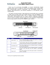
GAS INTAKE
A-G Installation elbow
B Wall Valve
C-D Three-piece union fitting
(minimum 1 per installation)
E-F End connector for the flexible tube
H Marking line
DANGER
Installation, air adjustment and/or
service work must be in accordance
with all local codes and must be
performed by a certifi ed service
technician qualifi ed to work on
gas appliances.
DANGER
DO NOT store or use gasoline or other
fl ammable vapors or liquids in the
vicinity of this or any other appliance.
DANGER
NE PAS entreposer ni utiliser
d'essence ou d'autres vapeurs ou
liquides infl ammables à proximité de
cet appareil ou de tout autre appareil.

COMBITOUCH
TM
ESG SERIES • GAS INSTALLATION MANUAL • 18.
INSTALLATION
GAS SUPPLY & INSTALLATION
The minimum size requirement for gas piping or a
flexible connector is 3/4 - inch (19mm). For long runs
of gas piping, the pipe diameter must conform to the
tables in the National Fuel Gas Code, ANSI/NFPA
Z223.1.
A listed gas shut-off valve must be installed
upstream of the appliance to shut off the gas
supply during servicing. The shut-off valve should
be accessible with the appliance in the normal
installation position.
If the oven or the oven stand is supplied with
casters, gas connection must be made with a flexible
connector that complies with the Standard for
Connectors for Movable Gas Appliances, ANSI
Z21.69; or in Canada, Connectors for Movable Gas
Appliances, CAN/CGA-6.16-M87. When using a
flexible connector, a quick disconnect device must
be used to comply with the Standard for Quick-
Disconnect Devices for Gas Fuels, ANSI Z21.41; or in
Canada, Quick Disconnect Devices for Use with Gas
Fuels, CAN1-6.9.
When a quick disconnect device and flexible
connector are used, a restraining device must be
installed to limit the movement of the appliance and
prevent damage to the connector or quick disconnect.
An example of a restraining device would consist
of a 2000 pound test, stainless steel cable, attached
to a structural member of the kitchen wall behind
the oven. The means of attachment should consist
of a quick connect snap so that the oven can be
disconnected when the appliance must be moved
away from the wall.
The other end of the cable should be permanently
attached to the rear frame of the oven. The cable
should be of sufficient length so that no strain is ever
placed on the flexible gas connector in the event of
accidental movement of the oven without properly
disconnecting the gas connector. The flexible
connector should be routed to form a downward
“U” loop between the building gas supply and the
permanent attachment at the rear of the oven.
The routing of the flexible connector must not be
made under the oven. Oven temperatures achieved
during operation are too hot for safe operation. Gas
piping should be installed from the point of gas
connection at the bottom, front of the oven to the
back of the oven where the flexible connector may be
safely used. See the illustration for the recommended
placement.
WARNING
GAS PIPING MUST NEVER
BE INSTALLED TO RUN
UNDER THE BURNER
.
1/33