Parasound Halo Integrated Owner's manual
- Category
- Headphone amplifiers
- Type
- Owner's manual

Halo Integrated
2.1 Channel Integrated Amplifier and DAC
OWNER’S GUIDE
™

2
Important Safety Instructions
The lightning flash with the arrowhead symbol within an equilateral triangle is intended to alert the user to the presence of
“dangerous voltage” inside the product that may constitute a risk of electric shock.
The exclamation point within an equilateral triangle is intended to alert the user to the presence of important operating
and maintenance instructions in the literature accompanying the product.
TO REDUCE THE RISK OF ELECTRIC SHOCK, DO NOT REMOVE COVER. NO USER-SERVICEABLE PARTS
INSIDE. REFER SERVICING TO QUALIFIED SERVICE PERSONNEL
1. Read Instructions — Read all the safety and operating instructions before operating this product.
2. Retain Instructions — Retain safety and operating instructions for future reference.
3. Heed Warnings — Adhere to all warnings on the product and in the operating instructions.
4. Follow Instructions — Follow all operating and use instructions.
5. Cleaning — Unplug this product from the wall outlet before cleaning. Use a damp cloth for cleaning. Clean the
outside of the product only.
6. Attachments — Do not use attachments that are not recommended by the product manufacturer; they may be
hazardous.
7. Water and Moisture — Do not use this product near water.
8. Accessories — Do not place this product on an unstable cart or stand. The product may fall, causing bodily injury
and damage to the product. A product and cart combination should be moved with care. Quick stops, excessive force,
and uneven surfaces may cause the product and cart to overturn.
9. Ventilation — Slots and openings in the cabinet are provided for ventilation to ensure reliable operation of the
product and to protect it from overheating. These openings must not be blocked or covered. This product should not be
placed in a built-in installation such as a bookcase or rack unless proper ventilation is provided.
10. Power Sources — Operate this product only from the type of power source indicated on the label. If you are not
sure of the type of power supply to your home, consult your dealer or local power company. This product is equipped with
a three-prong grounding plug. This plug will only fit into a grounding power outlet. If you are unable to insert the plug into
the outlet, contact your electrician to replace your obsolete outlet. Do not defeat the safety purpose of the grounding plug.
11. Power Cord Protection — Power supply cords should be routed so that they are not likely to be walked on or
pinched by items placed upon or against them.
12. Lightning — Unplug the unit from the wall outlet for added protection during a lightning storm and when it is left
unattended and unused for long periods of time. This will prevent damage to the product due to lightning and power line
surges.
13. Overloading — Do not overload wall outlets or extension cords. This can result in a fire or electric shock.
14. Inserting Objects into Unit — Never push objects of any kind into this product through any openings; they may
touch dangerous voltage points or short out parts that could result in fire or electric shock.
15. Servicing — Do not attempt to repair or service this product yourself. Opening or removing covers may expose you to
dangerous voltage and other hazards. Refer all servicing to qualified service personnel.
16. Damage Requiring Service — Unplug this product from the wall outlet and refer servicing to qualified
service personnel under the following conditions: a) If the power-supply cord or plug is damaged.
b) If liquid has been spilled into the product. c) If the product has been exposed to rain or water. d) If the product does not
operate normally by following the operating instructions. e) If the product has been dropped or damaged in any way. f) If
the product exhibits a distinct change in performance.
17. Replacement Parts — When replacement parts are required, be sure the service technician has used replacement
parts specified by the manufacturer. Unauthorized substitutions may result in fire, electric shock, and other hazards.
18. Safety Check — Upon completion of any service or repairs to this product, ask the service technician to perform
safety checks to determine that the product is in proper operating condition.
19. Wall or Ceiling Mounting — Mount the product to a wall or ceiling only as recommended.
20. Heat — The product should be situated away from heat sources such as radiators, heat registers, stoves, and other
products (including amplifiers) that produce heat.

3
Table of Contents
Introduction . . . . . . . . . . . . . . . . . . . . . . . . . . . . . . . . . . . . . . . . . . . . . . . . . 4
Placement and Ventilation Guidelines . . . . . . . . . . . . . . . . . . . . . . . . . . . . . 5
Rack Mounting . . . . . . . . . . . . . . . . . . . . . . . . . . . . . . . . . . . . . . . . . . . . . . . 5
AC Mains Voltage . . . . . . . . . . . . . . . . . . . . . . . . . . . . . . . . . . . . . . . . . . . . . 6
Analog Audio Input Connections . . . . . . . . . . . . . . . . . . . . . . . . . . . . . . . . . 7
Theater Bypass / Amp Input . . . . . . . . . . . . . . . . . . . . . . . . . . . . . . . . . . . . 9
Digital Audio Inputs . . . . . . . . . . . . . . . . . . . . . . . . . . . . . . . . . . . . . . . . . . 11
USB Computer Setup . . . . . . . . . . . . . . . . . . . . . . . . . . . . . . . . . . . . . . . . . 12
Audio Output Connections . . . . . . . . . . . . . . . . . . . . . . . . . . . . . . . . . . . . . 13
Other Rear Panel Connections . . . . . . . . . . . . . . . . . . . . . . . . . . . . . . . . . . 14
Subwoofer Setup . . . . . . . . . . . . . . . . . . . . . . . . . . . . . . . . . . . . . . . . . . . . 15
Crossover Setup. . . . . . . . . . . . . . . . . . . . . . . . . . . . . . . . . . . . . . . . . . . . . 15
Turn On Options. . . . . . . . . . . . . . . . . . . . . . . . . . . . . . . . . . . . . . . . . . . . . 17
Front Panel Controls. . . . . . . . . . . . . . . . . . . . . . . . . . . . . . . . . . . . . . . . . . 18
Remote Control Functions . . . . . . . . . . . . . . . . . . . . . . . . . . . . . . . . . . . . . 20
Amplifier Protection & On-Off Button Red Glow . . . . . . . . . . . . . . . . . . . . 21
Problem & Remedies . . . . . . . . . . . . . . . . . . . . . . . . . . . . . . . . . . . . . . . . . 22
If You Require Assistance or Warranty Repair . . . . . . . . . . . . . . . . . . . . . . 24
Specifications. . . . . . . . . . . . . . . . . . . . . . . . . . . . . . . . . . . . . . . . . . . . . . . 25

4
Introduction
Thank You for Choosing Parasound
Your new Parasound
®
Halo Integrated is an advanced 2.1 channel integrated amplifier that has
been designed for the highest performance for serious two channel music listening and ease of
integration with a surround sound system. The Halo Integrated is built to the extremely strict
quality and performance standards for which Parasound is renowned. We’re proud to offer you this
exceptional audio component that will bring you many years of enjoyment and dependability.
Because your new Halo Integrated amplifier performs at a higher level of sonic performance than
you may have expected we encourage you to read this entire manual to maximize your enjoyment.
We wish you many years of listening enjoyment.
-The Parasound Staff
Keeping Records for Future Reference
Record the serial number located on the back panel or bottom of your Halo Integrated in the space
below. Also note your Parasound Dealer’s name and telephone number. Your purchase receipt/bill
of sale is required to determine if your Halo Integrated is eligible for Parasound warranty service.
We recommend that you make an extra copy of your original purchase receipt/bill of sale and store
it inside the Halo Integrated’s carton.
Halo Integrated Amplifier Serial #: ______________ (5 digit number below the bar code)
Parasound Dealer: ___________________________________________________
Parasound Dealer Phone Number: ___________________
Date of Purchase: ______________________
Important Warranty information
There is no Parasound warranty for this unit if it was not purchased from an Authorized
Parasound Dealer. Investigate warranty coverage statements made by an unauthorized dealer
very carefully, as you will need to depend entirely upon your dealer, and NOT upon Parasound.
Unauthorized dealers lack the capability to make repairs or arrange for repairs of Parasound
equipment. A list of Authorized Parasound Dealers and detailed warranty information is available
at www.parasound.com or you can call 415-397-7100 between 9:00 am and 4 pm Pacific time.
A missing or altered serial number could indicate that this unit was re-sold by an unauthorized
dealer or is stolen merchandise. If this unit is missing its serial number or the serial number has
been altered, you should return it to your dealer immediately for a full refund.

5
Unpacking Your Halo Integrated & Placement
Guidelines
Unpacking Your Halo Integrated
Carefully remove your Halo Integrated from its shipping carton and locate the enclosed
accessories:
• AC power cord
• Two 12V trigger wires, one with mono 3.5mm mini plugs, one with a mono 2.5mm sub-mini
plug and a mono 3.5mm mini plug
• Remote Control with two AA batteries
• USB A to USB B cable for music playback from a computer
• Stereo audio cable with stereo 3.5mm mini plugs for using the front panel AUX input
While you are unpacking your Halo Integrated, inspect it thoroughly for possible shipping damage
and tell your Parasound dealer immediately if you find any evidence of shipping damage. This
would be a good time to make a copy of your sales receipt to store with the Halo Integrated’s
original packing.
Note: The Halo Integrated should be shipped only in its original carton set and foam packing
inserts. Please save and store both the inner and outer cartons and, most especially, the foam
packing inserts to protect the Halo Integrated if you have to move it or ship it. You may wish to flatten
the cardboard cartons to save room in storage after cutting the taped seams on the bottom flaps.
Placement Guidelines
The Halo Integrated will be easier to use and will last longer if you follow these simple guidelines:
• Use input and output cables that are long enough to leave some slack; that will enable you to
pull the Halo Integrated out of a cabinet to check or to change connections without
inadvertently disconnecting cables.
• Place your Halo Integrated where you can route input and output signal cables as far as
possible from any AC cords.
• Where signal cables must cross AC cords they should do so only at a 90° right angle.
Ventilation Requirements
• Always position the Halo Integrated horizontally.
•The Halo Integrated should not be stacked on top of a power amplifier.
• The Halo Integrated should not be placed in a completely enclosed cabinet.
Rack Mounting your Halo Integrated
With its four feet removed, the Halo Integrated’s front panel height occupies three rack spaces:
5.25” or 133mm. (A single standard rack space occupies 1.75” or 44.5mm vertical height.) For
mounting in a standard 19” equipment rack, you must use the Parasound HRA 3 rack mount kit
(purchased separately). The HRA 3 kit includes four bolts and eight plastic washers with raised
“shoulders.” Slide one washer onto each mounting bolt with its raised shoulder pointing toward the
panel hole. Insert the bolt through the hole and slide the other washer on the bolt with its raised
shoulder facing the rear side of the panel. The washers will sandwich the Halo Integrated panel
and the four mounting bolts to prevent metal-to-metal contact between the Halo Integrated
chassis, the equipment rack, and the other components mounted in the rack.
Note: Because of its high bias Class-A/AB design this amp can get very warm, even when no
music is playing. At least 4” (or 10cm) of free space must be left above the unit. Other
heat-producing components should not be positioned directly beneath the Halo Integrated.
Warning: Do not put the screws for the feet back into the bottom of the Halo Integrated without
the feet. If you inserts the screws without the feet they could touch internal electrical
circuitry and cause a short circuit and damage to the amp.

6
AC Mains Voltage Selection and Fuse
Check the 115V/230V Voltage switch before plugging in
the Halo Integrated’s AC mains power cord!
Make sure the 115V/230V Voltage Selector switch on the Halo Integrated’s back panel is set
for the correct AC line (mains) voltage before you plug in the power cord. It can be
seriously damaged if this switch is set for the wrong AC mains voltage.
In the 115 V position the Halo Integrated can safely operate with AC Line voltages between 110 V-
125 V which is correct for North America, including Mexico, and also in Taiwan. In some countries,
such as Brazil, AC voltages differ by region. Most other countries require setting it to 230 V. With
the 230 V setting the Halo Integrated can operate safely with AC line voltages between 220 V-250
V. If the AC Voltage Selector is changed the mains fuse value must also be changed.
Note: A Halo Integrated that has been damaged by connection to the incorrect
AC mains voltage is not covered by the Parasound warranty.

7
Analog Audio Input Connections
Always unplug your Halo Integrated's AC Mains power cord before making or changing any input,
output or trigger wire connections. Inserting or removing an input or output cable while the Halo
Integrated is turned on can result in a blast of sound that could damage your loudspeakers. Make
sure there is no strain or tension on any cables that could cause them to pull loose.
Phono Input
The Halo Integrated is equipped with a high quality phono stage. If you wish to connect a
turntable, set the Load/Cartridge switch to MM (moving magnet) or MC (100Ω or 47kΩ
moving coil), depending on your cartridge type. Select MM if you are not sure which type of
cartridge you have. If you use the MC setting with an MM cartridge the volume level will be
very high and distorted.
Note: Only a turntable can be connected to the Phono input.
Phono Load/Cartridge Switch
The Phono input has a three position load/cartridge selector switch. Select the switch position
that matches your turntable cartridge type. We recommend that you contact the cartridge
manufacturer if you are unsure which setting is best for your equipment. You may also try all
three settings and use the setting which sounds the best in your system and listening room.
.
MM is for moving magnet cartridges. It provides a 47k ohm load and the appropriate
gain for all MM cartridges. This is the most common cartridge type.
MC 100Ω is for most moving coil cartridges. It provides the higher gain required for even
very low output MC cartridges and a 100 ohm load that is ideal for the majority of MC
cartridges.
MC 47kΩ provides the appropriate gain for MC cartridges with an alternative 47k ohm
load. You can try both the 100Ω and 47kΩ settings to see which sounds best in your
system. The MC 47kΩ setting is also the load which Soundsmith™ and Grado™
recommend for their MI (moving iron) cartridges.
Note: If your turntable won’t reach adequate volume, or if it plays too loud, you have
selected the incorrect cartridge type. Don’t forget to connect the ground wire from your
turntable to the Phono GND (ground) terminal on the Halo Integrated.

8
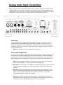
Analog Audio Input Connections (Continued)…
RCA line level Input Jacks (inputs 1-5)
Source inputs 1–5 all have the same input sensitivity and input impedance and they are
compatible with any typical analog line level source.
Note: Input 5 is shared with the XLR balanced input connectors, therefore the
RCA and XLR jacks for input 5 should not be connected at the same time.
XLR Balanced Input (input 5)
Input 5 also uses balanced XLR type jacks. Use this input to connect an analog source which
has balanced XLR outputs. A balanced line provides superior hum and noise cancellation,
especially for long cable runs.
Note: Input 5 is shared with the XLR balanced input, therefore the RCA and
XLR jacks for Input 5 should not be connected at the same time.
Front Panel Aux Input
For your convenience there is an input jack on the front panel for a portable MP3 player or
mobile phone. Connect the included cable with 3.5mm stereo plugs between your portable
player or phone’s headphone jack and the Halo Integrated’s Aux input jack. The Aux input has
an additional gain stage that boosts the input signal by 12dB so that the volume level remains
consistent when you select your other audio sources. For the best result set your portable
player or phone’s volume to at least 75% of its maximum level.
Note: If you connect a component other than a portable MP3 player or phone to the Aux
Input jack, the volume level will probably be too high and likely distorted.

9
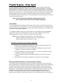
Theater Bypass / Amp Input
The Halo Integrated’s Bypass/Amp input makes it suitable for both the highest quality stereo
reproduction and for powering the L and R channels in a surround sound system. This unique
feature benefits your system in a number of ways. It will improve the performance of your left and
right speakers in a surround sound system because the power amp built into the Halo Integrated is
superior to any receiver’s amp. This will also relieve your receiver of the burden of driving the left
and right speakers so that more power is available to drive the center and surround channels.
This feature also enables your subwoofer(s) to operate with stereo sources and the sub channel(s)
in your surround sound system.
Note: In order to use the Halo Integrated’s Theater Bypass function
your surround sound receiver must have preamp output jacks.
How it Works
The Halo Integrated Theater Bypass function routes the incoming L and R (front) channels from
your surround receiver’s (or processor’s) L and R pre out jacks directly to the L and R inputs of its
power amp stage, bypassing the preamp stage. When the Halo Integrated is connected this way
it functions as a pure power amplifier.
The subwoofer output(s) from your surround receiver are routed directly from the Integrated’s
Bypass Sub In jacks to its Sub Output jacks. When you select the Bypass input the Halo
Integrated preamp circuits and controls are totally out of the signal path.
Note: The Halo Integrated must be turned on for the balanced XLR
outputs to function for the Bypass Input. This is because the XLR
balanced outputs require active driver circuitry.
All controls are removed from the Bypass signal path:
Adjusting the Halo Integrated’s Volume knob or remote control volume buttons will
not change the volume level of the Bypass input.
The Bass and Treble Tone controls do not function and frequency response is flat,
regardless of how these controls are adjusted.
The Left-Right Balance control does not function. L and R channel balance is equal,
regardless of how this control is adjusted.
The Pre and Speaker Outputs are full range, regardless of the Pre Out Crossover
settings.
The Sub Outputs are full range, regardless of the Sub Out Crossover settings.
The Surround Sound Receiver or Processor Stays in Control
The exclusions above are intentional so that your surround sound receiver volume control and
bass management menu settings are preserved when you are listening to surround sound with the
left, right and subwoofer channels routed through the Halo Integrated. Please see the owner’s
manual for your surround sound receiver to set and calibrate speaker levels, distance and bass
management. After adding the Halo Integrated to an existing surround sound system you should
recalibrate your system with the microphone that’s typically included with surround sound
receivers. Don’t forget that the volume control on the Halo Integrated will not work when the
Bypass Input is selected. Use the volume control on your surround sound receiver (or processor).

10
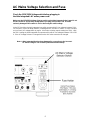
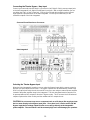
Connecting the Theater Bypass / Amp Input
Connect your surround sound receiver’s or processor's Left, Right & Sub(s) preamp output jacks
to the Halo Integrated’s Left, Right & Sub Bypass Input jacks. With a single subwoofer you can
use either the Sub 1 or Sub 2 Input jack. Connect your left and right speakers to the Left and
Right speaker output terminals on the Halo Integrated. Connect your subwoofer(s) to the
subwoofer outputs of the Halo Integrated.
Selecting the Theater Bypass Input
When the Halo Integrated is turned on you can select the Bypass input with the remote control or
with the front panel Input selector knob. The Bypass input will also be automatically routed to the
RCA Pre Output jacks when the unit is turned off in case you are using an external power amplifier
instead of the power amplifier stage in the Integrated. The Halo Integrated must be turned on for
its preamp balanced XLR outputs to function in Bypass mode. This is because the XLR balanced
outputs require active driver circuitry and the unbalanced RCA outputs do not.
CAUTION: Do not connect any source component such as a CD player, Blu-ray player, tape
deck or tuner directly to the Bypass Input jacks. Since there is no volume control with the
Bypass input the full voltage output from the source will go directly to the Integrated’s
power amplifier. The sound level could be extremely high and could damage your speakers.
Surround Sound Receiver or Processor
Halo Integrated

11
Digital Inputs: OPT, COAX, USB
The Halo Integrated’s built in 32 Bit DAC (Digital to Analog Converter) uses a very high resolution
384kHz ESS
®
Sabre32 Reference DAC IC. Since the Halo Integrated’s DAC is superior to the
DACs in most source components, they will sound better if you connect one of their digital outputs
to the Halo Integrated's DAC instead of connecting their analog output jacks.
Opt (Optical)
The Optical input is a high speed Toslink receiver. It accepts PCM digital signals up to
192kHz with 16 or 24 bit word lengths.
Optical Interconnect Note: 176.4kHz and 192kHz sampling rates will only play
reliably with a short optical cable. Be careful when handling the optical cable. It cannot
be bent at a sharp angle without impairing its ability to transfer the digital signal from
your source to the Halo Integrated.
Coax (Coaxial)
The Coax (also called S/PDIF) input connector is an RCA jack. It accepts PCM digital
signals up to 192kHz with 16 or 24 bit word lengths.
Coaxial Cable Note: A digital coaxial cable is different than a typical analog audio
cable. The Coax input works best with a true 75 ohm cable which typically has 75
ohm, RG6 or RG59 printed on the cable jacket. The use of ordinary audio cables can
make the signal unstable resulting in high levels of jitter, significantly impaired sound
and even audio dropouts.
USB – Windows
®
Users Must First Install Drivers
The USB input is used to connect your Halo Integrated to your Windows
®
PC or Mac
computer. This allows high quality playback of any music files that are stored on your
computer and streaming music services you access over the internet. The USB Input
accepts PCM sampling rates up to 384kHz with 16, 24 or 32 bit word lengths. The USB
input also accepts native DSD and DoP (DSD over PCM). The Halo Integrated uses USB
2.0 which requires Windows
®
users to first download and install drivers on their computer.
Please visit the Downloads section on the Halo Integrated’s web page www.parasound.com
for the Windows
®
drivers and installation instructions.
USB Cable Note: Inexpensive USB cables that are longer than 12’ (4m) are often
unreliable and could cause audio drop outs. If a longer USB cable is required, a
higher quality USB cable might offer more consistent results.
Using a Blu-ray, DVD Player or Gaming Console’s Digital Output
If you use a Blu-ray player, DVD player, cable TV box, satellite receiver or gaming console’s
digital output with the Halo Integrated you must go to the device's setup menu and set the digital
audio output to stereo PCM (2.0). The Halo Integrated’s DAC accepts only two-channel stereo
PCM. It does not accept signals in Dolby Digital or DTS formats.

12
USB - Computer Setup
For a Windows
®
PC
Windows users must first download and install the drivers before you can use the USB input. The
driver package and additional instructions can be found at www.parasound.com in the Downloads
section of the Halo Integrated’s web page.
After installing the drivers, connect the USB cable (included in the Halo Integrated accessories
carton) to your PC and then turn on the Halo Integrated. Next you will need to ensure that the
Halo Integrated is selected as the computer’s default audio output device. Follow these
instructions to assign the Halo Integrated as the default audio device:
1. Right click on the loudspeaker icon in the bottom right of your screen (on the tool bar)
2. Select “Playback Devices”
3. When the “Sound” window pops up click on the “PARASOUND - Digital Audio”
and then click “Set as Default”
4. Click “OK” to close the “Sound” window
Note: If for some reason you cannot find the loudspeaker icon you will need to select Sound
Options in the Control Panel and then select “PARASOUND - Digital Audio” as your
default playback device.
For a Mac
®
with OS X
Apple
®
computers do not require the installation of drivers to use the USB input. Connect the USB
cable (included in the Halo Integrated carton) to your Mac computer and then turn on the Halo
Integrated. Next you will need to ensure that the Halo Integrated is selected as the computer’s
default audio output device. Follow these instructions to assign the Halo Integrated as the default
audio device:
1. Go to the Apple menu
2. Select “System Preferences”
3. Select “Sound” from the Hardware menu
4. Select the “Output” tab
5. Select “PARASOUND - Digital Audio” in the Sounds menu
6. Close the Sounds menu
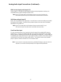
Playing Music from your Computer
Once initial setup is complete your Halo Integrated will be ready for use with your PC or Mac.
Press the USB button on the Halo Integrated’s remote control or rotate the Halo Integrated’s Input
select knob until the blue USB indicator is illuminated. Simply start playing any music on your
computer and it will be sent to the Halo Integrated via the USB cable. Any sound that you would
normally hear through your computer speakers will be heard through the Halo Integrated and your
accompanying audio system.
Note: For the highest quality sound playback we recommend leaving the computer application’s
volume control at 100%. Then use the volume control on your Halo Integrated to set the
listening level.

13
Audio Output Connections
Left and Right Speaker Outputs
The speaker binding posts will accept a wide variety of speaker wire and connectors including
large spade connectors, banana connectors and bare wire as large as 8 gauge. The binding
posts are spaced too far apart to accept older dual banana plug connectors with 3/4" (19mm)
spacing. This wider spacing is intentional so that larger spade type connectors can be used
without the risk of a short circuit.
Left and Right Pre Output Jacks (Balanced and Unbalanced)
The Pre Out jacks have the same preamp stage audio signal that goes to the power amp
stage. The Pre Out jacks are used for connecting an external power amplifier. An external
amp could be for bi-amping your speakers or for driving speakers in another room. Both RCA
(unbalanced) and XLR (balanced) outputs are provided and both types may be used at the
same time. If you are using two subwoofers in your system and wish them to be stereo (rather
than mono) you could also use the Left and Right Pre Output jacks, rather than the Sub Out
jacks for this purpose. If you are using stereo subs in this way, you would need the High Pass
Crossover switch to be set to Off.
Subwoofer Outputs (Balanced and Unbalanced)
The Halo Integrated provides one XLR connector and two RCA jacks for one or more
subwoofers. The two unbalanced and one balanced subwoofer outputs all carry the same
mono signal. You can select whether the mono signal is full range or crossed over according
to the frequency you select for the Low Pass crossover.
Using Stereo Subwoofers
If you have two subwoofers and want them to operate in stereo you can connect them to
the Left and Right Pre Out jacks instead of to the Sub Output jacks which are mono. In
this case you would need to set the High Pass crossover switch to Off. With this
configuration the front panel Sub Level control does not function.
Record Out Jacks
The Record Out jacks connect to your analog audio recorder’s record/input jacks. When you
select an input on the Integrated the signal from the corresponding source component is
available at the Record Out jacks whenever it is turned on. It is a fixed level signal that is
unaffected by volume, balance, tone settings, audio mute or crossover settings. The fixed
level Record Out jacks are also useful to connect a power amplifier for speakers in another
room that has a passive in-wall volume control.
Note: When you select the Bypass input, there is no signal available at the Record Out
jacks. The Halo Integrated does not offer simultaneous monitoring of a recording
while you are making it.

14
Other Rear Panel Connections
12V Input Jack
The 12V In jack is used to automatically turn the Halo Integrated on and off by an external
device. This input only functions when the Turn On Options switch is set to the 12V position.
When 12 volts is supplied to this jack the Halo Integrated will turn on and when the 12 volts is
removed it will turn off.
12V Output Jack
If you are using an additional power amplifier you may find it convenient for the Halo Integrated
to turn it on and off automatically. If your power amplifier is equipped with a 12 V trigger input,
connect the trigger cable (included) between the Halo Integrated’s 12 V Out jack and the
external amplifier’s 12 V trigger input. When the Halo Integrated is powered on, 12 volts will be
present at the 12 V output jack and your amp will turn on automatically.
IR Input Jack
Your Halo Integrated is compatible with most popular infrared repeater systems for remote
control operation from another room or when the Halo Integrated is installed in a cabinet where
its remote handset signals cannot reach its front panel remote control sensor. The External
Remote Input connector is a standard 1/8” (3.5mm) mono “mini” jack. The center conductor
(plug tip) is for signal and the outer conductor (plug sleeve) is for ground. Your Authorized
Parasound dealer or custom installer can recommend a compatible IR repeater system.
IR Loop Output Jack
The loop output offers a convenient way to daisy chain an IR signal to another piece of
equipment. Whatever IR control signal is present at the rear panel IR Input jack will also be
present at the IR Loop Out jack.
AC Power Cord
The AC cord supplied with your Halo Integrated is a high quality IEC type cord. If possible, plug
your Halo Integrated into the same AC outlet that your source components and power amplifier
are plugged into. If different AC outlets are used for the Halo Integrated and your other
components the ground potential may be higher or lower between the outlets, resulting in
audible hum.

15
Subwoofer Setup
The crossover setup and level setup are two important steps in setting up your sub(s).
Subwoofer Crossover Setup
You will want to turn off the crossover built into your subwoofer's amplifier since the Halo Integrated
has its own crossovers and leaving both the sub and Integrated’s crossovers on will result in double
filtering which restricts the sub output. Most powered subwoofers have a switch that might be
labelled “Bypass”, “Home Theater” or simply “Crossover Off.” If your subwoofer’s crossover cannot
be switched off, set it to its highest frequency. Follow the Crossover setup section for the proper
settings.
Subwoofer Level Setup
To set the proper subwoofer level, start with the Halo Integrated’s front panel Sub Level control set
to its 12 o’clock (0dB) position and then play a variety of music. Adjust the level control built into
your subwoofer until the bass level sounds balanced. Now, whenever you want to fine tune your
subwoofer level you can simply use the Halo Integrated's front panel Sub Level control instead of
walking over to your sub, bending down and reaching behind it to adjust its level control.
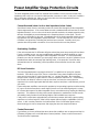
High and Low Pass Crossover Setup
The Halo Integrated is equipped with adjustable low pass
and high pass crossovers. Crossovers are filters that allow
certain frequencies to pass while blocking other
frequencies. A low pass filter permits low frequencies to
pass and blocks high frequencies. A high pass filter permits
only high frequencies to pass and blocks low frequencies.
80Hz is the best starting frequency for both the high and
low pass crossovers if you are using a subwoofer and are
not sure where to set the crossover frequency. If you are
not using a subwoofer, set the Pre Output Crossover switch
to the Off position. The Speaker Outputs and the Pre
Outputs (both RCA and XLR) are affected by the crossover
settings.
Low Pass Crossover (Subwoofer RCA and XLR Outputs)
The Low Pass crossover allows only low frequencies to be output from the Halo Integrated
Sub Output jacks.
Note: If your subwoofer has a built-in crossover that cannot be switched off, set it to
its highest frequency to minimize the negative effects on bass response from
filtering in the Halo Integrated and again in the subwoofer.
High Pass Crossover (Left and Right Speakers and Pre Outputs)
The High Pass crossover for the Speaker Outputs and Pre Outputs (both XLR and RCA)
allows you to prevent low frequencies from going to your main L and R speakers. This can be
particularly useful if you are using small speakers (typically their woofers are 6.5” (165mm) or
smaller and you have a subwoofer. The most common settings are between 50Hz and 80Hz.
If you are not using a subwoofer you will get the best results by turning the High Pass
crossover off or setting it below 40Hz. If you want your L and R speakers to operate full range
with no frequencies blocked set the High Pass crossover switch to its Off position.

16
Crossover Setup (Continued)…
Crossover On/Off Switches:
Sub Output Crossover Off
A full frequency range mono signal will be sent to the sub(s). You will need to
use the crossover frequency controls that are built into your subwoofer's
amplifier.
Sub Output Crossover On
The point where the highest frequency going to the Sub(s) starts to roll-off is
determined by the setting of the Low Pass frequency control.
Pre Output Crossover Off
Full Range signals will be sent to the left and right speakers and to the Pre
Output jacks.
Main Output Crossover On
The point where the lowest frequency going to the left and right speaker
terminals and the Pre Output jacks starts to roll off is determined by the
setting of the High Pass frequency knob.
Crossovers and the Bypass/Amp Input
The High and Low Pass Crossovers are always off when the Bypass Input is selected. In this
case the high and low pass filters are not active because it is preferable to use the bass
management you already selected in your surround sound receiver or processor's setup menu.
Where to Start with Crossover Settings
If you don’t know where to set the High and Low Pass Crossovers, these settings are a good place
to start. From here you can experiment until you find a combination that sounds best to you:
No subwoofer
Set the High Pass Crossover switch to Off
The Low Pass Crossover will not be used so this setting does not matter
When using one or more subwoofers and your Left and Right speakers'
woofers are 6.5” (165mm) or smaller
Set the High Pass Crossover switch to On and the Frequency knob to 80Hz
Set the Low Pass Crossover switch to On and the Frequency knob to 80Hz
When using one or more subwoofers and your Left and Right speakers'
woofers are larger than 6.5” (165mm)
Set the High Pass Crossover switch to On and the Frequency knob to 50Hz
Set the Low Pass Crossover switch to On and the Frequency knob to 50Hz

17
Turn On Options
For your convenience, there are three ways the Halo Integrated can be
turned on and off:
Manual - Press the On-Off button on the front panel or use the On and Off buttons on
the remote control.
Automatic (12V) - When 12 volts is applied to the 12V Input jack the Halo Integrated
will automatically power on.
Always On (AC) - Whenever the Halo Integrated’s AC power cord is plugged into a
live outlet it will be powered on.
Note: When either automatic turn on option is selected the front panel On-Off
button isdisabled so that power on/off is controlled solely by the triggering device
or live AC power.
Turn On Options Switch:
Manual Position
When the Turn On Options switch is in its Manual position, the Halo Integrated must be
turned on and off manually by pressing the front panel On-Off button or by using the
remote control’s On and Off buttons.
12V Position (Automatic On/Off)
When the Turn On Options switch is set to its 12V position, the Halo Integrated is
automatically powered on only when an external +9 to +12 volts is present at its 12V input
jack. When the external voltage ceases the Halo Integrated will turn off immediately. The 12V
switch position disables the front panel On-Off button and the remote control’s On and Off
buttons.
AC (Always On)
The Halo Integrated will turn on automatically when the AC mains electrical outlet it’s plugged
into is live.
Note: The Halo Integrated will turn off only when the AC mains outlet is switched
off. Pressing the On-Off button on the front panel or the On and Off buttons on the remote
control will not turn it off when AC (Always On) is selected.
Note: Whenever the Auto Turn On switch is set to 12 V or AC the On-Off button on the front
panel and the remote control’s On and Off buttons are disabled.
3.5mm Mini Jack and 2.5mm Sub-Mini Jacks
Some models of Parasound power amplifiers and preamplifiers use 2.5mm “sub-mini” 12 volt
trigger jacks. To connect the Halo Integrated with these models we include a trigger wire with a
3.5mm plug at one end and a 2.5mm plug at the other end.

18
Front Panel Controls
On-Off Button
Whenever the Halo Integrated is turned on, the soft blue glow behind its On-Off button will
change to red for a few seconds while its circuits stabilize. Then the red glow will be replaced
by a brighter blue glow to indicate normal operation. If the glow remains red after turn on or
while the amp is in use, it indicates that the protection circuits have been activated and no
sound will be heard from the speaker. The most common cause for the On-Off button to
remain red is a shorted speaker connection or the unit has overheated. See page 21 for more
details on the protection circuit.
Note: The front panel On-Off button and remote control On and Off buttons are
disabled when the rear panel Turn On Options switch is set to 12V or AC.
Headphone Output
The Halo Integrated is equipped with a dedicated high quality current-feedback headphone
amplifier based on the top grade Texas Instruments TPA6120A. This superior design allows
for an extremely high slew rate preventing odd order distortions which are responsible for
listening fatigue. The virtually instantaneous response to musical dynamics doesn’t raise the
noise floor or degrade the s/n ratio like typical headphone amps. The headphone amp circuit
was also designed with a low 10 ohms output impedance and high gain to drive headphones
rated up to 600 ohms.
The headphone jack accepts a 1/8” (3.5mm) stereo mini plug. The Left and Right Speaker
Outputs and the Preamp output jacks (RCA and XLR) are muted whenever a headphone plug
is inserted into this jack. The L and R Record out jacks are not muted.
CAUTION: Please note where the volume knob is set before unplugging your
headphones to avoid a sudden unexpected high level of sound that could
damage your speakers.
Aux Input Jack
For your convenience there is an input for a portable MP3 player or mobile phone on the front
panel. Connect the included cable with 3.5mm stereo plugs between the portable player or
phone’s headphone jack and the Halo Integrated’s Aux Input jack. The Aux input has an
additional gain stage that boosts the input signal by 12dB so that the volume level will remain
consistent as you listen to your other source components. For the best results set your
portable player’s volume to at least 75% of its maximum.

19
Front Panel Controls (Continued)…
Bass and Treble Control Knobs
These offer precision adjustment of tonal balance. You will find that very slight adjustments
can add a degree of warmth, richness, clarity and “air.” However, greater adjustments may
obscure musical detail, and even risk overloading your speakers. The Bass and Treble
controls are only active when the blue light surrounding the Tone button is illuminated. The
Bass and Treble controls affect the Speaker Outputs, Pre Outputs and the Subwoofer Outputs.
Tone Button
By pressing this button, you can turn off the Bass and Treble tone controls, thereby completely
bypassing the tone control circuitry. This will improve sonic purity by eliminating the small
amount of noise and distortion inherent in tone control circuits. The tone controls can also be
turned on and off from the remote control. The remote control does not adjust bass and treble
tone controls. It can only engage and disengage them.
Input Select Knob
Rotating the Input selector will cycle through all of the inputs. The front panel LED under each
input name indicates when it is selected.
Sub Level Knob
The Sub Level control knob adjusts the subwoofer level. The sub level can be adjusted
between -10dB and +10dB, relative to the L and R channels. When the knob is in the 12
o’clock position the sub level boost is 0dB. When you first set up your subwoofer you should
set this control to 12 o’clock (0dB) and then play some music. Adjust the level control built
into your subwoofer until it sounds balanced. Now, whenever you want to fine tune your
subwoofer level you can simply use the front panel Sub Level control instead walking over to
your sub and bending over to adjust the level control on the subwoofer.
Note: The Sub Level knob does not adjust the Sub level when the Bypass Input is selected.
Balance Knob
Adjusting left and right channel balance is helpful to compensate for speaker placement or
room acoustics.
Volume Knob
Your Halo Integrated uses a high quality potentiometer to adjust the master volume level. The
potentiometer is motorized for remote control use.
Mute Button
Pressing the Mute button once will mute the signal at all of the output jacks except the Record
Out. The Mute button glow will change from blue to red when mute is engaged. Press the
Mute button a second time to cancel mute. Mute is automatically canceled if you press the
volume up or down buttons on the remote.
Note: Mute is not canceled when you turn the front panel Volume knob. It is
cancelled only from the remote control buttons or by pressing the Mute
button a second time.

20
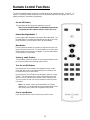
Remote Control Functions
The Halo Integrated remote control has a maximum range of approximately 20 - 25 feet (6 - 7.5
meters). Use only AA alkaline batteries in the handset and insert them according to the + and –
polarity markings in the battery compartment.
On and Off Buttons
These buttons will turn the Halo Integrated on and off.
Note: The On and Off buttons are disabled whenever the
rear panel Turn On Options switch is set to 12 V or AC.
Remote Backlight Button ☼
Pressing this button backlights the buttons with a blue glow. The
backlight will time-out after approximately 8 seconds or you may
press the button a second time to turn it off immediately.
Mute Button
Pressing the Mute button once mutes the signal at all of the Out
jacks except the Record Out. The Mute button on the front panel
will illuminate red while mute is engaged. Press the Mute button
a second time to cancel mute.
Volume ▲ and ▼ Buttons
These buttons control the rotation of the motorized Volume knob
to increase and decrease listening volume levels.
Tone On and Off Buttons
By pressing the Tone On button you engage the tone control
circuit with the boost or cut determined by your settings of the
front panel Bass and Treble knobs.
By pressing the Tone Off button you will bypass the tone control
circuits. This will improve sonic purity by eliminating the small
amount of noise and distortion inherent in tone control circuits.
The tone control circuits can also be turned on and off from the
front panel.
Note: The remote control cannot make Bass and Treble
adjustments. Tone adjustments are only made with the Bass
and Treble knobs on the Halo Integrated’s front panel.
Source Input Buttons
Press the input button of the source that you wish to hear.
Page is loading ...
Page is loading ...
Page is loading ...
Page is loading ...
Page is loading ...
Page is loading ...
-
 1
1
-
 2
2
-
 3
3
-
 4
4
-
 5
5
-
 6
6
-
 7
7
-
 8
8
-
 9
9
-
 10
10
-
 11
11
-
 12
12
-
 13
13
-
 14
14
-
 15
15
-
 16
16
-
 17
17
-
 18
18
-
 19
19
-
 20
20
-
 21
21
-
 22
22
-
 23
23
-
 24
24
-
 25
25
-
 26
26


Parasound Halo Integrated Owner's manual
- Category
- Headphone amplifiers
- Type
- Owner's manual
Ask a question and I''ll find the answer in the document
Finding information in a document is now easier with AI
Related papers
-
Parasound Zpre3 Owner's manual
-
Parasound JC 3 Jr. Owner's manual
-
-
-
-
-
-
-
Parasound HINT 6 Owner's manual
-
Parasound NewClassic 200 Pre Owner's manual