Page is loading ...

I-LS02110
Hager Companies
139 Victor Street
St. Louis, MO 63104
(800) 325-9995
(800) 782-0145 (FAX)
www.hagerco.com Rev 2, 8/16
34K1 & 34K2 SERIES
GRADE 1 CYLINDRICAL ELECTRONIC LOCK
INSTALLATION INSTRUCTIONS

I-LS02110
www.hagerco.com i Rev 2, 8/16
Table of Contents
A. CHECK LIST 1
- LOCK COMPONENTS 2
B. DOOR PREPARATION 3
C. FRAME PREPARATION 4
D. ADJUST FOR DOOR THICKNESS 5
E. LOCK HANDING 6
F. INSTALL LOCK HOUSING 8

I-LS02110
www.hagerco.com 1 Rev 2, 8/16
A. CHECKLIST (4 each AA Batteries Not Included)
Tools
Drill
Drill Bits: Ø1” (Ø31/32” for drive in latch), Ø13/16”, Ø3/8”, Ø5/16”
Hole Saw: Ø2-1/8”
Phillips Screwdriver, #2
Hammer
Chisel
Parts List: Each 34K1 & 34K2 Series lockset includes
• Exterior lock assembly (includes housing, lever and cylinder drive unit)
• Interior lock assembly
• Installation Instructions, I-LS02110
• Programming Manual, (I-LS02111 for 34K1, I-LS02139 for 34K2)
• Door Preparation Template, T-LS02112
• Hardware box includes:
- Electrified lock chassis assembly
- Interior lever + Steel ring
- Exterior rose/chassis mounting plate
- Interior rose/chassis mounting plate
- Latch bolt with deadlock
- 2 Keys
- ASA Strike
- Screw Pack includes:
(SB1) Phillips mounting screws M5 x 38mm x4pcs
(SB2) Flat head tapping screws #8x3/4" x2pcs
(SB3) Flat head tapping screws #12-24 x 1” x2pcs
(SB4) Lever release tool
(SB5) Phillips mounting screws M6 x 10mm x2pcs
(optional)
(SB6) Phillips mounting screws M5 x 25mm x2pcs
(SB1)
(SB2)
(SB3)
(SB4)
(SB5)
(SB6)

I-LS02110
www.hagerco.com 2 Rev 2, 8/16
LOCK COMPONENTS:
A. Battery Cover
B. Interior Housing Assembly
C. Interior Mounting Plate
D. Rubber Gasket
E. Electrified Lock Chassis Assembly
F. Exterior Housing Assembly
G. Cylinder Retainer
H. Exterior Lever
I. Interior Lever
J. Interior Rose Assembly
K. Interior Rose/Chassis Mntg Plate
L. Latch Bolt
M. Screw Post
N. Exterior Rose/Chassis Mntg Plate
O. Lock Cylinder
B. DOOR PREPARATION
1. Doors: Steel or Wood
2. Door thickness range: 1-3⁄8" (35mm) ~ 2" (51mm).
3. Match the Backset of your lockset to the corresponding installation (either 2-3⁄8" [60 mm] or 2-
3⁄4" [70 mm] Backset).
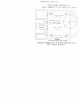
4. Place the installation template onto door and mark holes. Drill the Ø2 1⁄8" (54 mm) first, then
drill the two Ø5/16" (8mm) holes for lock chassis mounting followed by two Ø3/8" (9.5mm) holes
(A)
(B)
(C)
(D)
(E)
(F)
(G)
(H)
(I)
(J)
(L)
(K)
(M)
(N)
(O)

I-LS02110
www.hagerco.com 3 Rev 2, 8/16
for exterior Housing Assembly mounting. Drill the Ø13⁄16" (20 mm) hole for through wiring. Drill
the Ø1" (25 mm) cross bore hole for the latch last.
5. Insert latch into Ø1" hole and hold it parallel to door face, mark outline and remove latch. Chisel
11⁄64" (4.3mm) deep or until faceplate is flush with the edge of the door. Insert latch into the
Ø1" hole again, making certain that the latch bolt bevel faces direction of closing door (see
section E for Lock Handing).
6. Secure the latch to the door using two #8x3/4" screws (SB2).
C. FRAME PREPARATION
1. Close the door and mark the horizontal line aligned to the strike.
2. Measure one half of door thickness from door stop to mark vertical center line of strike. Drill Ø1"
(25 mm) hole, 1/2" (12.7 mm) deep at intersection of horizontal and vertical center lines.
3. Chisel out the jamb 3/32" (2.4mm) deep or until strike is flushed with jamb and then secure the
strike to the jamb using two #12-24 x 1” screws (SB3).
1)
2)
3)

I-LS02110
www.hagerco.com 4 Rev 2, 8/16
D. ADJUST FOR DOOR THICKNESS
Install exterior rose mounting plate onto the lock body by rotating it clockwise. Pay attention to the
installation direction of mounting plate’s anti-rotation tabs, they should be pointed toward the door.
1. Please follow the steps below:
a. Rotate exterior rose mounting plate toward cylindrical chassis.
b. Put the lever release tool into the allocated position of exterior rose mounting plate per the
illustration below.
c. Rotate exterior rose mounting plate to door thickness by using the lever release tool.
Lever Release Tool
Anti-Rotation Tabs on
the rose mounting plate

I-LS02110
www.hagerco.com 5 Rev 2, 8/16
E. LOCK HANDING
1. Determine the hand of your door. The product is set up for Right Hand by default.
INFORMATIONAL PURPOSES ONLY! NO ACTION REQUIRED!
Right Hand Door
Left Hand Door
Right Hand
Reverse Door
TOP VIEW
Left Hand
Reverse Door
INTERIOR
EXTERIOR
INTERIOR
EXTERIOR
TOP VIEW

I-LS02110
www.hagerco.com 6 Rev 2, 8/16
2. To change the handing to a left handed door, rotate the exterior and interior rose assemblies 180
degrees. The interior rose is handled in Step 6 on page 10. For the exterior rose, follow the steps
below:
(b). Remove the gasket to access the
four screws shown. Remove the
screws below and take out the exterior
rose assembly, rotating it 180 degrees
for a left handed door.
Re-install the four screws followed by
the gasket & lever to complete the
outside handing change.
(a). Remove the exterior lever
by turning the key 90° and
using the lever removal tool to
push in the catch pin. The
exterior lever catch pin is
facing the left side by default.
EXTERIOR ASSEMBLY
Exterior Rose Assembly

I-LS02110
www.hagerco.com 7 Rev 2, 8/16
F. INSTALL LOCK HOUSING
1. The lock body should have been adjusted for proper door thickness as shown in section D on
page 5.
2. Install lock body (a) into exterior housing. Be sure the lever rotation grooves line up with the
spindle on the lock body and the tailpiece inserts into the cam. Please insure the body is fully
seated.
3. Carefully insert the main cable through the Ø13/16” [20] wiring hole while installing the exterior
housing assembly on the door
Wiring Hole

I-LS02110
www.hagerco.com 8 Rev 2, 8/16
5. Install interior mounting plate with rubber gasket
a. Install interior mounting plate with rubber gasket using the two (SB6) M5 x 25mm
screws, routing the wires as shown on the first image on the next page. Leave screws
loose to adjust the plate.
b. Install (a) interior rose mounting plate using two (SB1) M5 x 38mm screws as shown in
the image on the following page for wire routing and handing.
c. It is very important to make sure the rose mounting plate is installed on the (b)
vertical center line, adjusting the mounting plate as necessary.
d. Verify that the exterior lever is rotating smoothly, and then tighten down the two (SB6)
M5 x 25mm screws
(SB6)
(SB1)
(a)
(b)
4. Remove the battery compartment cover to gain access to
the screws as shown below. Remove the interior escutcheon
from the interior mounting plate by removing the uncovered
screws as shown.
Route Wire
INTERIOR ASSEMBLY

I-LS02110
www.hagerco.com 9 Rev 2, 8/16
6. Install interior rose assembly using two (SB1) M5 x 38mm screws, routing the wire as shown. Be
sure that the rose assembly is installed in the correct direction for the handing of the
door. The lever catch pin should be facing the latch edge of the door.
7. Connect the cables to the inside of the (e) PCB while installing the interior housing. Install (c) the
interior housing assembly using three (d) M4 x 8mm screws previously removed in step 4.
(SB6)
(c)
(d)
(e)
Route Wire
Lever Catch /
Handing Pin
2P connector to power
cable (already
connected internally)
8P connector to main
cable
2P connector to lock
body cable
8P
2P

I-LS02110
www.hagerco.com 10 Rev 2, 8/16
8. Install (f) interior lever
9. READ THE CODE USER MANUAL BEFORE BEGINNING OPERATIONS.
a. Install four AA alkaline batteries in the (i) battery compartment
b. Install (g) battery cover using (h) M5 x 10mm screw previously removed in step 4
Troubleshooting Guide
Issue
Possible Fixes
Interior Lever Rubs
Remove interior lever
Loosen all three interior escutcheon mounting screws so the escutcheon can
move around
Reinstall interior lever
Push down on lever until it bottoms out (end of travel) and hold against stop
Tighten down all three escutcheon mounting screws
Move lever back up to home position
See where lever is rubbing on escutcheon
Remove interior lever & escutcheon
Remove interior spring cage
Loosen interior escutcheon mounting plate (see Section F, Paragraph 5)
o Shift plate in directions of binding (be careful to keep the Interior
Chassis Mounting Plate inside the cut out in the Interior Mounting Plate)
o Hold and tighten Interior Mounting Plate screws
Reinstall Interior Spring Cage
Reinstall Interior Escutcheon (leave screws loose)
Install lever
Position escutcheon to be centered on lever
Tighten mounting screws and check for binding in motion of lever
Chassis Does Not Install into External
Escutcheon (Step F)
Make sure removable mounting posts are fully seated in position
Make sure spindle grooves line up with bosses in spring cage / external
escutcheon
Make sure cam and tail piece line up for installation
(h)
(g)
(i)
(f)
/