
PM-65P LED-Backlit Display
User Manual
displays.agneovo.com

SAFETY INFORMATION ..................................................................................................... 1
REGULATORY INFORMATION ........................................................................................... 3
Federal Communications Commission (FCC) Notice (U.S. Only).............................................. 3
CE Declaration of Conformity..................................................................................................... 3
Polish Center for Testing and Certication Notice ...................................................................... 4
Electric, Magnetic and Electromagnetic Fields (“EMF”) ............................................................. 5
North Europe (Nordic Countries) Information ............................................................................ 6
End-of-Life Disposal ................................................................................................................... 6
Waste Electrical and Electronie Equipment-WEEE ................................................................... 7
CHAPTER 1: UNPACKING AND INSTALLATION...............................................................8
1.1 Unpacking ......................................................................................................................... 8
1.2 Package Contents ............................................................................................................ 8
1.3 Installation Notes .............................................................................................................. 8
1.4 Mounting on a Wall ........................................................................................................... 9
1.4.1 VESA Grid.............................................................................................................. 9
CHAPTER 2: PARTS AND FUNCTIONS .......................................................................... 11
2.1 Control Panel .................................................................................................................. 11
2.2 Input/Output Terminals .................................................................................................... 12
2.3 Remote Control ............................................................................................................... 13
2.3.1 General functions ................................................................................................ 13
2.3.2 ID Remote Control ............................................................................................... 14
2.3.3 Inserting the batteries in the remote control ........................................................ 15
2.3.4 Handling the remote control ................................................................................ 15
2.3.5 Operating range of the remote control ................................................................. 15
CHAPTER 3: CONNECTING EXTERNAL EQUIPMENT .................................................. 16
3.1 Connecting External Equipment (DVD/VCR/VCD) ......................................................... 16
3.1.1 Using COMPONENT video input ......................................................................... 16
3.1.2 Using Video Source input .................................................................................... 16
3.1.3 Using HDMI video input ....................................................................................... 17
3.2 Connecting a PC ............................................................................................................. 17
3.2.1 Using VGA input .................................................................................................. 17
3.2.2 Using DVI input .................................................................................................... 18
3.2.3 Using HDMI input................................................................................................. 18
3.2.4 Using DisplayPort input ....................................................................................... 18
3.3 Connecting Audio Equipment ......................................................................................... 19
3.3.1 Connecting external speakers ............................................................................. 19
3.3.2 Connecting an external audio device .................................................................. 19
3.4 Connecting Multiple Displays in a Daisy-chain Conguration ......................................... 19
3.4.1 Display control connection ................................................................................... 19
3.4.2 Digital video connection ....................................................................................... 20
3.4.3 Analog video connection ..................................................................................... 21
TABLE OF CONTENTS

3.5 IR connection .................................................................................................................. 21
3.6 IR Pass-through Connection ........................................................................................... 22
3.7 Wire-connecting to Network ............................................................................................ 22
CHAPTER 4: OPERATION ................................................................................................ 23
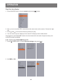
4.1 Watch the Connected Video Source ............................................................................... 23
4.2 Change Picture Format ................................................................................................... 23
4.3 Choose your Preferred Picture Settings ......................................................................... 23
4.4 Choose your Preferred Sound Settings .......................................................................... 23
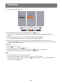
4.5 Play multimedia les via Local Area Network ................................................................. 24
4.5.1 Set up the network ............................................................................................... 24
4.5.2 How to use DLNA-DMP ....................................................................................... 24
4.5.3 How to use DLNA-DMR from PC......................................................................... 25
4.6 Play multimedia les from USB device ........................................................................... 27
4.7 Play options .................................................................................................................... 27
4.7.1 Playing music les ............................................................................................... 27
4.7.2 Playing movie les ............................................................................................... 28
4.7.3 Playing photo les ............................................................................................... 28
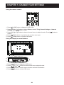
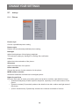
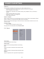
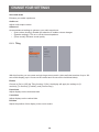
CHAPTER 5: CHANGE YOUR SETTINGS ....................................................................... 29
5.1 Settings ........................................................................................................................... 30
5.1.1 Picture.................................................................................................................. 30
5.1.2 Sound .................................................................................................................. 31
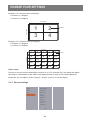
5.1.3 Tiling .................................................................................................................... 32
5.1.4 General settings .................................................................................................. 33
5.2 Network Settings ............................................................................................................. 39
CHAPTER 6: USB DEVICE COMPATIBILITY ................................................................... 40
6.1 USB device compatibility ................................................................................................ 40
CHAPTER 7: INPUT MODE .............................................................................................. 41
CHAPTER 8: TROUBLESHOOTING ................................................................................ 43
8.1 Troubleshooting .............................................................................................................. 43
CHAPTER 9: TECHNICAL SPECIFICATIONS ................................................................. 44
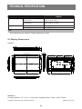
9.1 Display Specications ..................................................................................................... 44
9.2 Display Dimensions ........................................................................................................ 45
TABLE OF CONTENTS

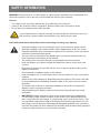
Safety precautions and maintenance
WARNING: Use of controls, adjustments or procedures other than those specied
in this documentation may result in exposure to shock, electrical hazards and/or
mechanical hazards.
Read and follow these instructions when connecting and using your display:
Operation:
• Keep the display out of direct sunlight and away from stoves or any other heat sources.
• Remove any object that could fall into ventilation holes or prevent proper cooling of the display’s
electronics.
• Do not block the ventilation holes on the cabinet.
• When positioning the display, make sure the power plug and outlet are easily accessible.
• When turning off the display by detaching the power cord, wait 6 seconds before re-attaching
the power cord for normal operation.
• Ensure the use of an approved power cord at all times. If your power cord is missing, please
contact your local service center.
• Do not subject the display to severe vibration or high impact conditions during operation.
• Do not knock or drop the display during operation or transportation.
Maintenance:
• To protect your display from possible damage, do not put excessive pressure on the LCD panel.
When moving your display, grasp the frame to lift; do not lift the display by placing your hand or
ngers on the LCD panel.
• Unplug the display if you are not going to use it for an extensive period of time.
• Unplug the display if you need to clean it with a slightly damp cloth. The screen may be wiped
with a dry cloth when the power is off. However, never use organic solvent, such as, alcohol, or
ammonia-based liquids to clean your display.
• To avoid the risk of shock or permanent damage to the set, do not expose the display to dust,
rain, water or an excessively moist environment.
• If your display becomes wet, wipe it with dry cloth as soon as possible.
• If a foreign substance or water gets in your display, turn the power off immediately and
disconnect the power cord. Then remove the foreign substance or water, and send the unit to
the maintenance center.
• Do not store or use the display in locations exposed to heat, direct sunlight or extreme cold.
• In order to maintain the best performance of your display and ensure a longer lifetime, we
strongly recommend using the display in a location that falls within the following temperature
and humidity ranges.
-
Temperature: 0-40°C 32-104°F
-
Humidity: 20-80% RH
IMPORTANT: Always activate a moving screen saver program when you leave your display
unattended. Always activate a periodic screen refresh application if the unit will display unchanging
static content. Uninterrupted display of still or static images over an extended period may cause
“burn in”, also known as “after-imaging” or “ghost imaging”, on your screen. This is a well-known
phenomenon in LCD panel technology. In most cases, the “burned in” or “after-imaging” or “ghost
imaging” will disappear gradually over a period of time after the power has been switched off.
1
SAFETY INFORMATION

WARNING: Severe “burn-in” or “after-image” or “ghost image” symptoms will not disappear and
cannot be repaired. This is also not covered under the terms of your warranty.
Service:
• The casing cover should be opened only by qualied service personnel.
• If there is any need for repair or integration, please contact your local service center.
• Do not leave your display under direct sunlight.
If your display does not operate normally, having followed the instructions set out in
this document, please contact a technician or your local service center.
Read and follow these instructions when connecting and using your display:
• Unplug the display if you are not going to use it for an extensive period of time.
• Unplug the display if you need to clean it with a slightly damp cloth. The screen
many be wiped with a dry cloth when the power is off. However, never use alcohol,
solvents or ammonia-based liquids.
• Consult a service technician if the display does not operate normally when you
have followed the instructions in this manual.
• The casing cover should be opened only by qualied service personnel.
• Keep the display out of direct sunlight and away from stoves or any other heat
sources.
• Remove any object that could fall into the vents or prevent proper cooling of the
display’s electronics.
• Do not block the ventilation holes on the cabinet.
• Keep the display dry. To avoid electric shock, do not expose it to rain or excessive
moisture.
• When turning off the display by detaching the power cable or DC power cord, wait
for 6 seconds before re-attaching the power cable or DC power cord for normal
operation.
• To avoid the risk of shock or permanent damage to the set do not expose the
display to rain or excessive moisture.
• When positioning the display, make sure the power plug and outlet are easily
accessible.
• IMPORTANT: Always activate a screen saver program during your application.
If a still image in high contrast remains on the screen for an extended period of
time, it may leave an ‘after-image’ or ‘ghost image’ on the front of the screen. This
is a well-known phenomenon that is caused by the shortcomings inherent in LCD
technology. In most cases the afterimage will disappear gradually over a period of
time after the power has been switched off. Be aware that the after-image symptom
cannot be repaired and is not covered under warranty.
SAFETY INFORMATION
2

Federal Communications Commission (FCC) Notice (U.S. Only)
This equipment has been tested and found to comply with the limits for a Class A
digital device, pursuant to part 15 of the FCC Rules. These limits are designed to
provide reasonable protection against harmful interference when the equipment is
operated in a commercial environment. This equipment generates, uses, and can
radiate radio frequency energy and, if not installed and used in accordance with
the instruction manual, may cause harmful interference to radio communications.
Operation of this equipment in a residential area is likely to cause harmful interference
in which case the user will be required to correct the interference at his own expense.
Changes or modifications not expressly approved by the party responsible for
compliance could void the user’s authority to operate the equipment.
Use only an RF shielded cable that was supplied with the display when connecting this display to a
computer device.
To prevent damage which may result in re or shock hazard, do not expose this appliance to rain or
excessive moisture.
THIS CLASS A DIGITAL APPARATUS MEETS ALL REQUIREMENTS OF THE CANADIAN
INTERFERENCE CAUSING EQUIPMENT REGULATIONS.
This device complies with part 15 of the FCC Rules. Operation is subject to the following
two conditions: (1) This device may not cause harmful interference, and (2) this device
must accept any interference received, including interference that may cause undesired
operation.
WARNING: This equipment is compliant with Class A of EN55032/CISPR 32. In a
residential environment this equipment may cause radio interference.
CE
3
REGULATORY INFORMATION

Polish Center for Testing and Certication Notice
The equipment should draw power from a socket with an attached protection circuit (a three-prong
socket). All equipment that works together (computer, display, printer, and so on) should have the
same power supply source.
The phasing conductor of the room’s electrical installation should have a reserve short-circuit
protection device in the form of a fuse with a nominal value no larger than 16 amperes (A).
To completely switch off the equipment, the power supply cable must be removed from the power
supply socket, which should be located near the equipment and easily accessible.
A protection mark “B” conrms that the equipment is in compliance with the protection usage
requirements of standards PN-93/T-42107 and PN-89/E-06251.
REGULATORY INFORMATION
4

Electric, Magnetic and Electromagnetic Fields (“EMF”)
1. We manufacture and sell many products targeted at consumers, which, like any electronic
apparatus, in general have the ability to emit and receive electromagnetic signals.
2. One of our leading Business Principles is to take all necessary health and safety measures for
our products, to comply with all applicable legal requirements and to stay well within the EMF
standards applicable at the time of producing the products.
3. We are committed to develop, produce and market products that cause no adverse health
effects.
4. We conrm that if its products are handled properly for their intended use, they are safe to use
according to scientic evidence available today.
5. We play an active role in the development of international EMF and safety standards, enabling
us to anticipate further developments in standardization for early integration in its products.
Information for U.K. only
WARNING - THIS APPLIANCE MUST BE EARTHED.
Important:
This apparatus is supplied with an approved moulded 13A plug.
To change a fuse in this type of plug proceed as follows:
1. Remove fuse cover and fuse.
2. Fit new fuse which should be a BS 1362 5A,A.S.T.A. or BSI
approved type.
3. Ret the fuse cover.
If the tted plug is not suitable for your socket outlets, it should
be cut off and an appropriate 3-pin plug tted in its place.
If the mains plug contains a fuse, this should have a value of 5A.
If a plug without a fuse is used, the fuse at the distribution board
should not be greater than 5A.
NOTES: The severed plug must be destroyed to avoid a
possible shock hazard should it be inserted into a 13A socket
elsewhere.
How to connect a plug
The wires in the mains lead are coloured in accordance with the
following code:
BLUE - “NEUTRAL” (“N”)
BROWN - “LIVE” (“L”)
GREEN & YELLOW - “EARTH” (“E”)
1. The GREEN & YELLOW wire must be connected to the
terminal in the plug which is marked with the letter “E” or by
the Earth symbol or coloured GREEN or GREEN & YELLOW.
2. The BLUE wire must be connected to the terminal which is
marked with the letter “N” or coloured BLACK.
3. The BROWN wire must be connected to the terminal which
marked with the letter “L” or coloured RED.
Before replacing the plug cover, make certain that the cord grip
is clamped over the sheath of the lead - not simply over the three
wires.
(A)
(B)
REGULATORY INFORMATION
5

設備名稱: 液晶彩色顯示器,型號(型式):PM-65P
單元
限用物質及其化學符號
鉛
(Pb)
汞
(Hg)
鎘
(Cd)
六價鉻
(Cr
+6
)
多溴聯苯
(PBB)
多溴二苯醚
(PBDE)
塑料外框 ○ ○ ○ ○ ○ ○
後殼 ○ ○ ○ ○ ○ ○
LCD panel - ○ ○ ○ ○ ○
電路板組件 - ○ ○ ○ ○ ○
底座 ○ ○ ○ ○ ○ ○
電源線 - ○ ○ ○ ○ ○
其他線材 - ○ ○ ○ ○ ○
遙控器 - ○ ○ ○ ○ ○
備考1.〝○〞係指該項限用物質之百分比含量未超出百分比含量基準值。
備考2.〝-〞係指該項限用物質為排除項目。
North Europe (Nordic Countries) Information
Placering/Ventilation
VARNING: FÖRSÄKRA DIG OM ATT HUVUDBRYTARE OCH UTTAG ÄR LÄTÅTKOMLIGA,
NÄR DU STÄLLER DIN UTRUSTNING PÅPLATS.
Placering/Ventilation
ADVARSEL: SØRG VED PLACERINGEN FOR, AT NETLEDNINGENS STIK OG
STIKKONTAKT ER NEMT TILGÆNGELIGE.
Paikka/Ilmankierto
VAROITUS: SIJOITA LAITE SITEN, ETTÄ VERKKOJOHTO VOIDAAN TARVITTAESSA
HELPOSTI IRROTTAA PISTORASIASTA.
Plassering/Ventilasjon
ADVARSEL: NÅR DETTE UTSTYRET PLASSERES, MÅ DU PASSE PÅ AT KONTAKTENE
FOR STØMTILFØRSEL ER LETTE Å NÅ.
End-of-Life Disposal
Your new Public Information Display contains materials that can be recycled and reused.
Specialized companies can recycle your product to increase the amount of reusable materials and
to minimize the amount to be disposed of.
Please nd out about the local regulations on how to dispose of your old display from your local
dealer.
(For customers in Canada and U.S.A.)
This product may contain lead and/or mercury. Dispose of in accordance to local-state and federal
regulations. For additional information on recycling contact www.eia.org (Consumer Education
Initiative)
REGULATORY INFORMATION
6

Waste Electrical and Electronie Equipment-WEEE
ttention users in European Union private households
This marking on the product or on its packaging illustrates that, under European
Directive 2002/96/EG governing used electrical and electronic appliances, this
product may not be disposed of with normal household waste. You are responsible
for disposal of this equipment through a designated waste electrical and electronic
equipment collection. To determine the locations for dropping off such waste electrical
and electronic, contact your local government ofce, the waste disposal organization
that serves your household or the store at which you purchased the product.
Attention users in United States:
Please dispose of according to all Local, State and Federal Laws. For the disposal or recycling
information, contact: www.mygreenelectronics.com or www.eiae.org.
End of Life Directives-Recycling
Your new Public Information Display contains several materials that can be recycled
for new users.
Please dispose of according to all Local, State, and Federal laws.
Restriction on Hazardous Substances statement (India)
This product complies with the “India E-waste Rule 2011” and prohibits use of lead, mercury,
hexavalent chromium, polybrominated biphenyls or polybrominated diphenyl ethers in
concentrations exceeding 0.1 weight % and 0.01 weight % for cadmium, except for the exemptions
set in Schedule 2 of the Rule.
E-Waste Declaration for India
This symbol on the product or on its packaging indicates that this product must not be
disposed of with your other household waste. Instead it is your responsibility to dispose
of your waste equipment by handing it over to a designated collection point for the
recycling of waste electrical and electronic equipment . The separate collection and
recycling of your waste equipment at the time of disposal will help to conserve natural
resources and ensure that it is recycled in a manner that protects human health and
the environ-ment.
Batteries
For EU: The crossed-out wheeled bin implies that used batteries should not be put to
the general household waste! There is a separate collection system for used batteries,
to allow proper treatment and recycling in accordance with legislation.
Please contact your local authority for details on the collection and recycling schemes.
For Switzerland: The used battery is to be returned to the selling point.
For other non-EU countries: Please contact your local authority for correct method of
disposal of the used battery.
According to EU directive 2006/66/EC, the battery can’t be disposed improperly. The battery shall
be separated to collect by local service.
Turkey RoHS
Türkiye Cumhuriyeti: EEE Yönetmeliğine Uygundur
REGULATORY INFORMATION
7

Ukraine RoHS
Обладнання відповідає вимогам Технічного регламенту щодо обмеження використання
деяких небезпечних речовин в електричному та електронному обладнанні, затвердженого
постановою Кабінету Міністрів України від 3 грудня 2008 № 1057
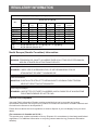
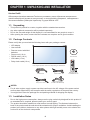
1.1. Unpacking
• This product is packed in a carton, together with the standard accessories.
• Any other optional accessories will be packed separately.
• Due to the size and weight of this display it is recommended for two people to move it.
• After opening the carton, ensure that the contents are complete and in good condition.
1.2. Package Contents
Please verify that you received the following items with your package content:
• LCD display
• User manual
• Remote control with AAA
batteries
• Power cord (1.8 m)
• RS232 cable (1.8 m)
• VGA cable (1.8 m)
• Daisy chain cable(1.8 m)
* The supplied power cord varies depending on destination.
Power Cord
User manual
Remote Control
and AAA Batteries
RS232 Cable
FORMAT
SOURCE
INFOLIST
OPTIONSADJUST
VOL
NORMAL
ID
ID SET ENTER
Video Signal Cable
(D-SUB to D-SUB Cable)
Daisy chain cable
NOTES:
• For all other regions, apply a power cord that conforms to the AC voltage of the power socket
and has been approved by and complies with the safety regulations of the particular country.
• You might like to save the package box and packing material for shipping the display.
1.3. Installation Notes
• Due to the high power consumption, always use the plug exclusively designed for this product. If
an extended line is required, please consult your service agent.
• The product should be installed on a at surface to avoid tipping. The distance between the
back of the product and the wall should be maintained for proper ventilation. Avoid installing the
product in the kitchen, bathroom or any other places with high humidity so as not to shorten the
service life of the electronic components.
CHAPTER 1: UNPACKING AND INSTALLATION
8

• The product can normally operate only under 3000m in altitude. In installations at altitudes
above 3000m, some abnormalities may be experienced.
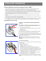
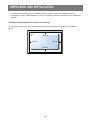
1.4. Mounting on a Wall
To mount this display to a wall, you will have to obtain a standard wall-mounting kit (commercially
available). We recommend using a mounting interface that complies with TUV-GS and/or UL1678
standard in North America.
Protective Sheet
VESA Grid
Table
1. Lay a protective sheet on a table, which was wrapped around the display when it was packaged,
beneath the screen surface so as not to scratch the screen face.
2. Ensure you have all accessories for mounting this display (wall mount, ceiling mount, table
stand, etc).
3. Follow the instructions that come with the base mounting kit. Failure to follow correct mounting
procedures could result in damage to the equipment or injury to the user or installer. Product
warranty does not cover damage caused by improper installation.
4. For the wall-mounting kit, use M6 mounting screws (having a length 10 mm longer than the
thickness of the mounting bracket) and tighten them securely.
5. Unit without base weight= 24.8 kg. The equipment and its associated mounting means still
remain secure during the test. For use only with UL Listed Wall Mount Bracket with minimum
weight/load: 24.8 kg.
6. Portrait is not allowed
1.4.1. VESA Grid
PM-65P
400(H) x 400(V) mm
Caution:
To prevent the display from falling:
• For wall or ceiling installation, we recommend installing the display with metal brackets which
are commercially available. For detailed installation instructions, refer to the guide received with
the respective bracket.
UNPACKING AND INSTALLATION
9

• To lessen the probability of injury and damage resulting from fall of the display in case of
earthquake or other natural disaster, be sure to consult the bracket manufacturer for installation
location.
Ventilation Requirements for enclosure locating
To allow heat to disperse, leave space between surrounding objects as shown in the diagram
below.
100 mm 100 mm
100 mm
100 mm
UNPACKING AND INSTALLATION
10

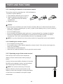
2.1. Control Panel
1 2 3 4 5 6 7 8
MUTE INPUT
MENU
9
1
[ ] Power button
Use this button to turn the display on or put
the display to standby.
2
[MUTE] button
Switch the audio mute ON/OFF.
3
[INPUT] button
Choose the input source.
• Used as [ ] button in the On-Screen-
Display menu.
4
[ ] button
Increase the adjustment while OSD menu is
on, or increase the audio output level while
OSD menu is off.
5
[ ] button
Decrease the adjustment while OSD menu is
on, or decrease the audio output level while
OSD menu is off.
6
[ ] button
Move the highlight bar up to adjust the
selected item while OSD menu is on.
7
[ ] button
Move the highlight bar down to adjust the
selected item while OSD menu is on.
8
[MENU] button
Return to previous menu while OSD menu is
on, or to activate the OSD menu when OSD
menu is off.
9
Remote control sensor and power status
indicator
• Receives command signals from the remote
control.
• Indicates the operating status of the display
without OPS:
-
Lights green when the display is turned
on
-
Lights red when the display is in standby
mode
-
Lights amber when the display enters
APM mode
-
If the light blinks red, it indicates that a
failure has been detected
-
Lights off when the main power of the
display is turned off
• Pull down the lens to have better remote
control performance and easy to observe
the light information of power status.
• Push up the lens before mounting the
display for video wall application.
• Pull/Push the lens until hearing the click
sound.
11
CHAPTER 2: PARTS AND FUNCTIONS

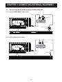
1
AC IN
AC power input from the wall outlet.
2
MAIN POWER SWITCH
Switch the main power on/off.
3
RS232C IN /
4
RS232C OUT
RS232C network input / output for the loop-
through function.
5
RJ-45
LAN control function for the use of remote
control signal from control center.
6
HDMI1 IN /
7
HDMI2 IN
HDMI video/audio input.
8
DVI IN
DVI-D video input.
9
DVI OUT / VGA OUT
DVI or VGA video output.
10
DisplayPort IN /
11
DisplayPort OUT
DisplayPort video input / output.
12
VGA IN (D-Sub)
VGA video input.
13
COMPONENT IN (BNC)
Component YPbPr video source input.
14
Y/CVBS
Video source input.
15
PC LINE IN
Audio input for VGA source (3.5mm stereo
phone).
16
SPEAKER SWITCH
Internal speaker on/off switch.
17
AUDIO IN
Audio input from external AV device (RCA).
18
AUDIO OUT
Audio output to external AV device.
19
USB PORT
Connect your USB storage device.
20
SPEAKERS OUT
Audio output to external speakers.
21
IR IN /
22
IR OUT
IR signal input / output for the loop-through
function.
NOTE:
• This display’s remote control sensor will stop
working if the jack [IR IN] is connected.
• To remotely control your A/V device via
this display, refer to page 22 for or IR Pass
Through connection.
23
OPS SLOT
Slot for installing the optional OPS module.
NOTE: We recommend to use Advantech
ARK-DS220B-D6A1E or Winmate OMIS-OPS
modules. We’ll not guarantee other OPS modules
24
SECURITY LOCK
Used for security and theft prevention.
2.2. Input/Output Terminals
1
2
16
7
3 5
8
9
15
6
23
4
10
14
11 12
13
24
17
19
22
20
18
21
PARTS AND FUNCTIONS
12

2.3. Remote Control
2.3.1 General functions
1
2
3
4
5
6
7
8
10
9
12
14
15
11
13
16
1
[POWER] button
Turn the display on or put the display to
standby.
2
[PLAY] buttons
Control playback of media les.
3
[ ] SOURCE button
Choose input source. Press
[ ]
or
[ ]
button
to choose from
USB
,
Network
,
HDMI 1
,
HDMI
2
,
DisplayPort
,
Card OPS
,
DVI-D
,
YPbPr
,
AV
, or
VGA
. Press
[ ]
button to conrm and exit.
4
[ ] HOME button
Access the OSD menu.
5
[ ] LIST button
No function.
6
[ ] [ ] [ ] [ ] NAVIGATION buttons
Navigate through menus and choose items.
7
[ ] button
Conrm an entry or selection.
8
[ ] ADJUST button
Access currently available options, picture and
sound menus.
9
[ ] MUTE button
Press to turn the mute function on/off.
10
[ ] [ ] [ ] [ ] COLOR buttons
Choose tasks or options.
11
[Number/ ID SET/ ENTER] button
Enter text for network setting.
Press to set the display ID. Refer to 2.3.2. ID
Remote Control for more detail.
12
[ ] FORMAT button
Change picture format.
13
[ ] BACK button
Return to the previous menu page or exit from
the previous function.
14
[ ] INFO button
Display information about current activity.
15
[ ] OPTIONS button
Access currently available options, picture and
sound menus.
16
[ ] [ ] VOLUME button
Adjust volume.
PARTS AND FUNCTIONS
13

2.3.2 ID Remote Control
You can set the remote control ID when you
want to use this remote control on one of
several different displays.
Press [ID] button. The red LED blinks twice.
1. Press [ID SET] button for more than 1 second
to enter the ID Mode. The red LED lights up.
Press the [ID SET] button again will exit the ID
Mode. The red LED lights off.
Press the digit numbers [0] ~ [9] to select the
display you want to control.
For example: press [0] and [1] for display No.1,
press [1] and [1] for display No.11.
The numbers available are from [01] ~ [255].
2. Not pressing any button within 10 seconds will
exit the ID Mode.
3. If an error pressing of buttons other than the
digits occured, wait 1 second after the red LED
lights off and then lights up again, then press
the correct digits again.
4. Press [ENTER] button to conrm. The red LED blinks
twice and then lights off.
NOTE:
• Press [NORMAL] button. The green LED
blinks twice, indicating the display is in normal
operation.
• It is necessary to set up the ID number for
each display before selecting its ID number.
PARTS AND FUNCTIONS
14

2.3.3 Inserting the batteries in the remote control
The remote control is powered by two 1.5V AAA batteries.
To install or replace batteries:
1. Press and then slide the cover to open it.
2. Align the batteries according to the (+)
and (–) indications inside the battery
compartment.
3. Replace the cover.
Caution:
The incorrect use of batteries can result in leaks or bursting. Be sure to follow these instructions:
• Place “AAA” batteries matching the (+) and (–) signs on each battery to the (+) and (–) signs of
the battery compartment.
• Do not mix battery types.
• Do not combine new batteries with used ones. It causes shorter life or leakage of batteries.
• Remove the dead batteries immediately to prevent them from liquid leaking in the battery
compartment. Don’t touch exposed battery acid, as it can damage your skin.
NOTE: If you do not intend to use the remote control for a long period, remove the batteries.
2.3.4 Handling the remote control
• Do not subject to strong shock.
• Do not allow water or other liquid to splash the remote control. If the remote control gets wet,
wipe it dry immediately.
• Avoid exposure to heat and steam.
• Other than to install the batteries, do not open the remote control.
2.3.5 Operating range of the remote control
Point the top of the remote control toward the
display’s remote control sensor when pressing a
button.
Use the remote control within a distance of less than
8m/26ft from the display’s sensor, and a horizontal
and vertical angle of less than 30 degrees.
NOTE: The remote control may not function
properly when the remote control sensor on the
display is under direct sunlight or strong illumination,
or when there is an obstacle in the path of signal
transmission.
30 30
PARTS AND FUNCTIONS
15

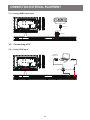
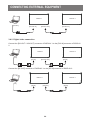
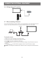
3.1 Connecting External Equipment (DVD/VCR/VCD)
3.1.1 Using COMPONENT video input
DVD / VCR / VCD
[AUDIO IN]
[COMPONENT IN]
(YPbPr)
COMPONENT Out
(YPbPr)
Audio Out
3.1.2 Using Video Source input
DVD / VCR / VCD
[Y/CVBS IN]
Y/CVBS Out
[AUDIO IN]
CHAPTER 3: CONNECTING EXTERNAL EQUIPMENT
16

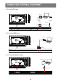
3.1.3 Using HDMI video input
DVD / VCR / VCD
HDMI Out
[HDMI IN]
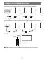
3.2 Connecting a PC
3.2.1 Using VGA input
PC
[VGA IN]
[VGA AUDIO IN]
VGA Out
D-Sub 15 pin
Audio Out
CONNECTING EXTERNAL EQUIPMENT
17
Page is loading ...
Page is loading ...
Page is loading ...
Page is loading ...
Page is loading ...
Page is loading ...
Page is loading ...
Page is loading ...
Page is loading ...
Page is loading ...
Page is loading ...
Page is loading ...
Page is loading ...
Page is loading ...
Page is loading ...
Page is loading ...
Page is loading ...
Page is loading ...
Page is loading ...
Page is loading ...
Page is loading ...
Page is loading ...
Page is loading ...
Page is loading ...
Page is loading ...
Page is loading ...
Page is loading ...
Page is loading ...
-
 1
1
-
 2
2
-
 3
3
-
 4
4
-
 5
5
-
 6
6
-
 7
7
-
 8
8
-
 9
9
-
 10
10
-
 11
11
-
 12
12
-
 13
13
-
 14
14
-
 15
15
-
 16
16
-
 17
17
-
 18
18
-
 19
19
-
 20
20
-
 21
21
-
 22
22
-
 23
23
-
 24
24
-
 25
25
-
 26
26
-
 27
27
-
 28
28
-
 29
29
-
 30
30
-
 31
31
-
 32
32
-
 33
33
-
 34
34
-
 35
35
-
 36
36
-
 37
37
-
 38
38
-
 39
39
-
 40
40
-
 41
41
-
 42
42
-
 43
43
-
 44
44
-
 45
45
-
 46
46
-
 47
47
-
 48
48


