Installation Manual 9
ENGLISH
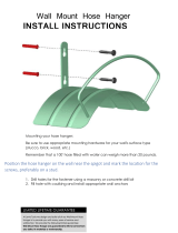
• Select and mark the position for fixing bolts
and piping hole.
• Decide the position for fixing bolts slightly
tilted to the drain direction after considering
the direction of drain hose.
• Drill the hole for anchor bolt on the wall.
CAUTION:
•
This air-conditioner uses a drain pump.
• Horizontly install the unit using a
level gauge.
•
During the installation, care should be
taken not to damage electric wires.
• Thoroughly study the following installation locations:
1. In such places as restaurants and kitchens, considerable amount of oil steam and flour
adhere to the turbo fan, the fin of the heat exchanger and the drain pump, resulting in heat
exchange reduction, spraying, dispersing of water drops, drain pump malfunction, etc.
In these cases, take the following actions:
• Make sure that the ventilation fan for smoke-collecting hood on a cooking table has
sufficient capacity so that it draws oily steam which should not flow into the suction of the
air conditioner.
• Make enough distance from a cooking room to install the air conditioner in such a place
where it may not suck in oily steam.
2. Avoid installing air conditioner in such circumstances where cutting oil mist or iron powder is
in suspension in factories, etc.
3. Avoid places where inflammable gas is generated, flows in, is stored or vented.
4. Avoid places where sulfurous acid gas or corrosive gas is generated.
5. Avoid places near high frequency generators.