VocoPro ENTERTAINER Owner's manual
- Category
- Karaoke systems
- Type
- Owner's manual

ENTERTAINER
The all in one Unit
owner's manual
13”
Color TV
, CD/CD+G Player AM/FM
T
uner, Dual Cassette Decks, Digital
Key Control Karaoke System

2
Safety Instructions
CAUTION
RISK OF SHOCK
CAUTION: To reduce the risk of electric shock,
do not remove cover (or back). No user-
serviceable parts inside. Only refer servicing to
qualified service personnel.
WARNING
To reduce the risk of fire or electric shock, do
not expose this unit to rain or moisture.
Explanation of Graphical Symbols
The lightning flash & arrowhead
symbol, within an equilateral triangle,
is intended to alert you to the
presence of danger.
The exclamation point within an
equilateral triangle is intended to alert
you to the presence of important
operating and servicing instructions.
1. Read Instructions - All the safety and operating
instructions should be read before the appliance is
operated.
2. Retain Instructions - The safety and operating
instructions should be retained for future reference.
3. Heed Warnings - All warnings on the appliance and in
the operating instructions should be adhered to.
4. Follow Instructions - All operating and use
instructions should be followed.
5. Attachments - Do not use attachments not
recommended by the product manufacturer as they may
cause hazards.
6. Water and Moisture - Do not use this unit near water.
For example, near a bathtub or in a wet basement and
the like.
7. Carts and Stands - The appliance should be used
only with a cart or stand that is recommended by the
manufacturer.
7 A. An appliance and cart combination
should be moved with care. Quick stops,
excessive force, and uneven surfaces may
cause an overturn.
8. Ventilation - The appliance should be situated so its
location does not interfere with its proper ventilation. For
example, the appliance should not be situated on a bed,
sofa, rug, or similar surface that may block the
ventilation slots.
9. Heat - The appliance should be situated away from
heat sources such as radiators, heat registers,
stoves, or other appliances (including amplifiers)
that produce heat.
10. Power Sources - The appliance should be
connected to a power supply only of the type described
in the operating instructions or as marked on the
appliance.
11. Grounding or Polarization – Precautions should be
taken so that the grounding or polarization means of
an appliance is not defeated.
12. Power-Cord Protection – Power-supply cords
should be routed so that they are not likely to be walked
on or pinched by items placed upon or against them,
paying particular attention to cords at plugs,
convenience receptacles, and the point where they exit
from the appliance.
13. Cleaning – Unplug this unit from the wall outlet
before cleaning. Do not use liquid cleaners or
aerosol cleaners. Use a damp cloth for cleaning.
14. Power lines – An outdoor antenna should be
located away from power lines.
15. Nonuse Periods – The power cord of the appliance
should be unplugged from the outlet when left unused
for a long period of time.
16. Object and Liquid Entry – Care should be taken so
that objects do not fall and liquids are not spilled into the
enclosure through openings.
17. Damage Requiring Service – The appliance should
be serviced by qualified service personnel when:
A. The power supply cord or plug has been damaged; or
B. Objects have fallen into the appliance; or
C. The appliance has been exposed to rain; or
D. The appliance does not appear to operate normally
or exhibits a marked change in performance; or
E. The appliance has been dropped, or the enclosure
damaged.
18. Servicing – The user should not attempt to service
the appliance beyond that described in the operating
instructions. All other servicing should be referred to
qualified service personnel.
NOTE:
To CATV system installer’s (U.S.A.): This reminder is
provided to call the CATV system installer’s attention to
Article 820-40 of the NEC that provides guidelines for
proper grounding and, in particular, specifies that the
cable ground shall be connected as close to the point of
cable entry as practical.

3
FCC INFORMATION (U.S.A.)
1. IMPORTANT NOTICE: DO NOT MODIFY THIS
UNIT! This product, when installed as indicated in
the instructions contained in this manual, meets
FCC requirements. Modifications not expressly
approved by Vocopro may void your authority,
granted by the FCC, to use this product.
2. IMPORTANT: When connecting this product to
accessories and/or another product use only high
quality shielded cables. Cable(s) supplied with this
product MUST be used. Follow all installation
instructions. Failure to follow instructions could
void your FCC authorization to use product in the
U.S.A.
3. NOTE: This product has been tested and found
to comply with the requirements listed in FCC
Regulations, Part 15 for Class “B” digital devices.
Compliance with these requirements provides a
reasonable level of assurances that your use of
this product in a residential environment will not
result in harmful interference with other electronic
devices. This equipment generates/uses radio
frequencies and, if not installed and used
according to the instructions found in the owner’s
manual, may cause interference harmful to the
operation of other electronic devices. Compliance
with FCC regulations does not guarantee that
interference will not occur in all installations. If this
product is found to be the source of interference,
which can be determined by turning the unit “Off”
and “On”, please try to eliminate the problem by
using one of the following measures:
Relocate either this product or the device that is
being affected by the interference.
Use power outlets that are on different branch
(circuit breaker or fuse) circuits or install AC line
filter(s).
In the case of radio or TV interference,
relocate/reorient the antenna. If the antenna lead-
in is 300-ohm ribbon lead, change the lead-in to
coaxial type cable.
If these corrective measures do not produce
satisfactory results, please contact your local
retailer authorized to distribute Vocopro products. If
you can not locate the appropriate retailer, please
contact Vocopro, 1728 Curtiss Court, La Verne, CA
91750.
CAUTION
The apparatus is not disconnected from the AC
power source so long as it is connected to the
wall outlet, even if the apparatus itself is turned
off. To fully insure that the apparatus is indeed
fully void if residual power, leave unit
disconnected from the AC outlet for at least
fifteen seconds.
CAUTION: READ THIS BEFORE
OPERATING YOUR UNIT
1. To ensure the finest performance, please read this
manual carefully. Keep it in a safe place for future
reference.
2. Install your unit in a cool, dry, clean place – away from
windows, heat sources, and too much vibration, dust,
moisture or cold. Avoid sources of hum (transformers,
motors). To prevent fire or electrical shock, do not
expose to rain and water.
3. Do not operate the unit upside-down.
4. Never open the cabinet. If a foreign object drops into
the set, contact your dealer.
5. Place the unit in a location with adequate air
circulation. Do not interfere with its proper ventilation;
this will cause the internal temperature to rise and may
result in a failure.
6. Do not use force on switches, knobs or cords. When
moving the unit, first turn the unit off. Then gently
disconnect the power plug and the cords connecting to
other equipment. Never pull the cord itself.
7. Do not attempt to clean the unit with chemical
solvents: this might damage the finish. Use a clean, dry
cloth.
8. Be sure to read the “Troubleshooting” section on
common operating errors before concluding that your
unit is faulty.
9. This unit consumes a fair amount of power even when
the power switch is turned off. We recommend that you
unplug the power cord from the wall outlet if the unit is
not going to be used for a long time. This will save
electricity and help prevent fire hazards. To disconnect
the cord, pull it out by grasping the plug. Never pull the
cord itself.
10. To prevent lightning damage, pull out the power cord
and remove the antenna cable during an electrical
storm.
11. The general digital signals may interfere with other
equipment such as tuners or receivers. Move the system
farther away from such equipment if interference is
observed.
12. When positining your equipment, especially
regarding speakers or other accessories, avoid
positioning them over areas where they can fall and
cause injury to yourself and others.
NOTE:
Please check the copyright laws in your country
before recording from records, compact discs, radio,
etc. Recording of copyrighted material may infringe
copyright laws.

4
Welcome….
Welcome….
And Thank you for purchasing the Entertainer from VocoPro, your ultimate choice in
Karaoke entertainment! With years of experience in the music entertainment business,
VocoPro is a leading manufacturer of Karaoke equipment, and has been providing
patrons of bars, churches, schools, clubs and individual consumers the opportunity to
sound like a star with full-scale club models, in-home systems and mobile units. All our
products offer solid performance and sound reliability, and to further strengthen our
commitment to customer satisfaction, we have customer service and technical support
professionals ready to assist you with your needs. We have provided some contact
information for you below.
VocoPro
1728 Curtiss Court
La Verne, CA 91750
Toll Free: 800-678-5348
TEL: 909-593-8893
FAX: 909-593-8890
VocoPro Company Email Directory
Customer Service & General Information
Tech Support
Remember Our Website
Be sure to visit the VocoPro website www.vocopro.com for the latest information on new
products, packages and promo’s. And while you’re there don’t forget to check out our
Club VocoPro for Karaoke news and events, chatrooms, club directories and even a KJ
Service directory!
We look forward to hearing you sound like a PRO, with VocoPro, your ultimate choice in
Karaoke entertainment.
FOR YOUR RECORDS
Please record the model number and serial number below, for easy reference, in case of loss or theft. These
numbers are located on the rear panel of the unit. Space is also provided for other relevant information
Model Number
Serial Number
Date of Purchase
Place of Purchase

5
Listening For A Lifetime
Selecting fine audio equipment such as the unit you’ve just purchased is only the start of
your musical enjoyment. Now it’s time to consider how you can maximize the fun and
excitement your equipment offers. VocoPro and the Electronic Industries Association’s
Consumer Electronics Group want you to get the most out of your equipment by playing it
at a safe level. One that lets the sound come through loud and clear without annoying
blaring or distortion and, most importantly, without affecting your sensitive hearing.
Sound can be deceiving. Over time your hearing “comfort level” adapts to a higher volume
of sound. So what sounds “normal” can actually be loud and harmful to your hearing. Guard
against this by setting your equipment at a safe level BEFORE your hearing adapts.
To establish a safe level:
• Start your volume control at a low setting.
• Slowly increase the sound until you can hear it comfortably and clearly, and without
distortion.
Once you have established a comfortable sound level:
• Set the dial and leave it there.
• Pay attention to the different levels in various recordings.
Taking a minute to do this now will help to prevent hearing damage or loss in the future.
After all, we want you listening for a lifetime.
Used wisely, your new sound equipment will provide a lifetime of fun and enjoyment. Since
hearing damage from loud noise is often undetectable until it is too late, this manufacturer
and the Electronic Industries Association’s Consumer Electronics Group recommend you
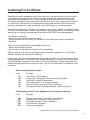
avoid prolonged exposure to excessive noise. This list of sound levels is included for your
protection.
Some common decibel ranges:
Level
30
40
50
60
70
80
Example
Quiet library, Soft whispers
Living room, Refrigerator, Bedroom away from traffic
Light traffic, Normal Conversation
Air Conditioner at 20 ft., Sewing machine
Vacuum cleaner, Hair dryer, Noisy Restaurant
Average city traffic, Garbage disposals, Alarm clock at 2 ft.
The following noises can be dangerous under constant exposure:
Level
90
100
120
140
180
Example
Subway, Motorcycle, Truck traffic, Lawn Mower
Garbage truck, Chainsaw, Pneumatics drill
Rock band concert in front of speakers
Gunshot blast, Jet plane
Rocket launching pad
-Information courtesy of the Deafness Research Foundation

6
ENTERTAINER
The all in one unit
Cautions and Warnings . . . . . . . . . . . . . . . . . . . . . . . . . . . . . . . . . . . . . . . . . . . .
Welcome . . . . . . . . . . . . . . . . . . . . . . . . . . . . . . . . . . . . . . . . . . . . .
Listening for a Lifetime . . . . . . . . . . . . . . . . . . . . . . . . . . . . . . . . . . . . . . . . . . . .
Features . . . . . . . . . . . . . . . . . . . . . . . . . . . . . . . . . . . . . . . . . . . . . . . . . . . . . . . .
Before Getting Started . . . . . . . . . . . . . . . . . . . . . . . . . . . . . . . . . . . . . . . . . . . . .
Front Panel Description and Functions . . . . . . . . . . . . . . . . . . . . . . . . . . . . . .
Top and Rear Panel Description and Functions . . . . . . . . . . . . . . . . . . . . . . . .
Remote Control Descriptions and Functions . . . . . . . . . . . . . . . . . . . . . . . . . .
Getting Connected. . . . . . . . . . . . . . . . . . . . . . . . . . . . . . . . . . . . . . . . . . . . .
Antenna/channels. . . . . . . . . . . . . . . . . . . . . . . . . . . . . . . .. . . . . . . . . . . . . . . . .
OSD Description and Functions . . . . . . . . . . . . . . . . . . . . . . . . . . . . . . . . . . . . .
Advanced Operation . . . . . . . . . . . . . . . . . . . . . . . . . . . . . . . . . . . . . . . . . . . . . .
Troubleshooting . . . . . . . . . . . . . . . . . . . . . . . . . . . . . . . . . . . . . . . . . . . . . .
Contents
2-3
4
5
7
8
9-11
12
13
14-15
16
17-18
19-23
24

7
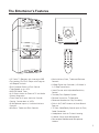
The Entertainer’s Features
• 13” Color TV Receiver with Interactive OSD
• Top Loading CD/CD+G Player with Program
and Repeat Controls
• Dual Cassette Decks w/Pitch Control
(Tape Speed) up to ±10%
• AM/FM Stereo Tuner
• A/V Output Jacks for External TV and Audio
System Integration
• Front Panel A/V Input Jacks for Console
Gaming, Camcorders or VCR’s
• 2 Microphone Inputs w/ Individual Volume
Controls
• Mic Bass, Treble and Echo Controls
• Music Volume, Bass, Treble and Balance
Controls
• 9-Step Digital Key Controller (± 2 Notes in
1/2 Step Increments)
• Vocal Partner with Adjustable Sensitivity
Control
• Two-Way Four Speaker System
• Remote Control for TV Operation
• Recessed Handles for Easy Portability
• Built-in VHF/UHF Antenna w/Auto-Search
Feature
• 75 Ohm Cable-Ready Coaxial Input for Easy
Cable Connection
• Headphones Jack for Private Listening
• 2 Metal Constructed Microphones
• Retractable Side-Mounted Microphone
Holders
PLAY
STOP PAUSE
SEARCH REPEAT
SKIP PROGRAM
POWER
OPEN
4 5 6
7 8 9
0 -/-- P.P
1
QV. LOGO DISP
2 3
X
X
MESS MENU
P+
P-
VOL+
VOL-

8
Before Getting Started: Things to Consider
It is very important to read the following instructions prior to starting any installation
procedures. Doing so will ensure a correct installation and may save you some time as well.
Protect Against Power Surges
• Connect all external components before you plug any of their power cords into the
wall outlet.
• Turn off the Entertainer before you connect or disconnect any cables.
• Make sure all antennas and cables are properly grounded.
Protect Components from Overheating
• Don’t block ventilation holes. Arrange any components so that air can circulate freely.
• Don’t stack components.
• If you place the Entertainer on a stand, make sure you allow adequate ventilation.
• If you connect an external receiver or amplifier, place it away from the Entertainer so the
heated air from it won’t flow around it.
Position Cables Properly to Avoid Audio Interference
• Insert each cable firmly into the designated jack.
• If you place components above the Entertainer, route all cables down the side of the back
of the Entertainer instead of straight down the middle of the back of the Entertainer.
• If your antenna uses 300-ohm twin lead cables, do not coil the cables. Also, keep the twin
lead cables away from audio/video cables.
Important Stand and Base Safety Information
Choose the location for your Entertainer carefully. If the Entertainer is placed on a stand or
base, ensure that it is of adequate size and strength to prevent it from being accidentally
tipped over, pushed off, or pulled off. This could cause personal injury and/or damage to the
Entertainer.
Use Indirect Light
Don’t place the Entertainer where sunlight or room lighting will be directed toward the
screen. Use soft or indirect lighting.
FCC Compliance Notice
This equipment has been tested and found to comply with the limits for a Class B digital
device, pursuant to Part 15 of the FCC Rules. These limits are designed to provide
reasonable protection against harmful interference when the equipment is operated in a
commercial environment. This equipment generates, uses and can radiate radio frequency
energy and, if not installed and used in accordance with the instruction manual, may cause
harmful interference to radio communications. Operation of this equipment in a residential
area is likely to cause harmful interference, in which case the user will be required to correct
the interference at his own expense.

CD+G
TV
AM FM ----- FM/ST
MASTER
VOLUME
MENU
DIGITAL KEY CONTROLLER
b #
L
L
LEFT RIGHT DOWN UP
REMOTE
SENSOR
TUNER
POWER PROGRAM
TV
TUNER
CD+G
AUX
TAPE
PLAY
REPEAT
MIC1 VOL
0 10 0 100 10 -10 +10 -10 +10
-10 +10 -10 +10 -10 +10MUSIC VOCALS MIN MAX
MIC2 VOL
MIC TREBLE
MIC BASS
ECHO
MUSIC TREBLE MUSIC BASS BALANCE PITCH
VOCAL
PARTNER
INPUT
SELECTOR
TAPE
AUX
TUNER
FM 88 90 92 94 96 98 100 102 104 106 108
AM 540 600 700 800 900 1000 1200 1400 1500 1600 1700
PRO DIGITAL ECHO
DIGITAL AUDIO
COMPACT
-4 -3 -2 -1 0 1 2 3 4
DECK 1 DECK 2
REC PLAY REW FFWD ST/EJ PAUSE
AUX
Y
MIC 1 MIC 2
W R PHONES
9
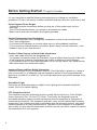
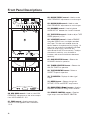
Front Panel Descriptions
1. AM/FM TUNER – Turn DIAL to tune in to a
radio broadcast channel.
2. AM/FM SCALE – Provides BAND
FREQUENCIES for station location.
3. BAND SELECTOR – Selects between
AM/FM/FM-ST frequency bands.
4. MASTER VOLUME – Used to control the
MASTER VOLUME for the system. Also used to
set a maximum level for remote controlled
volume changes in TV mode.
5. POWER (LED) indicator – Illuminates when
the MAIN POWER is ON.
6. PLAY (LED) indicator – Illuminates during
CD/CD+G playback.
7. REPEAT (LED) indicator – Blinks for
TRACK REPEAT mode; is steady for REPEAT ALL
mode.
8. TRACK DISPLAY (LED) indicator –
Displays the TRACK NUMBER of the currently
playing track.
9. PROGRAM (LED) indicator – Illuminates
when a PROGRAM selection is in progress.
10. TV (LED) indicator – Illuminates when the
TV TUNER is initiated.
11. TUNER (LED) indicator– Illuminates when
the AM/FM TUNER is initiated.
12. CD+G (LED) indicator – Illuminates when
the CD/CD+G played or initiated.
13. AUX (LED) indicator – Illuminates when an
AUXILIARY device in initiated.
14. TAPE (LED) indicator – Illuminates when a
CASSETTE tape playback.
15. TV SELECTOR button – Selects the TV
TUNER for operation.
16. CD+G SELECTOR button – Selects the
CD/CD+G player for operation.
17. MIC 1 VOL control – Used to control the
volume output from MIC CHANNEL 1.
18. MIC 2 VOL control – Used to control the
volume output from MIC CHANNEL 2.
19. MIC TREBLE control – Used to make HIGH
FREQUENCY adjustments to the volume output
from MIC CHANNELS 1 & 2.
1
2
4
5
6
7
8
9
10 11
14
13
12
15
16
17
18
19
3
PLAY REW FFWD ST/EJ PAUSE

CD+G
TV
AM FM ----- FM/ST
MASTER
VOLUME
MENU
DIGITAL KEY CONTROLLER
b #
L
L
LEFT RIGHT DOWN UP
REMOTE
SENSOR
TUNER
POWER PROGRAM
TV
TUNER
CD+G
AUX
TAPE
PLAY
REPEAT
MIC1 VOL
0 10 0 100 10 -10 +10 -10 +10
-10 +10 -10 +10 -10 +10MUSIC VOCALS MIN MAX
MIC2 VOL
MIC TREBLE
MIC BASS
ECHO
MUSIC TREBLE MUSIC BASS BALANCE PITCH
VOCAL
PARTNER
INPUT
SELECTOR
TAPE
AUX
TUNER
FM 88 90 92 94 96 98 100 102 104 106 108
AM 540 600 700 800 900 1000 1200 1400 1500 1600 1700
PRO DIGITAL ECHO
DIGITAL AUDIO
COMPACT
-4 -3 -2 -1 0 1 2 3 4
DECK 1 DECK 2
REC PLAY REW FFWD ST/EJ PAUSE
AUX
Y
MIC 1 MIC 2
W R PHONES
10
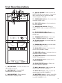
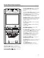
Front Panel Descriptions
20
21
30
31
32 33
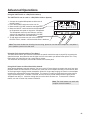
20. MIC BASS control – Used to make LOW
FREQUENCY adjustments to the volume output
from MIC CHANNELS 1 & 2.
21. ECHO control – Used to control the
amount of ECHO applied to MIC CHANNELS
1 & 2.
22. MUSIC TREBLE control – Used to make
HIGH FREQUENCY adjustments to music output.
23. MUSIC BASS control – Used to make
LOW FREQUENCY adjustments to music output.
24. BALANCE control – Used to balance
AUDIO OUTPUT between the L and R channels.
25. TAPE PITCH control – Used to adjust TAPE
SPEED (playback) ± 10%.
26. V.PARTNER control – Used to REMOVE
the guide VOCALS from a multiplex recorded
disc/tape. This feature is enabled when the
sensor detects microphone activity (singing). At
that time, the vocals are immediately removed.
When you stop singing, the vocals are
reintroduced to the mix automatically. To adjust
the sensor's sensitivity, turn clockwise to
increase, and counter-clockwise to decrease
sensitivity.
27. AUX SELECTOR button – Selects the
AUXILIARY device for operation.
28. TUNER SELECTOR button – Selects the
AM/FM TUNER for operation.
29. TAPE SELECTOR button – Selects a
CASSETTE tape for operation.
30. TV SCREEN – Displays all video signal
output.
31. MENU button – Selects through the
PICTURE, EXTRA and PRESET setup menus.
32. NAVIGATION ( ) buttons – Used to
NAVIGATE and SELECT though menu windows.
33. REMOTE CONTROL sensor – Receives
signal output from the REMOTE CONTROL.
22
23 24
25
26
27
28
29
PLAY REW FFWD ST/EJ PAUSE

CD+G
TV
AM FM ----- FM/ST
MASTER
VOLUME
MENU
DIGITAL KEY CONTROLER
b #
L
L
LEFT RIGHT DOWN UP
REMOTE
SENSOR
TUNNER
POWER PROGRAM
TV
TUNER
CD+G
AUX
TAPE
PLAY
REPEAT
MIC1 VOL
0 10 0 100 10 -10 +10 -10 +10
-10 +10 -10 +10 -10 +10MUSIC VOCALS MIN MAX
MIC2 VOL
MIC TREBLE
MIC BASS
ECHO
MUSIC TREBLE MUSIC BASS BALANCE PITCH
VOCAL
PARTNER
INPUT
SELECTOR
TAPE
AUX
TUNER
FM 88 90 92 94 96 98 100 102 104 106 108
AM 540 600 700 800 900 1000 1200 1400 1500 1600 1700
PRO DIGITAL ECHO
DIGITAL AUDIO
COMPACT
-4 -3 -2 -1 0 1 2 3 4
DECK 1 DECK 2
REC PLAY REW FFWD ST/EJ PAUSE
AUX
Y
MIC 1 MIC 2
W R PHONES
11
Front Panel Descriptions
34. KEY UP ( ) button – INCREASES the
MUSICAL KEY a 1/2 note each time it is pressed.
35. KEY NEUTRAL ( ) button – Returns the
musical key back to its neutral key.
36. KEY DOWN ( ) button – DECREASES
the MUSICAL KEY a 1/2 note each time it is
pressed.
37. -4 & +4 KEY (LED) indicators – Indicates
the musical KEY that the audio is playing in.
38. CASSETTE DECK 1 & 2 – Accepts audio
CASSETTE TAPES for cassette playback.
39. REC (•) button – Initiates a cassette tape
RECORDING when pressed simultaneously with
the PLAY button. Cassette recording is only
available on DECK 1.
40. PLAY ( ) button – Initiates a cassette
tape PLAYBACK.
41. REW ( ) button – Used to REWIND a
cassette tape.
42. F.FWD ( ) button – Used to FAST-
FORWARD a cassette tape.
43. STOP/EJECT ( ) button – Used to STOP
a cassette playback when pressed once, and
EJECT a cassette tape when pressed twice.
44. PAUSE ( ) button – Used to PAUSE a
cassette playback when pressed once, and
continue playback when pressed twice.
45. MIC 1 & 2 INPUT jacks – Connects a
MICROPHONE with 1/4” plugs.
46. AUX IN jacks – Connects an external A/V
device equipped with RCA-style A/V (L/R &
VIDEO) output.
47. HEADPHONES jack – Connects
HEADPHONES equipped with a 1/8” plug.
34 36
38
39
35
37
41
43
42
44
40
45 46 47
b
#
L
L
PLAY REW FFWD ST/EJ PAUSE

12
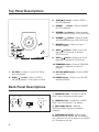
Top Panel Descriptions
Back Panel Descriptions
1 2
34
2
3 4
5
8
6
9
7
10
11
12
1
PLAY
STOP PAUSE
SEARCH REPEAT
SKIP PROGRAM
POWER
OPEN
3. STOP ( ) button – Press to STOP a
CD/CD+G playback.
4. PAUSE ( ) button – Press to PAUSE a
CD/CD+G playback.
5. SEARCH ( ) button – Press to rapidly
skip BACKWARD through a CD/CD+G track.
6. SEARCH ( ) button – Press to rapidly
skip FORWARD through a CD/CD+G track.
7. REPEAT button – Press to initiate a
REPEAT playback.
8. SKIP ( ) button – Press to go to the
beginning of the current or previous
CD/CD+G track.
9. SKIP ( ) button – Press to go to the
beginning of the next CD/CD+G track.
10. PROGRAM button – Press to PROGRAM
and initiate a selection of tracks for
playback.
11. CD TRAY OPEN button – Press to OPEN
the CD TRAY.
12. POWER button – Press to turn ON/OFF
the MAIN POWER.
1. AUDIO OUT jacks – Connects to AUDIO
INPUT jacks of an external audio system.
2. VIDEO OUT jack – Connects to a VIDEO
INPUT jack of an external TV or Monitor.
3. ANT/CABLE IN jack – Receives
ANTENNA/CABLE signals for broadcast
reception.
4. ANTENNA SELECTOR - Used to select
between the pull up antenna and 75Ω antenna
jack. Select INT for pull up antenna use, and EXT
for 75Ω antenna jack use.
Audio
Output
Video
Output
INT EXT
ANT/CABLE
75Ω
R L
1. CD TRAY – Accepts 3” and 5” CD/CD+G
discs for playback.
2. PLAY ( ) button – Press to START a
CD/CD+G playback. Press again to Pause.

13
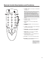
Remote Control Descriptions and Functions
4 5 6
7 8 9
0 -/-- P.P
1
QV. LOGO DISP
2 3
X
X
MESS MENU
P+
P-
VOL+
VOL-
1. VOLUME ± button – Used to adjust ± the MASTER
VOLUME level.
2. CHANNEL ± button – Used to move select ±
through TV channels.
3. MESS button – Used to view the MESSAGE
window.
4. NUMBER PAD buttons – Used to go directly to a
TV channel.
5. -/-- button – Used to specify a single or double digit
numeral for channel changes.
6. DISP button – Used to display current CHANNEL
and VOLUME status or clear a menu window.
7. MENU button – Used to enter the main MENU
window and execute a selection.
8. NAVIGATION buttons – Used to NAVIGATE and
SELECT though menu windows.
9. PP. button – Used to enter the PICTURE window.
10. QV. button – Used to go back and forth from the
current and previous TV channels.
Note: When making volume adjustments from the
remote control, remember that the maximum
volume will be governed by the setting of the
master volume knob. For example, if the master
volume knob is set to 25% the maximum volume
from the remote control will be 25%. If more volume
is needed, turn the master volume knob to a higher
position.
Note: Remote Control
functions are limited to
TV use only.
1
2
4
5
6
8
9
10
3 7

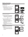
Getting Connected
Connecting a VCR, Camcorder
or Gaming Console
1. Connect the VCR/Camcorder/Game Console
to the Entertainer
A. Connect an A/V patch cable from the
AUDIO OUT/VIDEO OUT jacks on your
VCR/Camcorder/Game Console to the
AUX INPUT jacks located on the front
bottom panel of the Entertainer.
Connecting to an External Audio System
1. Connect the external audio system to the
Entertainer
A. Connect an RCA audio cable from the
AUDIO IN jacks on your external audio
system to the AUDIO OUT jacks on the
Entertainer.
Connecting to an External TV
1. Connect the external TV to the Entertainer
A. Connect an RCA video cable from the
VIDEO IN jack on your external TV to
the VIDEO OUT jack on the Entertainer.
Or
2. Connect the external TV to the Entertainer
through a RF Modulator (if TV is not
equipped with a video input jack)
A. Connect an RCA video cable from the
VIDEO OUT jack on the Entertainer to
the VIDEO IN jack on the RF
MODULATOR.
B. Connect ribbon leads from the RF
MODULATOR to the VHF ANTENNA IN
binding bolts.
Or
VCR/DVD Player
Gaming Console
Camcorder
Game
Audio & Video
Cable
white
yellow
red
white
yellow
yellow
red
white
y
e
l
l
o
w
w
h
i
t
e
red
r
e
d
14
TV
TV
Audio
Output
Video
Output
ANT/CABLE/75Ω
R L
Entertainer
Back Panel
Audio
Output
Video
Output
ANT/CABLE/75Ω
R L
Audio
Input
R L
Audio
Output
R L
Entertainer
Back Panel
Video In jack
RF
Modulator
AMPLIFIER
CD+G
TV
AM FM ----- FM/ST
MASTER
VOLUME
MENU
DIGITAL KEY CONTROLER
b #
L
L
LEFT RIGHT DOWN UP
REMOTE
SENSOR
TUNNER
POWER PROGRAM
TV
TUNER
CD+G
AUX
TAPE
PLAY
REPEAT
MIC1 VOL
0 10 0 100 10 -10 +10 -10 +10
-10 +10 -10 +10 -10 +10MUSIC VOCALS MIN MAX
MIC2 VOL
MIC TREBLE
MIC BASS
ECHO
MUSIC TREBLE MUSIC BASS BALANCE PITCH
VOCAL
PARTNER
INPUT
SELECTOR
TAPE
AUX
TUNER
FM 88 90 92 94 96 98 100 102 104 106 108
AM 540 600 700 800 900 1000 1200 1400 1500 1600 1700
ENTERTAINER
PRO DIGITAL ECHO
DIGITAL AUDIO
COMPACT
-4 -3 -2 -1 0 1 2 3 4
DECK 1 DECK 2
REC PLAY REW FFWD ST/EJ PAUSE
AUX
Y
MIC 1 MIC 2
W R PHONES
PLAY REW FFWD ST/EJ PAUSE
VCR/DVD Player
Gaming Console
Camcorder
Game
Audio & Video
Cable
white
yellow
red
white
yellow
yellow
red
white
y
e
l
l
o
w
w
h
i
t
e
red
r
e
d
CD+G
TV
AM FM ----- FM/ST
MASTER
VOLUME
MENU
DIGITAL KEY CONTROLER
b #
L
L
LEFT RIGHT DOWN UP
REMOTE
SENSOR
TUNNER
POWER PROGRAM
TV
TUNER
CD+G
AUX
TAPE
PLAY
REPEAT
MIC1 VOL
0 10 0 100 10 -10 +10 -10 +10
-10 +10 -10 +10 -10 +10MUSIC VOCALS MIN MAX
MIC2 VOL
MIC TREBLE
MIC BASS
ECHO
MUSIC TREBLE MUSIC BASS BALANCE PITCH
VOCAL
PARTNER
INPUT
SELECTOR
TAPE
AUX
TUNER
FM 88 90 92 94 96 98 100 102 104 106 108
AM 540 600 700 800 900 1000 1200 1400 1500 1600 1700
ENTERTAINER
PRO DIGITAL ECHO
DIGITAL AUDIO
COMPACT
-4 -3 -2 -1 0 1 2 3 4
DECK 1 DECK 2
REC PLAY REW FFWD ST/EJ PAUSE
AUX
Y
MIC 1 MIC 2
W R PHONES
PLAY REW FFWD ST/EJ PAUSE
CD+G
TV
AM FM ----- FM/ST
MASTER
VOLUME
MENU
DIGITAL KEY CONTROLER
b #
L
L
LEFT RIGHT DOWN UP
REMOTE
SENSOR
TUNNER
POWER PROGRAM
TV
TUNER
CD+G
AUX
TAPE
PLAY
REPEAT
MIC1 VOL
0 10 0 100 10 -10 +10 -10 +10
-10 +10 -10 +10 -10 +10MUSIC VOCALS MIN MAX
MIC2 VOL
MIC TREBLE
MIC BASS
ECHO
MUSIC TREBLE MUSIC BASS BALANCE PITCH
VOCAL
PARTNER
INPUT
SELECTOR
TAPE
AUX
TUNER
FM 88 90 92 94 96 98 100 102 104 106 108
AM 540 600 700 800 900 1000 1200 1400 1500 1600 1700
ENTERTAINER
PRO DIGITAL ECHO
DIGITAL AUDIO
COMPACT
-4 -3 -2 -1 0 1 2 3 4
DECK 1 DECK 2
REC PLAY REW FFWD ST/EJ PAUSE
AUX
Y
MIC 1 MIC 2
W R PHONES
PLAY REW FFWD ST/EJ PAUSE
Audio
Output
Video
Output
ANT/CABLE/75Ω
R L
Audio
Input
R L
Audio
Output
R L
AMPLIFIER
TV
Video In jack
Optional external
Antenna or cable TV jack
CD+G
TV
AM FM ----- FM/ST
MASTER
VOLUME
MENU
DIGITAL KEY CONTROLER
b #
L
L
LEFT RIGHT DOWN UP
REMOTE
SENSOR
TUNNER
POWER PROGRAM
TV
TUNER
CD+G
AUX
TAPE
PLAY
REPEAT
MIC1 VOL
0 10 0 100 10 -10 +10 -10 +10
-10 +10 -10 +10 -10 +10MUSIC VOCALS MIN MAX
MIC2 VOL
MIC TREBLE
MIC BASS
ECHO
MUSIC TREBLE MUSIC BASS BALANCE PITCH
VOCAL
PARTNER
INPUT
SELECTOR
TAPE
AUX
TUNER
FM 88 90 92 94 96 98 100 102 104 106 108
AM 540 600 700 800 900 1000 1200 1400 1500 1600 1700
ENTERTAINER
PRO DIGITAL ECHO
DIGITAL AUDIO
COMPACT
-4 -3 -2 -1 0 1 2 3 4
DECK 1 DECK 2
REC PLAY REW FFWD ST/EJ PAUSE
AUX
Y
MIC 1 MIC 2
W R PHONES
PLAY REW FFWD ST/EJ PAUSE

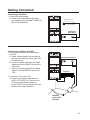
Getting Connected
Connecting a Cable Box
1. Connect the coaxial cable
A. Connect the coaxial cable provided by
your cable provider to the ANT./CABLE IN
jack on the Entertainer.
Connecting a Cable Box and VCR
1. Connect Signal Splitter to the Entertainer
and VCR
A. Obtain a Signal Splitter (not provided) to
split the signal coming into the room from
the cable source.
B. Connect a coaxial cable from the Signal
Splitter and to the CABLE IN jack on the
Entertainer.
C. Connect a coaxial cable from the Signal
Splitter to the ANTENNA IN jack on the
VCR.
2. Connect the TV to your VCR
A. Connect an A/V patch cable from the
AUDIO OUT/VIDEO OUT jacks on your
VCR/Camcorder/Game Console to
the AUX INPUT jacks located on the front
bottom panel of the Entertainer.
VCR Player
15
Audio
Output
Video
Output
ANT/CABLE/75Ω
R L
Entertainer
Back Panel
CD+G
TV
AM FM ----- FM/ST
MASTER
VOLUME
MENU
DIGITAL KEY CONTROLER
b #
L
L
LEFT RIGHT DOWN UP
REMOTE
SENSOR
TUNNER
POWER PROGRAM
TV
TUNER
CD+G
AUX
TAPE
PLAY
REPEAT
MIC1 VOL
0 10 0 100 10 -10 +10 -10 +10
-10 +10 -10 +10 -10 +10MUSIC VOCALS MIN MAX
MIC2 VOL
MIC TREBLE
MIC BASS
ECHO
MUSIC TREBLE MUSIC BASS BALANCE PITCH
VOCAL
PARTNER
INPUT
SELECTOR
TAPE
AUX
TUNER
FM 88 90 92 94 96 98 100 102 104 106 108
AM 540 600 700 800 900 1000 1200 1400 1500 1600 1700
ENTERTAINER
PRO DIGITAL ECHO
DIGITAL AUDIO
COMPACT
-4 -3 -2 -1 0 1 2 3 4
DECK 1 DECK 2
REC PLAY REW FFWD ST/EJ PAUSE
PLAY REW FFWD ST/EJ PAUSE
AUX
Y
MIC 1 MIC 2
W R PHONES
Antenna Cable jack
Audio
Output
Video
Output
ANT/CABLE/75Ω
R L
Entertainer Back Panel
CD+G
TV
AM FM ----- FM/ST
MASTER
VOLUME
MENU
DIGITAL KEY CONTROLER
b #
L
L
LEFT RIGHT DOWN UP
REMOTE
SENSOR
TUNNER
POWER PROGRAM
TV
TUNER
CD+G
AUX
TAPE
PLAY
REPEAT
MIC1 VOL
0 10 0 100 10 -10 +10 -10 +10
-10 +10 -10 +10 -10 +10MUSIC VOCALS MIN MAX
MIC2 VOL
MIC TREBLE
MIC BASS
ECHO
MUSIC TREBLE MUSIC BASS BALANCE PITCH
VOCAL
PARTNER
INPUT
SELECTOR
TAPE
AUX
TUNER
FM 88 90 92 94 96 98 100 102 104 106 108
AM 540 600 700 800 900 1000 1200 1400 1500 1600 1700
ENTERTAINER
PRO DIGITAL ECHO
DIGITAL AUDIO
COMPACT
-4 -3 -2 -1 0 1 2 3 4
DECK 1 DECK 2
REC PLAY REW FFWD ST/EJ PAUSE
AUX
Y
MIC 1 MIC 2
W R PHONES
Signal Splitter
Antenna
from Cable
Provider
Audio & Video
Cable
PLAY REW FFWD ST/EJ PAUSE

16
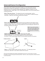
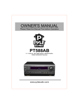
Antenna/Channel Configuration
When setting up the Entertainer for broadcast reception, you have three possible antenna
configurations to choose from depending on your preference and pre-existing accessories.
Remember that the UHF antenna is internal, therefore, UHF reception is standard with all the
configurations below. MAKE SURE TO SET THE ANTENNA SELECTOR on the rear panel prior to
connecting an antenna.
• Built-in Telescopic Antenna – The antenna that comes standard-equipped with the
Entertainer This antenna will receive VHF frequencies only and requires no additional wiring or
accessories. Select INT on the antenna selector for this antenna.
• External VHF Combo Antenna – These antennas can be purchased at most electronic stores.
They are usually equipped with a tuning dial and a gain booster on the receiver to better receive
broadcast reception. These antennas usually connect to the 75-Ohm coaxial jack. Select EXT on
the antenna selector for this antenna.
• Outdoor Antenna lead-in – These antenna lead-ins route from outdoor
antennas (usually roof-mounted) into homes via wall mounts. Usually they are
300-Ohm ribbon leads. To use this type of antenna you would need to obtain a
300-Ohm to 75-Ohm coaxial adapter. Select EXT on the antenna selector for this antenna.
• Cable-in – Standard Coaxial Cable-in provides cable access. The Cable plugs into the
Coaxial Jack. Select EXT on the antenna selector for this antenna.
Once you have decided which antenna configuration you will use, the next step is to set the
Entertainer's antenna setting to the correct position. To do this, refer to the previous Antenna section
in the Preset Menu.
Note: If you use this antenna
type, you will not be able to also
connect a coaxial cable line as
the coaxial jack will already be
in use.
CD+G
TV
AM FM ----- FM/ST
MASTER
VOLUME
TUNNER
POWER PROGRAM
TV
TUNER
CD+G
AUX
TAPE
PLAY
REPEAT
MIC1 VOL
0 10 0 100 10 -10 +10 -10 +10
-10 +10 -10 +10 -10 +10MUSIC VOCALS MIN MAX
MIC2 VOL
MIC TREBLE
MIC BASS
ECHO
MUSIC TREBLE MUSIC BASS BALANCE PITCH
VOCAL
PARTNER
INPUT
SELECTOR
TAPE
AUX
TUNER
FM 88 90 92 94 96 98 100 102 104 106 108
AM 540 600 700 800 900 1000 1200 1400 1500 1600 1700
Connect to
Entertainer
Outdoor Antenna lead-in

17
OSD Descriptions and Functions
Preset Menu
The PRESET menu allows you to select and setup your TV for broadcast channels, select an
antenna type, delete channel(s) from roster and perform a channel auto-search.
To enter the PRESET menu, hit the MENU button the Remote Control three times or press the
MENU button on the front panel three times. Use the NAVIGATION buttons to maneuver through
and execute from the possible settings.
Channel
The CHANNEL line is used to change the channel while the PRESET window is still superimposed
on the screen for adjustments.
Delete
The DELETE line is used to delete a channel from the channel roster. Use the CHANNEL line
(above) to find the channel you want to delete, then go to the DELETE line and press the RIGHT
arrow to delete it. To add a channel back to the channel roster, repeat the steps to delete channel.
Note: Even though a channel is deleted, you can still access it by manually entering the channel
with the NUMBER PAD.
Antenna
When setting up your antenna it is recomended to first set the Antenna Selector. (see pg 12).
The antenna line is used to select the antenna you are using to for broadcast reception. You can
choose from AIR or CABLE:
• AIR - Built in Antenna, external antenna lead-ins connected to 75-ohm jack.
• CABLE - For a cable-in lead from cable provider to 75-ohm jack only.
Auto Search
The Auto Search feature scans all channels available and determines whether or not the
frequency/channel is “active” and added to the channel roster. If available, the channel is
programmed and then selectable via the channel controls. If not deemed active, the channel will not
appear in the channel roster. You can still direct input the channel via the remote control, however
reception will not be satisfactory. It would then be recommended to reconfigure your antenna setup,
and repeat the channel search. Be sure to auto-search after an antenna configuration.
Note: Preset menu is only available when TV Function is selected on the Input Selector.

18
OSD Descriptions and Functions
Picture Menu
The PICTURE menu allows you to fine-tune the DISPLAY PROPERTIES for the TV screen. You
can either choose from the three presets: Hi-Bright, Mild and Natural, or customize your own setting
with the Memory setting.
To enter the PICTURE menu, hit the PP. button the Remote Control, or press the MENU button on
the front panel. Use the NAVIGATION buttons to maneuver through and execute from the possible
settings. To make a selection, press the RIGHT arrow.
Note: You can only customize the color, brightness, contrast, sharpness and tint properties in the
Memory screen.
Extra Menu
The EXTRA menu allows you to access the MESSAGE BOARD, CALENDAR and TETRIS/SNAKE
GAMES screens.
To enter the EXTRA menu, hit the MENU button the Remote Control twice or press the MENU
button on the front panel twice. Use the NAVIGATION buttons to maneuver through and execute
from the possible settings.
Message Board Screen
The Message Board screen allows you to program an alphanumeric text message that can appear
on-screen when selected. The message can be up 64 characters long (spaces included) with
available characters being: 0-9, A-Z, dashes, colons, periods and spaces. When programming the
message, the UP ARROW will move the cursor left, the DOWN ARROW will move the cursor right,
the LEFT and RIGHT ARROW’S select through the available characters. The text is saved
automatically upon exiting the message board screen.
Calendar Screen
The Calendar screen allows you select from the years of 1951-2050. Each year can be viewed by
month. This can be useful in long term planning and extrapolating historic dates. To maneuver, the
LEFT and RIGHT arrows move through the months, while the UP and DOWN arrows move through
the years.
Games (Tetris and Snake)
The Entertainer has two built-in Video Games that superimpose on the TV screen. For both the
TETRIS and SNAKE games, position the cursor to the game you wish to play and press the RIGHT
to start.
Note: In-game controls are displayed before the game is started.

19
CD/CD+G Playback Modes
1. REPEAT TRACK Mode – Repeat Track mode is used to continually repeat a single CD/CD+G track.
To enter Repeat Track mode, press the REPEAT button one (look for blinking light on the REPEAT LED).
To exit Repeat Track mode, press the REPEAT button twice more.
2. REPEAT ALL Mode – Repeat All mode is used to continually repeat ALL the tracks on a CD/CD+G disc.
To enter Repeat All mode, press the REPEAT button twice (look for the steady light on the REPEAT LED).
To exit Repeat All mode, press the REPEAT button once more.
3. PROGRAM Mode – Program mode is used to program a selection of tracks for consecutive playback.
To enter Program mode, press the PROGRAM button. You will see “Pr” blinking in the track display and a
blinking light in the PROGRAM LED. Press the button’s to maneuver through possible track
selections.
When you want to program a track, press the PROGRAM button. Repeat this process till you have
programmed all the desired tracks. To start the programmed playback, press PLAY. To exit the Program
Mode, press the PROGRAM button again.
2. Press the PLAY button.
4. To stop the CD/CD+G, press the STOP button. To PAUSE the CD/CD+G, press the ll button.
5. Press the button to SKIP backward through a CD/CD+G track and press the button
to SKIP forward through a CD/CD+G track.
6. To return to the PREVIOUS track, press the button, to advance to
the NEXT track press the track.
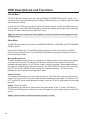
3. Adjust the MASTER VOLUME and
BALANCE controls to your pleasure.
Advanced Operations
3. Close CD tray.
2. Insert a CD/CD+G label side up.
1.A. Turn on the POWER
1.B. Set the input selector to CD/CD+G.
1. Press OPEN button.
CD/CD+G Playback
CD/CD+G Operation
Loading and Unloading CD/CD+G’s
Notes: To ensure firm locking of the CD tray, please press on the CD tray at the
LEFT MODE position until a 'click' sound is heard. Before operating the CD/CD+G
player for the first time, please make sure the neoprene bushing has been
removed from the CD tray. attempting to play a disc with the bushing still in
place can cause damage to the CD mechanism and disc.

20
Advanced Operations
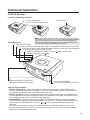
Note: To ensure firm locking of cassette holder/tape covers, please press the cassette door(s) at the center
point (or the rightmost positions) until a 'click' sound is heard.
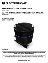
Cassette Operation
Loading and Unloading Cassettes
1. Press the STOP/EJECT button.
2. Insert a cassette tape with the desired
side facing you with tape surface down.
3. Close the cassette deck.
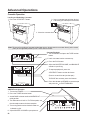
AM/FM Tuner Operation
1. Turn on the POWER.
2. Press the TUNER function button.
3. Switch BAND selector to either AM/FM/FM ST
radio position.
4. The AM antenna is built-in. For FM reception, use
the telescopic antenna for best reception.
5. Turn tuning knob to select desired station as
indicated on dial.
6. Adjust MASTER VOLUME to your pleasure.
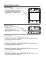
Cassette Playback
1. Turn on POWER and press the TAPE function
button.
2. Load a cassette into the cassette tray.
3. Press the PLAY button.
4. Adjust the MASTER VOLUME, and BALANCE
controls to your liking.
5. To stop tape playback, press the
STOP/EJECT button on that deck once.
(Press a second time to eject the tape.)
To PAUSE the cassette, press the ll button.
6. Press the button to REWIND a cassette tape
and press the to FAST-FORWARD.
side you
want to
Listen
CD+G
TV
AM FM ----- FM/ST
MASTER
VOLUME
TUNNER
POWER PROGRAM
TV
TUNER
CD+G
AUX
TAPE
PLAY
REPEAT
MIC1 VOL
0 10 0 100 10 -10 +10 -10 +10
-10 +10 -10 +10 -10 +10MUSIC VOCALS MIN MAX
MIC2 VOL
MIC TREBLE
MIC BASS
ECHO
MUSIC TREBLE MUSIC BASS BALANCE PITCH
VOCAL
PARTNER
INPUT
SELECTOR
TAPE
AUX
TUNER
FM 88 90 92 94 96 98 100 102 104 106 108
AM 540 600 700 800 900 1000 1200 1400 1500 1600 1700
DECK 1 DECK 2
REC PLAY REW FFWD ST/EJ PAUSE
AUX
Y
MIC 1 MIC 2
W R PHONES
Power
Tape Selector
CD+G
TV
AM FM ----- FM/ST
MASTER
VOLUME
TUNNER
POWER PROGRAM
TV
TUNER
CD+G
AUX
TAPE
PLAY
REPEAT
MIC1 VOL
0 10 0 100 10 -10 +10 -10 +10
-10 +10 -10 +10 -10 +10MUSIC VOCALS MIN MAX
MIC2 VOL
MIC TREBLE
MIC BASS
ECHO
MUSIC TREBLE MUSIC BASS BALANCE PITCH
VOCAL
PARTNER
INPUT
SELECTOR
TAPE
AUX
TUNER
FM 88 90 92 94 96 98 100 102 104 106 108
AM 540 600 700 800 900 1000 1200 1400 1500 1600 1700
Power
PLAY REW FFWD ST/EJ PAUSE
Page is loading ...
Page is loading ...
Page is loading ...
Page is loading ...
-
 1
1
-
 2
2
-
 3
3
-
 4
4
-
 5
5
-
 6
6
-
 7
7
-
 8
8
-
 9
9
-
 10
10
-
 11
11
-
 12
12
-
 13
13
-
 14
14
-
 15
15
-
 16
16
-
 17
17
-
 18
18
-
 19
19
-
 20
20
-
 21
21
-
 22
22
-
 23
23
-
 24
24


VocoPro ENTERTAINER Owner's manual
- Category
- Karaoke systems
- Type
- Owner's manual
Ask a question and I''ll find the answer in the document
Finding information in a document is now easier with AI
Related papers
-
VocoPro DA-1055 PRO User manual
-
-
-
-
-
-
-
-
-
Other documents
-
Disney Cinderella DKS7102-CIN User manual
-
Curtis RCD951 User manual
-
The Singing Machine SMM210 User manual
-
TV STAR T-415A User manual
-
-
 PYLE Audio PT588AB User manual
-
Memorex KA9176 User manual
-
Sony SLV-KH7PL Operating instructions
-
Cocoon HE214002 Quick start guide
-
 Electrohome EAKAR300 User manual

