3M PROTECTA® Self Retracting Lifeline - Retrieval 3591000, Red, 50 ft. (15.2 m) Operating instructions
- Type
- Operating instructions

© 3M 2016
1
Rebel SRL SRL-LE SRL-R LL L W D
x 1
A
LL
D
L
W
A
3590504
9
9511070
9511071
9501613 + 2100044
20 ft
(6 m)
22.5 in
(57.2 cm)
9.8 in
(24.9 cm)
4.6 in
(11.7 cm)
420 lbs
(190 kg)
A
3590509
9
9520021
9520022
9501613 + 2100044
20 ft
(6 m)
22.5 in
(57.2 cm)
9.8 in
(24.9 cm)
4.6 in
(11.7 cm)
420 lbs
(190 kg)
A
3590514
9
9520021
9520022
9501479 + 2000175
20 ft
(6 m)
22.5 in
(57.2 cm)
9.8 in
(24.9 cm)
4.6 in
(11.7 cm)
420 lbs
(190 kg)
A
3590517
9
9511070
9511071
9501479 + 2000175
20 ft
(6 m)
22.5 in
(57.2 cm)
9.8 in
(24.9 cm)
4.6 in
(11.7 cm)
420 lbs
(190 kg)
A
3590537
9
9511070
9511071
9501479 + 2000175
20 ft
(6 m)
22.5 in
(57.2 cm)
9.8 in
(24.9 cm)
4.6 in
(11.7 cm)
420 lbs
(190 kg)
B
3590540
9
9511070
9511071
9501087 + 2000178
20 ft
(6 m)
42.0 in
(106.7 cm)
9.8 in
(24.9 cm)
4.6 in
(11.7 cm)
310 lbs
(141 kg)
A
3590500
9
9511070
9511071
9501479 + 2000175
33 ft
(10 m)
22.5 in
(57.2 cm)
9.8 in
(24.9 cm)
4.6 in
(11.7 cm)
420 lbs
(190 kg)
A
3590501
9
9511070
9511071
9501613 + 2000175
33 ft
(10 m)
22.5 in
(57.2 cm)
9.8 in
(24.9 cm)
4.6 in
(11.7 cm)
420 lbs
(190 kg)
A
3590505
9
9511070
9511071
9501613 + 2000175
33 ft
(10 m)
22.5 in
(57.2 cm)
9.8 in
(24.9 cm)
4.6 in
(11.7 cm)
420 lbs
(190 kg)
A
3590510
9
9520021
9520022
9501479 + 2000175
33 ft
(10 m)
22.5 in
(57.2 cm)
9.8 in
(24.9 cm)
4.6 in
(11.7 cm)
420 lbs
(190 kg)
B
D
LL
W
L
A
3590511
9
9520021
9520022
9501613 + 2000175
33 ft
(10 m)
22.5 in
(57.2 cm)
9.8 in
(24.9 cm)
4.6 in
(11.7 cm)
420 lbs
(190 kg)
A
3590535
9
9520021
9520022
9501613 + 2000175
33 ft
(10 m)
22.5 in
(57.2 cm)
9.8 in
(24.9 cm)
4.6 in
(11.7 cm)
420 lbs
(190 kg)
B
3590543
9
9520044
9520045
9501087 + 2000178
33 ft
(10 m)
42.0 in
(106.7 cm)
11.1 in
(28.3 cm)
4.6 in
(11.7 cm)
310 lbs
(141 kg)
B
3590546
9
9520056
9520057
9501087 + 2000178
50 ft
(15 m)
46.0 in
(116.8 cm)
12.9 in
(32.8 cm)
5.5 in
(14.0 cm)
310 lbs
(141 kg)
A
3590550
9
9520044
9520045
9501479 + 2000175
50 ft
(15 m)
23.8 in
(60.5 cm)
11.1 in
(28.3 cm)
4.6 in
(11.7 cm)
420 lbs
(190 kg)
A
3590551
9
9520044
9520045
9501613 + 2000175
50 ft
(15 m)
23.8 in
(60.5 cm)
11.1 in
(28.3 cm)
4.6 in
(11.7 cm)
420 lbs
(190 kg)
A
3590554
9
9520044
9520045
9501613 + 2100044
50 ft
(15 m)
23.8 in
(60.5 cm)
11.1 in
(28.3 cm)
4.6 in
(11.7 cm)
420 lbs
(190 kg)
A
3590560
9
9520046
9520047
9501479 + 2000175
50 ft
(15 m)
23.8 in
(60.5 cm)
11.1 in
(28.3 cm)
4.6 in
(11.7 cm)
420 lbs
(190 kg)
A
3590561
9
9520046
9520047
9501613 + 2000175
50 ft
(15 m)
23.8 in
(60.5 cm)
11.1 in
(28.3 cm)
4.6 in
(11.7 cm)
420 lbs
(190 kg)
A
3590564
9
9520046
9520047
9501613 + 2000175
50 ft
(15 m)
23.8 in
(60.5 cm)
11.1 in
(28.3 cm)
4.6 in
(11.7 cm)
420 lbs
(190 kg)
C
3591000
9
9508320
9511040
9501479 + 2000175
50 ft
(15 m)
23.8 in
(60.5 cm)
11.1 in
(28.3 cm)
7.0 in
(17.8 cm)
310 lbs
(141 kg)
C
3591001
9
9508320
9511040
9501479 + 2000175
50 ft
(15 m)
23.8 in
(60.5 cm)
11.1 in
(28.3 cm)
7.0 in
(17.8 cm)
310 lbs
(141 kg)
C
3591006
9
9508320
9511040
9501479 + 2000175
50 ft
(15 m)
23.8 in
(60.5 cm)
11.1 in
(28.3 cm)
7.0 in
(17.8 cm)
310 lbs
(141 kg)
C
3591007
9
9508320
9511040
9501479 + 2000175
50 ft
(15 m)
23.8 in
(60.5 cm)
11.1 in
(28.3 cm)
7.0 in
(17.8 cm)
310 lbs
(141 kg)
C
LL
L
D
W
C
3591008
9
9508320
9511040
9501479 + 2000175
50 ft
(15 m)
23.8 in
(60.5 cm)
11.1 in
(28.3 cm)
7.0 in
(17.8 cm)
310 lbs
(141 kg)
B
3590548
9
9520056
9520057
9501087 + 2000178
66 ft
(20 m)
46.0 in
(116.8 cm)
12.9 in
(32.8 cm)
5.5 in
(14.0 cm)
310 lbs
(141 kg)
A
3590590
9
9520056
9520057
9501479 + 2000175
66 ft
(20 m)
25.7 in
(65.3 cm)
12.9 in
(32.8 cm)
5.5 in
(14.0 cm)
420 lbs
(190 kg)
A
3590591
9
9520056
9520057
9501613 + 2000175
66 ft
(20 m)
25.7 in
(65.3 cm)
12.9 in
(32.8 cm)
5.5 in
(14.0 cm)
420 lbs
(190 kg)
A
3590594
9
9520056
9520057
9501613 + 2100044
66 ft
(20 m)
25.7 in
(65.3 cm)
12.9 in
(32.8 cm)
5.5 in
(14.0 cm)
420 lbs
(190 kg)
A
3590600
9
9520058
9520059
9501479 + 2000175
66 ft
(20 m)
25.7 in
(65.3 cm)
12.9 in
(32.8 cm)
5.5 in
(14.0 cm)
420 lbs
(190 kg)
A
3590601
9
9520058
9520059
9501613 + 2000175
66 ft
(20 m)
25.7 in
(65.3 cm)
12.9 in
(32.8 cm)
5.5 in
(14.0 cm)
420 lbs
(190 kg)
A
3590604
9
9520058
9520059
9501613 + 2100044
66 ft
(20 m)
25.7 in
(65.3 cm)
12.9 in
(32.8 cm)
5.5 in
(14.0 cm)
420 lbs
(190 kg)
A
3590630
9
9520056
9520057
9501479 + 2000175
85 ft
(26 m)
25.7 in
(65.3 cm)
12.9 in
(32.8 cm)
5.5 in
(14.0 cm)
420 lbs
(190 kg)
¬...
INSTRUCTION MANUAL
ANSI Z359.14 Class B
ANSI A10.32 OSHA
FORM NO: 5903097 REV: E
PROTECTA REBEL
SELF-RETRACTING DEVICES

1
Rebel SRL SRL-LE SRL-R LL L W D
x 1
A
LL
D
L
W
A
3590631
9
9520056
9520057
9501613 + 2000175
85 ft
(26 m)
25.7 in
(65.3 cm)
12.9 in
(32.8 cm)
5.5 in
(14.0 cm)
420 lbs
(190 kg)
A
3590640
9
9520058
9520059
9501479 + 2000175
85 ft
(26 m)
25.7 in
(65.3 cm)
12.9 in
(32.8 cm)
5.5 in
(14.0 cm)
420 lbs
(190 kg)
A
3590641
9
9520058
9520059
9501613 + 2000175
85 ft
(26 m)
25.7 in
(65.3 cm)
12.9 in
(32.8 cm)
5.5 in
(14.0 cm)
420 lbs
(190 kg)
A
3590649
9
9520058
9520059
9501613 + 2100044
85 ft
(26 m)
25.7 in
(65.3 cm)
12.9 in
(32.8 cm)
5.5 in
(14.0 cm)
420 lbs
(190 kg)
A
3590670
9
9520056
9520057
9501479 + 2000175
100 ft
(30 m)
25.7 in
(65.3 cm)
12.9 in
(32.8 cm)
5.5 in
(14.0 cm)
420 lbs
(190 kg)
A
3590671
9
9520056
9520057
9501613 + 2000175
100 ft
(30 m)
25.7 in
(65.3 cm)
12.9 in
(32.8 cm)
5.5 in
(14.0 cm)
420 lbs
(190 kg)
A
3590674
9
9520056
9520057
9501613 + 2000175
100 ft
(30 m)
25.7 in
(65.3 cm)
12.9 in
(32.8 cm)
5.5 in
(14.0 cm)
420 lbs
(190 kg)
A
3590680
9
9520058
9520059
9501479 + 2000175
100 ft
(30 m)
25.7 in
(65.3 cm)
12.9 in
(32.8 cm)
5.5 in
(14.0 cm)
420 lbs
(190 kg)
A
3590681
9
9520058
9520059
9501613 + 2000175
100 ft
(30 m)
25.7 in
(65.3 cm)
12.9 in
(32.8 cm)
5.5 in
(14.0 cm)
420 lbs
(190 kg)
A
3590684
9
9520058
9520059
9501613 + 2000175
100 ft
(30 m)
25.7 in
(65.3 cm)
12.9 in
(32.8 cm)
5.5 in
(14.0 cm)
420 lbs
(190 kg)

3
2
A
A
B
C
D
A
B
A
C
G
H
3
A B
6 ft
(1.8 m)
C
10 ft
(3.0 m)
4C

4
4
A
C
B
B
<6 ft
(1.8m)
6 ft
(1.8m)
7 ft
(2.1m)
8 ft
(2.4m)
9 ft
(2.7m)
≥10 ft
(3m)
A
8 ft
(2.4m)
0 ft
(0m)
2.5 ft
(0.76m)
3.8 ft
(1.16m)
5 ft
(1.52m)
6.1 ft
(1.86m)
10 ft
(3m)
0 ft
(0m)
3.2 ft
(0.98m)
4.7 ft
(1.43m)
6.1 ft
(1.86m)
7.3 ft
(2.23m)
20 ft
(6.1m)
0 ft
(0m)
5.5 ft
(1.68m)
7.9 ft
(2.41m)
9.8 ft
(2.99m)
11.5 ft
(3.51m)
30 ft
(9.1m)
0 ft
(0m)
7.1 ft
(2.16m)
10.1 ft
(3.08m)
12.5 ft
(3.81m)
14.6 ft
(4.45m)
50
(15.2)
0 ft
(0m)
9.5 ft
(2.90m)
13.5 ft
(4.11m)
16.6 ft
(5.06m)
19.3 ft
(5.88m)
70 ft
(21.3m)
0 ft
(0m)
11.4 ft
(3.47m)
16.2 ft
(4.94m)
19.9 ft
(6.07m)
23.1 ft
(7.04m)
90 ft
(27.4m)
0 ft
(0m)
13 ft
(3.96m)
18.5 ft
(5.64m)
22.7 ft
(6.92m)
26.3 ft
(8.02m)
110 ft
(33.5m)
0 ft
(0m)
14.5 ft
(4.42m)
20.6 ft
(6.28m)
25.2 ft
(7.68m)
29.2 ft
(8.9m)
130 ft
(39.6m)
0 ft
(0m)
15.8 ft
(4.82m)
22.4 ft
(6.83m)
27.5 ft
(8.38m)
31.8 ft
(9.69m)
150 ft
(45.7m)
0 ft
(0m)
17.4 ft
(5.30m)
24.1 ft
(7.35m)
29.6 ft
(9.02m)
34.2 ft
(10.42m)
170 ft
(51.8m)
0 ft
(0m)
18.2 ft
(5.55m)
25.7 ft
(7.83m)
31.6 ft
(9.63m)
36.5 ft
(11.13m)
190 ft
(57.9)
0 ft
(0m)
19.2 ft
(5.85m)
27.2 ft
(8.29m)
33.4 ft
(10.18m)
38.6 ft
(11.77m)
C
5 6
ABC
A. B. C. D.
E. F. G.
7
≥90°
; OK
: NO
<90°

5
8
C
B
A
A
B
C
B
0 ft
(0.00m)
2 ft
(0.61m)
5 ft
(1.52m)
10 ft
(3.05m)
15 ft
(4.57m)
20 ft
(6.1m)
25 ft
(7.62m)
>25 ft
(>7.62m)
A
2 ft
(0.61m)
16.5 ft
(5.03m)
17.3 ft
(5.28m)
5 ft
(1.52m)
16.5 ft
(5.03m)
16.9 ft
(5.15m)
18.6 ft
(5.66m)
10 ft
(3.05m)
16.5 ft
(5.03m)
16.7 ft
(5.09m)
17.7 ft
(5.39m)
20.6 ft
(6.29m)
15 ft
(4.57m)
16.5 ft
(5.03m)
16.6 ft
(5.07m)
17.3 ft
(5.28m)
19.5 ft
(5.95m)
22.7 ft
(6.92m)
20 ft
(6.1m)
16.5 ft
(5.03m)
16.6 ft
(5.06m)
17.1 ft
(5.22m)
18.9 ft
(5.75m)
21.5 ft
(6.55m)
24.8 ft
(7.55m)
25 ft
(7.62m)
16.5 ft
(5.03m)
16.6 ft
(5.05m)
17 ft
(5.18m)
18.4 ft
(5.62m)
20.7 ft
(6.3m)
23.5 ft
(7.17m)
26.9 ft
(8.19m)
30 ft
(9.14m)
16.5 ft
(5.03m)
16.6 ft
(5.05m)
16.9 ft
(5.16m)
18.1 ft
(5.52m)
20 ft
(6.11m)
22.6 ft
(6.87m)
25.6 ft
(7.79m)
35 ft
(10.67m)
16.5 ft
(5.03m)
16.6 ft
(5.05m)
16.9 ft
(5.14m)
17.9 ft
(5.46m)
19.6 ft
(5.97m)
21.8 ft
(6.65m)
24.5 ft
(7.47m)
40 ft
(12.19m)
16.5 ft
(5.03m)
16.5 ft
(5.04m)
16.8 ft
(5.12m)
17.7 ft
(5.4m)
19.2 ft
(5.86m)
21.2 ft
(6.47m)
23.7 ft
(7.21m)
50 ft
(15.24m)
16.5 ft
(5.03m)
16.5 ft
(5.04m)
16.7 ft
(5.11m)
17.5 ft
(5.33m)
18.7 ft
(5.7m)
20.4 ft
(6.2m)
22.4 ft
(6.83m)
60 ft
(18.29m)
16.5 ft
(5.03m)
16.5 ft
(5.04m)
16.7 ft
(5.09m)
17.3 ft
(5.28m)
18.3 ft
(5.59m)
19.7 ft
(6.02m)
21.5 ft
(6.55m)
70 ft
(21.34m)
16.5 ft
(5.03m)
16.5 ft
(5.04m)
16.7 ft
(5.08m)
17.2 ft
(5.25m)
18.1 ft
(5.51m)
19.3 ft
(5.88m)
20.8 ft
(6.35m)
C

6
9 10
B
A
C
B
A
A
B
D
A
B
11
1 2
3 4
1 2

7
12
1 2 3
4
5A 5B
13 14 15 16
A
C
B
B
A
C
C
A
B
9
8
D
C
B
A
G
E
F
17 18
B
A
B
A
C

8
19
A
A
A
A
¬...

9
19
A
C
C
B
B
A
C

10 78-7000-0618-8 Version 1.0
SAFETY INFORMATION
Please read, understand, and follow all safety information contained in these instructions prior to the use of this
Self-Retracting Device (SRD).
These instructions must be provided to the user of this equipment. Retain these instructions for future reference.
Intended Use:
This Self-Retracting Device is intended to help provide fall protection when used as part of a complete fall protection system.
Use in any other application including, but not limited to, material handling, sports related activities, or other activities not
described in the User Instructions, is not approved by 3M and could result in serious injury or death.
This device is only to be used by trained users in workplace applications.
! WARNING
This Self-Retracting Device is part of a personal fall protection system. It is expected that all users be fully trained in the safe
installation and operation of their personal fall protection system. Misuse of this device could result in serious injury or
death. For proper selection, operation, installation, maintenance, and service, refer to these User Instructions including all
manufacturer recommendations, see a supervisor, or contact 3M Technical Services.
• To reduce the risks associated with working at height which, if not avoided, could result in serious injury or
death:
SRD Specifi c Information (for further information, refer to the User Instructions):
- Before each use, inspect the device and check for proper locking and retraction.
- If the SRD has been subjected to fall arrest or impact force, immediately remove the device from service and label the
device ‘UNUSABLE’.
- Ensure the lifeline is kept free from any and all obstructions including, but not limited to; entanglement with moving
machinery or equipment (e.g., the top drive of oil rigs), other workers, yourself, surrounding objects, or impact from
overhead objects that could fall onto the lifeline or the worker.
- Never allow slack in the lifeline. Do not tie or knot the lifeline.
- Attach the unused leg(s) of the harness mounted SRD to the parking attachment(s) on the harness if equipped.
- Use Arc Flash or Hot Works devices when working in high heat environments.
- (FOR DESCENT DEVICES) Immediately remove the device from service if the device has been subjected to a descent.
- Avoid sudden or quick movements during normal work operation. This may cause the device to lock up.
Important Fall Protection Information (for further information, refer to the User Instructions):
- Ensure your health and physical condition allow you to safely withstand all of the forces associated with working at
height. Consult with your doctor if you have any questions regarding your ability to use this equipment.
- Never exceed the allowable capacity or maximum free fall distance.
- Do not use if product fails inspection, or if you have concerns about the use or suitability of this equipment for your
application. Contact 3M Technical Services with any questions.
- Some subsystem and component combinations may interfere with the operation of this equipment. Only use compatible
connections. Consult 3M prior to using this equipment in combination with components or subsystems other than those
described in the User Instructions.
- Do not use in applications which have an obstructed fall path, such as shifting material or sloped surface.
- Use extra precautions around moving machinery (e.g., top drive of oil rigs), electrical hazards, extreme temperatures,
chemical hazards, explosive or toxic gasses, sharp edges, or overhead materials that could fall onto the fall protection
equipment.
- Avoid surfaces and objects that can damage the user or equipment.
- Ensure there is adequate fall clearance.
- Never modify or alter the device. Only 3M or parties authorized in writing by 3M may make repairs to the equipment.
- Prior to use of equipment, ensure a rescue plan is in place which allows for prompt rescue if a fall arrest incident occurs.
- If a fall arrest incident occurs, immediately seek medical attention.
- Do not use a body belt for fall arrest applications. Use only a full body harness.
- Minimize swing falls by working as directly below the anchorage point as possible.
- If training with this device, a secondary fall protection system must be utilized in a manner that does not expose the
trainee to an unintended fall hazard.
- Always wear appropriate personal protective equipment when installing, using, or inspecting the device/system.
EN

11
;
Before using this equipment, record the product identifi cation information from the ID label in the ‘Inspection and
Maintenance Log’ at the back of this manual.
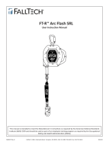
DESCRIPTION:
Figure 2 identifi es key components of the DBI-SALA Ultra-Lok Self-Retracting Devices (SRDs). Ultra-Lok SRDs are drum wound
Wire Rope Lifelines (A) which retract into a thermoplastic or aluminum Housing (B). They can hang from anchorage by a
Carabiner attached through the Swivel Eye (C) on the top of the SRD. A Self-Locking Snap Hook (D) on the end of the Lifeline
attaches to the designated Fall Arrest connection on a Full Body Harness. A Bumper (E), protects the Wire Rope and Ferrules
securing the Snap Hook from abrasion and corrosion.
Figure 1 defi nes the Ultra-Lok SRD models covered by this instruction manual. The following SRD Types are available:
• Self-Retracting Lanyard (Figure 2A): Self-Retracting Lanyards (SRLs) are suitable for applications where the lifeline
remains generally vertical during use and possible Free Fall is limited to 2 ft (0.6 m).
• Self-Retracting Lanyard with Leading Edge (Figure 2B): Self-Retracting Lanyards with Leading Edge (SRL-LEs) are
suitable for applications where the lifeline remains generally horizontally during use and possible Free Fall is limited to 5 ft
(1.5 m). SRL-LEs have an integral Energy Absorber (F), or similar component, to withstand impact loading of the lifeline
over a sharp or abrasive edge during fall arrest and minimize fall arrest forces on the user.
• Self-Retracting Lanyard with Rescue (Figure 2C): Self-Retracting Lanyards with Rescue (SRL-Rs) include an integral
means for assisted rescue by raising or lowering the rescue subject. SRL-Rs are equipped with a 3-Way Emergency
Retrieval Hand Crank (G). Some models include a Tripod Mounting Bracket (H) to mount the SRL-R on the leg of a Tripod for
Confi ned Space applications.
Table 1 – Specifi cations
Casing Halves Material
9508320 + 9511040 Aluminum - 50 ft (15 m) SRDs
9511070 + 9511071 Thermoplastic - 20 ft (6 m) and 33 ft (10 m) SRDs
9520021 + 9520022 Aluminum - 20 ft (6m) and 33 ft (10 m) SRDs
9520044 + 9520045 Thermoplastic - 50 ft (15m) and 33 ft (10 m) Leading Edge SRDs
9520046 + 9520047 Aluminum - 50 ft (15 m) SRDs
9520056 + 9520057 Thermoplastic - 66 ft (20 m), 85 ft (26 m), 100 ft (30 m), and 50 ft (15 m) Leading Edge SRDs
9520058 + 9520059 Aluminum - 66 ft (20 m), 85 ft (26 m), and 100 ft (30 m) SRDs
Lifeline Description Hook
9501087 + 2000178 7/32 in. (5.56 mm) galvanized steel wire rope, self locking alloy steel swiveling snap hook with indicator. 2000178
9501479 + 2000175 3/16 in. (4.76 mm) galvanized steel wire rope, self locking alloy steel swiveling snap hook with indicator. 2000175
9501613 + 2000175 3/16 in. (4.76 mm) stainless steel wire rope, self locking alloy steel swiveling snap hook with indicator. 2000175
9501613 + 2100044 3/16 in. (4.76 mm) stainless steel wire rope, self locking stainless steel swiveling snap hook with indicator. 2100044
Hook Description Material Gate Strength Throat Size
2000175 Swiveling Self-Locking Snap Hook with Impact Indicator Zinc Plated Steel 3,600 lbs (16 kN) .75 in (1.9 cm)
2000178 Swiveling Self-Locking Snap Hook with Impact Indicator Zinc Plated Steel 3,600 lbs (16 kN) .75 in (1.9 cm)
2100044 Swiveling Self-Locking Snap Hook with Impact Indicator Stainless Steel 3,600 lbs (16 kN) .75 in (1.9 cm)
Wire Rope Lifeline Tensile Strength: 9501479 - 3/16 in. dia. Galvanized Steel - Min. Tensile Strength 4,200 lbs (18.7 kN)
9501613 - 3/16 in. dia. Stainless Steel - Min. Tensile Strength 3,600 lbs (16.0 kN)
9501087 - 7/32 in. dia. Galvanized Steel - Min. Tensile Strength 5,600 lbs (24.9 kN)
Maximum Arrest Force: 1,350 lbs (6 kN) for 310 lbs (141 kg) Capacity
1,800 lbs (8 kN) for 420 lbs (191 kg) Capacity
Average Arrest Force: 900 lbs (4 kN)
Maximum Arrest Distance: 42 in (1.1 m)

12
1.0 APPLICATIONS
1.1 PURPOSE: Self-Retracting Devices (SRDs) are designed to be a component in a personal fall arrest system (PFAS). Figure
1 illustrates SRDs covered by this instruction manual. They may be used in most situations where a combination of worker
mobility and fall protection is required (i.e. inspection work, general construction, maintenance work, oil production,
confi ned space work, etc.).
1.2 STANDARDS: Your SRD conforms to the national or regional standard(s) identifi ed on the front cover of these
instructions.
1.3 TRAINING: This equipment is intended to be used by persons trained in its correct application and use. It is the responsibility of the
user to assure they are familiar with these instructions and are trained in the correct care and use of this equipment. Users must also
be aware of the operating characteristics, application limits, and the consequences of improper use.
1.4 LIMITATIONS: Always consider the following limitations when installing or using this equipment:
• Capacity: Per ANSI Z359.14 requirements, SRDs are for use by one person with a combined weight (clothing, tools,
etc.) from 130 lbs (59 kg) to 310 lbs (141 kg).
1
Make sure all of the components in your system are rated to a
capacity appropriate to your application.
• Anchorage: Anchorages selected for fall arrest systems shall have a strength capable of sustaining static loads
applied in the directions permitted by the system of at least:
1. 5,000 lbs. (22.2 kN) for non-certified anchorages, or
2. Two times the maximum arresting force for certified anchorages.
When more than one fall arrest system is attached to an anchorage, the strengths set forth in (1) and
(2) above shall be multiplied by the number of systems attached to the anchorage.
FROM OSHA 1926.500 AND 1910.66: Anchorages used for attachment of personal fall arrest systems shall be
independent of any anchorage being used to support or suspend platforms, and capable of supporting at least 5,000 lbs.
per user attached, or be designed, installed, and used as part of a complete personal fall arrest systems which maintains
a safety factor of at least two, and is under the supervision of a qualifi ed person.
• Locking Speed: Situations which do not allow for an unobstructed fall path should be avoided. Working in confined
or cramped spaces may not allow the body to reach sufficient speed to cause the SRD to lock if a fall occurs. Working
on slowly shifting material, such as sand or grain,may not allow enough speed buildup to cause the SRD to lock. A
clear path is required to assure positive locking of the SRD.
• Free Fall: When used correctly, SRDs will limit the free fall distance to 2 ft. (61 cm). To avoid increased fall distances,
do not work above the anchorage level. Do not lengthen SRDs by connecting a lanyard or similar component
without consulting 3M. Never clamp, knot, or prevent the lifeline from retracting or being taut. Avoid slack line.
• Swing Falls: Swing Falls occur when the anchorage point is not directly above the point where a fall occurs. The
force of striking an object in a swing fall may cause serious injury (see Figure 3A). Minimize swing falls by working as
directly below the anchorage point as possible.
• Fall Clearance: Figures 3B and 3C illustrate Fall Clearance. SRD Fall Arrest Systems should have a minimum Fall Clearance
of 6 ft (2 m) for falls from a standing position where the SRD is anchored directly overhead (Figure 3B). Falls from a
kneeling or crouching position will require an additional 3 ft (1 m) of Fall Clearance. In swing fall situations (Figure
3C), the total vertical fall distance will be greater than if the user had fallen directly below the anchorage point and
requires additional Fall Clearance. Figure 4 and the accompanying table defi ne the Maximum Work Radius (C) for
various SRD Anchorage Heights (A) and Fall Clearances (B). The Recommended Work Zone is limited to the area
located within the Maximum Work Radius.
• Hazards: Use of this equipment in areas where surrounding hazards exist may require additional precautions to reduce the
possibility of injury to the user or damage to the equipment. Hazards may include, but are not limited to: high heat, caustic
chemicals, corrosive environments, high voltage power lines, explosive or toxic gases, moving machinery, or overhead materials
that may fall and contact the user or fall arrest system. Avoid working where your lifeline may cross or tangle with that of another
worker. Avoid working where an object may fall and strike the lifeline; resulting in loss of balance or damage to the lifeline. Do not
allow the lifeline to pass under arms or between legs.
• Sharp Edges: Avoid working where the lifeline will be in contact with or abrade against unprotected sharp edges.
Where contact with a sharp edge is unavoidable, cover the edge with a protective material.
1 Capacity: 130 lbs -310 lbs (59 kg- 141 kg) is the capacity range required by standard ANSI Z359.14 Class B. Some SRDs also support a 420 lbs (191 kg)
Maximum Capacity per OSHA. See Figure 1 for the SRD models covered by this instruction and their Maximum Capacities.

13
2.0 Use
2.1 FALL PROTECTION AND RESCUE PLAN: The employer must have a Fall Protection and Rescue Plan in place that meets
ANSI Z359.2 Minimum Requirements for a Comprehensive Managed Fall Protection Program. The plan should provide
guidelines and requirements for an employer’s managed fall protection program, including policies, duties and training;
fall protection procedures; eliminating and controlling fall hazards; rescue procedures; incident investigations; and
evaluating program effectiveness.
2.2 INSPECTION FREQUENCY:
SRDs shall be inspected by the authorized person
1
or rescuer
2
before each use (See Table
2). Additionally, inspections shall be conducted by a competent person
3
other than the user. Extreme working conditions
(harsh environment, prolonged use, etc.) may necessitate more frequent competent person inspections. The competent
person shall use the Inspection Schedule (Table 1) to determine appropriate inspection intervals.
Inspection procedures
are described in the Inspection & Maintenance Log (Table 2). Results of the Competent Person inspection should be recorded
in the Inspection and Maintenance Log or recorded with the i-Safe™ system (see Section 5).
2.3 NORMAL OPERATIONS: Normal operation will allow the lifeline to extend and retract with no hesitation or slack as
the worker moves at normal speeds. If a fall occurs, a speed sensing brake system will activate, stopping the fall and
absorbing much of the energy created. Sudden or quick movements should be avoided during normal work operation, as
this may cause the SRD to lock up. For falls which occur near the end of the lifeline travel, a reserve lifeline system or
Energy Absorber has been incorporated to reduce the fall arrest forces.
2.4 BODY SUPPORT: A Full Body Harness must be used with the Self-Retracting Device. The harness connection point must be
above the user’s center of gravity. A body belt is not authorized for use with the Self-Retracting Device. If a fall occurs when
using a body belt it may cause unintentional release or physical trauma from improper body support.
2.5 COMPATIBILITY OF COMPONENTS: Unless otherwise noted, 3M equipment is designed for use with 3M approved
components and subsystems only. Substitutions or replacements made with non approved components or subsystems may
jeopardize compatibility of equipment and may affect safety and reliability of the complete system.
2.6 COMPATIBILITY OF CONNECTORS: Connectors are considered to be compatible with connecting elements when they
have been designed to work together in such a way that their sizes and shapes do not cause their gate mechanisms to
inadvertently open regardless of how they become oriented. Contact 3M if you have any questions about compatibility.
Connectors (hooks, carabiners, and D-rings) must be capable of supporting at least 5,000 lbs. (22.2 kN). Connectors
must be compatible with the anchorage or other system components. Do not use equipment that is not compatible.
Non-compatible connectors may unintentionally disengage (see Figure 5). Connectors must be compatible in size, shape,
and strength. Self-locking snap hooks and carabiners are required. If the connecting element to which a snap hook or
carabiner attaches is undersized or irregular in shape, a situation could occur where the connecting element applies a
force to the gate of the snap hook or carabiner (A). This force may cause the gate to open (B), allowing the snap hook or
carabiner to disengage from the connecting point (C).
2.7 MAKING CONNECTIONS: Snap hooks and carabiners used with this equipment must be self-locking. Ensure all
connections are compatible in size, shape and strength. Do not use equipment that is not compatible. Ensure all
connectors are fully closed and locked. 3M connectors (snap hooks and carabiners) are designed to be used only as
specifi ed in each product’s user’s instructions. See Figure 6 for examples of inappropriate connections. Do not connect
snap hooks and carabiners:
A. To a D-ring to which another connector is attached.
B. In a manner that would result in a load on the gate. Large throat snap hooks should not be connected to standard
size D-rings or similar objects which will result in a load on the gate if the hook or D-ring twists or rotates, unless the
snap hook is equipped with a 3,600 lb (16 kN) gate.
C. In a false engagement, where size or shape of the mating connectors are not compatible and, without visual
confi rmation, the connectors seem fully engaged.
D. To each other.
E. Directly to webbing or rope lanyard or tie-back (unless the manufacturer’s instructions for both the lanyard and
connector specifi cally allows such a connection).
F. To any object which is shaped or dimensioned such that the snap hook or carabiner will not close and lock, or that
roll-out could occur.
G. In a manner that does not allow the connector to align properly while under load.
Table 1 – Inspection Schedule
Type of Use Application Examples Conditions of Use
Inspection Frequency
Competent Person
Infrequent to Light Rescue and Confi ned Space,
Factory Maintenance
Good Storage Conditions, Indoor or Infrequent
Outdoor Use, Room Temperature, Clean Environments
Annually
Moderate to Heavy Transportation, Residential
Construction, Utilities, Warehouse
Fair Storage Conditions, Indoor and Extended Outdoor
Use, All Temperatures, Clean or Dusty Environments
Semi-Annually to
Annually
Sever to Continuous Commercial Construction, Oil and
Gas, Mining
Harsh Storage Conditions, Prolonged or Continuous
Outdoor Use, All Temperatures, Dirty Environment
Quarterly to Semi-
Annually
1 Authorized Person: A person assigned by the employer to perform duties at a location where the person will be exposed to a fall hazard.
2 Rescuer: Person or persons other than the rescue subject acting to perform an assisted rescue by operation of a rescue system.
3 Competent Person: An individual designated by the employer to be responsible for the immediate supervision, implementation, and monitoring of the
employer’s managed fall protection program who, through training and knowledge, is capable of identifying, evaluating, and addressing existing and potential fall
hazards, and who has the employer’s authority to take prompt corrective action with regard to such hazards.

14
2.8 SELF-RETRACTING LANYARDS WITH LEADING EDGE (SRL-LE): The SRDs covered by this instruction manual in-
clude Self-Retracting Lanyards with Leading Edge capabilities (SRL-LEs). See Figure 1 for specifi c SRL-LE models. SRL-LEs
were tested for horizontal use and falls over a steel edge without burrs. SRL-LEs may be used in situations where a fall
may occur over steel edges, such as found on steel shapes or metal sheeting.
Leading Edge Precautions: Observe the following precautions when using SRL-LEs:
• The allowable angle of redirection of the lifeline portion of the SRL-LE at the edge over which a fall might occur
(measured between the two sides formed by the redirected lifeline) shall be at least 90 degrees (see Figure 7).
• The anchor point shall be situated at the same height as the edge at which a fall might occur or above the edge.
Anchor points below the edge are dangerous because they cause the lifeline to redirect at an angle sharper than 90
degrees (see Figure 7).
• Consult Section 1 for limitations to the allowable work area relative to the anchorage point, including factors such
as swing fall and abrasion on the line at the edge and the use of a single anchor point versus anchors that allow
horizontal movement (e.g., Horizontal Lifeline or Horizontal Rail).
• SRL-LEs may be used with a Horizontal Lifeline or Horizontal Rail only as instructed in the product instructions for the
Horizontal Lifeline or Horizontal Rail.
• Do not work on the far side of an opening opposite the SRL-LE anchorage point.
• In the event of a fall over the edge, special rescue measures may be required.
• When planning your Leading Edge application, be sure work area parameters are within the Minimum Setback
Distance, Maximum Free Fall Distance, and Minimum Fall Clearance Required when Falling Over an Edge as indicated
on the SRL-LE labeling.
Leading Edge Fall Clearance Calculation: The Minimum Fall Clearance Required when Falling Over an Edge can be
calculated based on the Setback Distance and Distance Along the Edge of your Leading Edge application (see Figure 8). To
calculate Fall Clearance from the table in Figure 8:
1. Select the value closest to your Setback Distance (A) in the left-side row headings.
2. Select the value closest to your working Distance Along the Edge (B) from the top column headings. Shaded areas
with no values indicate the Distance Along the Edge is outside of the safe Work Radius for your selected Setback
Distance.
3. The Clearance Required when Falling Over an Edge (C) will be the value listed at the intersection of the row selected
in Step 1 and the column selected in Step 2.
Repeat the previous steps for every edge over which the worker could potentially fall to determine safe placement of
anchorage and allowable Work Radius.

15
3.0 Installation
3.1 PLANNING: Plan your fall protection system before starting your work. Account for all factors that may affect your safety
before, during, and after a fall. Consider all requirements and limitations defi ned in this manual.
3.2 ANCHORAGE: Figure 9 illustrates typical SRL anchorage connections. The anchorage (A) should be directly overhead to
minimize Free Fall and Swing Fall hazards (see Section 2). Select a rigid anchorage point capable of sustaining the static
loads defi ned in Section 2.2. The Swivel Eye on the SRL is equipped with a Carabiner (B). Attach the Carabner directly to
the anchorage structure (rebar, angle iron, etc.), a Tie-Off Adaptor (C), or Anchorage Connection Point (D).
3.3 HARNESS CONNECTION: A Full Body Harness is required for Fall Arrest applications. Connect the Snap Hook (A) on
the SRL Lifeline to the Back Dorsal D-Ring (B) on the Full Body Harness. (see Figure 10). For situations such as ladder
climbing, it may be useful to connect to the front Sternal D-Ring. Consult the harness manufacturer’s instructions for
details regarding use of the harness connection points.
3.4 TRIPOD MOUNTING: Figure 11 illustrates installation of the Ultra-Lok Self-Retracting Device with Retrieval Hand-Crank
on a DBI-SALA Tripod. The SRL-R is mounted on a leg of the Tripod and the Lifeline is routed through a Pulley System on
the Head of the Tripod. See the instructions included with your Tripod and Mounting Bracket for details.
4.0 OPERATION
;
First time or infrequent users of Ultra-Lok Self-Retracting Devices (SRDs) should review the “Safety Information” at
the beginning of this manual prior to use of the SRD.
4.1 BEFORE EACH USE: Before each use of this fall protection equipment carefully inspect it to assure it is in good working
condition. Check for worn or damaged parts. Ensure all bolts are present and secure. Check that the lifeline is retracting
properly by pulling out the line and allowing it to slowly retract. If there is any hesitation in retraction the unit should be
marked as “UNUSABLE” and returned to an authorized service center for service. Inspect the lifeline for cuts, frays, burns,
crushing and corrosion. Check locking action by pulling sharply on the line. See Section 5 for inspection details. Do not use if
inspection reveals an unsafe condition.
4.2 AFTER A FALL: Any equipment which has been subjected to the forces of arresting a fall or exhibits damage consistent
with the effect of fall arrest forces as described in Section 5, must be removed from service immediately, marked as
“UNUSABLE”, and inspected and serviced as instructed in Sections 5 and 6.
4.3 BODY SUPPORT: A full body harness must be worn when using 3M SRLs. For general fall protection use, connect to
the back Dorsal D-Ring. For situations such as ladder climbing, it may be useful to connect to the front Sternal D-Ring.
Consult the harness manufacturer’s instructions for details regarding use of the harness connection points.
4.4 MAKING CONNECTIONS: When using a hook to make a connection, ensure roll-out cannot occur (see Figure 5). Do not
use hooks or connectors that will not completely close over the attachment object. Do not use non-locking snap hooks.
The mounting surface should meet the anchorage strength requirements stated in section 2.2. Follow the manufacturer’s
instructions supplied with each system component.
4.5 OPERATION: Inspect the SRL as described in section 5.0. Connect the SRL to a suitable anchorage or anchorage
connector as previously described. Connect the Self-Locking Snap Hook on the end of the lifeline to the Dorsal D-Ring on
the Full Body Harness (see Figure 10). Ensure connections are compatible in size, shape, and strength. Ensure hook is
fully closed and locked. Once attached, the worker is free to move about within the recommended working area at normal
speeds. If the RSQ Selection Knob is set to ‘Fall Arrest’, the SRL will arrest the fall. If the RSQ Selection Knob is set to
‘Descent’, the SRL will automatically descend the user to a lower level when a fall occurs. When working with an SRL,
always allow the lifeline to recoil back into the device under control. A tag line may be required to extend or retract the
lifeline during connection and disconnection operations. A tag line can be used to prevent uncontrolled retraction of the
lifeline into the SRL. Depending on the work site environment and conditions, it may be necessary to restrain the free end
of the tag line to prevent interference and entanglement with equipment or machinery.
4.6 RETRIEVAL OPERATION: Figure 12 illustrates operation of the Integral Rescue Hand Crank on the Ultra-Lok Retrieval
SRL-R. Do not attempt to operate Retrieval with the lifeline fully retracted. To activate Retrieval mode and use the Rescue
Hand Crank:
1. Pull out on the Retrieval Handle to release the Crank Arm.
2. Rotate the Retrieval Handle out from the SRL Body 180°.
3. Pull and hold the Shift Knob in the unlocked position.
4. Push the Crank Arm in and release the Shift Knob to engage. If needed, rotate the Crank Arm clockwise to help
engage the gear.
5. Raise and lower the Lifeline as illustrated in Figure 12:
A. To Raise: Rotate the Crank Arm counterclockwise.
B. To Lower: Crank the Crank Arm counterclockwise slightly to release the Fall Arrest Brake, then crank the Crank
Arm Clockwise..
;
The Integral Rescue Hand Crank on 3-Way Emergency Retrieval SRL-R models is for rescue purposes only and
should not be used for work positioning or material lifting/lowering.

16
;
Ultra-Lok SRL-Rs do not incorporate an Overload Clutch to limit the force exerted on the drive components and
attached person. Avoid line slack while in Retrieval mode. Also, monitor the individual during retrieval to ensure they
are not subjected to excessive force from continued lifting after entanglement on an obstruction.
;
A minimum load of 75 lbs (33.9 kg) is required to lower or pay out the Lifeline. A force of 30 lbs (0.13 kN) is
required to operate the Retrieval system when loaded to capacity.
;
Stop cranking when the Lifeline is fully extended or retracted. Continued cranking can damage components.
4.7 RETRIEVAL DISENGAGEMENT: To disengage Retrieval mode:
;
When Retrieval mode is disengaged, any extended Lifeline will retract into the SRL. To avoid possible injury, retract
the Lifeline prior to disengagement or hold onto the Lifeline.
1. Remove any load from the Lifeline.
2. Pull and hold the Shift Knob in the unlocked position.
3. Pull the Crank Arm out to disengage and then release the Shift Knob.
4. Pull out and rotate the Retrieval Handle 180° toward the SRL Body to stowed position.
5.0 Inspection
5.1 INSPECTION FREQUENCY: The Ultra-Lok Self-Retracting Device must be inspected at the intervals defi ned in
Section 2.2 - Inspection Frequency”. Inspection procedures are described in the “Inspection Checklist” (Table 2).
;
Extreme working conditions (harsh environments, prolonged use, etc.) may require increasing the frequency of
inspections.
5.2 UNSAFE OR DEFECTIVE CONDITIONS: If inspection reveals an unsafe defective condition, remove the
Self-Retracting Device from service immediately, mark as “UNUSABLE”, and send to an authorized service center for
repair.
;
Only 3M or parties authorized in writing may make repairs to this equipment.
5.3 PRODUCT LIFE: The functional life of 3M Self-Retracting Devices is determined by work conditions and maintenance. As
long as the product passes inspection criteria, it may remain in service.
6.0 MAINTENANCE, SERVICE, and STORAGE
6.1 CLEANING: Cleaning procedures for the Self-Retracting Device are as follows:
• Periodically clean the exterior of the SRL using water and a mild soap solution. Position the SRD so excess water can
drain out. Clean labels as required.
• Clean lifeline with water and mild soap solution. Rinse and thoroughly air dry. Do not force dry with heat. An
excessive buildup of dirt, paint, etc. may prevent the lifeline from fully retracting back into the housing causing a
potential free fall hazard. Replace lifeline if excessive buildup is present.
6.2 SERVICE: Additional maintenance and servicing procedures must be completed by an authorized service center. Do not
attempt to disassemble the SRL or lubricate any parts.
6.3 STORAGE AND TRANSPORT: Store and transport Self-Retracting Device in a cool, dry, clean environment out of direct
sunlight. Avoid areas where chemical vapors may exist. Thoroughly inspect the SRL after any period of extended storage.
7.0 Labels
Figure 19 illustrates labels on the the Ultra-Lok Self-Retracting Devices and their locations. All labels must be present on the
SRD. Labels must be replaced if they are not fully legible.

17
Table 2 – Inspection Checklist
Serial Number(s): Date Purchased:
Model Number: Date of First Use:
Inspected By: Inspection Date:
Component: Inspection:
Before
Each Use
Competent
Person
SRL
(Figure 13)
Inspect for loose bolts and bent or damaged parts.
Inspect Housing (A) for distortion, cracks, or other damage.
Inspect the Swivel Eye (B) for distortion, cracks, or other damage. The Swivel Eye should be attached
securely to the SRL, but should pivot freely.
The Lifeline (C) should pull out and retract fully without hesitation or creating a slack line condition.
Ensure device locks up when lifeline is jerked sharply. Lockup should be positive with no slipping.
The labels must be present and fully legible (see Figure 19).
Look for signs of corrosion on the entire unit.
Swivel Snap Hook & Impact
Indicator
(Figure 14
Inspect the Swivel Snap Hook for signs of damage, corrosion, and working condition. Swivel should
rotate freely. Inspect the Impact Indicator. If the Red Band is displayed (Indicated Mode), impact
loading has occurred and the SRL must be removed from service and inspected. Do not attempt to
reset the Impact Indicator. Return the SRL to an authorized service center for resetting. NOTE: The
Swivel will not turn freely when the Impact Indicator is in Indicated Mode.
Wire Rope Lifeline
(Figure 15)
Inspect wire rope for cuts, kinks (A), broken wires (B), bird-caging (C), welding splatter, (D) corrosion,
chemical contact areas, or severely abraded areas. Slide the cable bumper (E) up and inspect ferrules
(F) for cracks or damage and inspect the wire rope for corrosion and broken wires. Replace the wire
rope assembly if there are six or more randomly distributed broken wires in one lay, or three or more
broken wires in one strand in one lay. A “lay” of wire rope is the length of wire rope it takes for a
strand (the larger groups of wires) to complete one revolution or twist along the rope. Replace the
wire rope assembly if there are any broken wires within 1 inch (25 mm) of the ferrules.
Reserve Lifeline
(Figure 16)
Inspect the reserve lifeline payout. If a fall has been arrested with most of the lifeline out, the reserve
lifeline may have been deployed. Pull the lifeline out of the SRL until it stops. If a red band (G) is
visible, the reserve lifeline is spent and the unit must be serviced by an authorized service center
before reuse.
SRL-LE Energy Absorber
(Figure 17)
On Self-Retracting Lanyards with Leading Edge capability (SRL-LEs) verify that the integral Energy
Absorber has not been activated. There should be no webbing pulled out of the cover (A). The cover
should be secure and free of tears (B) or other damage.
Retrieval Integral Rescue Hand
Crank
(Figure 18)
Inspect the Crank Arm (A) for distortion or other damage. Ensure that the Retrieval Handle (B) can be
folded out and secured in the cranking position.
Ensure the Retrieval Shift Knob (C) can be pulled out to the unlocked position and then released,
locking the Crank Arm in both the engaged and disengaged positions.
Test the retrieval feature for proper operation by raising and lowering a test weight of at least 75 lbs
(34 kg). When the Retrieval Handle is released, the weight should not move and the Retrieval Handle
should remain in position (no movement). A ‘clicking’ sound should be audible when raising the load.
Corrective Action/Maintenance: Approved By:
Date:
Corrective Action/Maintenance: Approved By:
Date:
Corrective Action/Maintenance: Approved By:
Date:
Corrective Action/Maintenance: Approved By:
Date:
Corrective Action/Maintenance: Approved By:
Date:
Corrective Action/Maintenance: Approved By:
Date:
Corrective Action/Maintenance: Approved By:
Date:
Corrective Action/Maintenance: Approved By:
Date:
Corrective Action/Maintenance: Approved By:
Date:
Corrective Action/Maintenance: Approved By:
Date:
Corrective Action/Maintenance: Approved By:
Date:


LIMITED LIFETIME WARRANTY
Warranty to End User: D B Industries, LLC dba CAPITAL SAFETY USA (“CAPITAL SAFETY”)
warrants to the original end user (“End User”) that its products are free from defects in materials and
workmanship under normal use and service. This warranty extends for the lifetime of the product
from the date the product is purchased by the End User, in new and unused condition, from a CAPITAL
SAFETY authorized distributor. CAPITAL SAFETY’S entire liability to End User and End User’s exclusive
remedy under this warranty is limited to the repair or replacement in kind of any defective product
within its lifetime (as CAPITAL SAFETY in its sole discretion determines and deems appropriate). No oral
or written information or advice given by CAPITAL SAFETY, its distributors, directors, offi cers, agents
or employees shall create any diff erent or additional warranties or in any way increase the scope of
this warranty. CAPITAL SAFETY will not accept liability for defects that are the result of product abuse,
misuse, alteration or modifi cation, or for defects that are due to a failure to install, maintain, or use the
product in accordance with the manufacturer’s instructions.
CAPITAL SAFETY’S WARRANTY APPLIES ONLY TO THE END USER. THIS WARRANTY IS THE ONLY
WARRANTY APPLICABLE TO OUR PRODUCTS AND IS IN LIEU OF ALL OTHER WARRANTIES AND
LIABILITIES, EXPRESSED OR IMPLIED. CAPITAL SAFETY EXPRESSLY EXCLUDES AND DISCLAIMS
ANY IMPLIED WARRANTIES OF MERCHANTABILITY OR FITNESS FOR A PARTICULAR PURPOSE, AND
SHALL NOT BE LIABLE FOR INCIDENTAL, PUNITIVE OR CONSEQUENTIAL DAMAGES OF ANY NATURE,
INCLUDING WITHOUT LIMITATION, LOST PROFITS, REVENUES, OR PRODUCTIVITY, OR FOR BODILY
INJURY OR DEATH OR LOSS OR DAMAGE TO PROPERTY, UNDER ANY THEORY OF LIABILITY, INCLUDING
WITHOUT LIMITATION, CONTRACT, WARRANTY, STRICT LIABILITY, TORT (INCLUDING NEGLIGENCE) OR
OTHER LEGAL OR EQUITABLE THEORY.
GARANTÍA LIMITADA DE POR VIDA
Garantía para el usuario fi nal: D B Industries, LLC, que opera bajo el nombre de CAPITAL SAFETY USA
(“CAPITAL SAFETY”) garantiza al usuario fi nal original (“Usuario fi nal”) que sus productos están libres de defectos
de materiales y de mano de obra en condiciones normales de uso y mantenimiento. Esta garantía se extiende
durante la vida útil del producto a partir de la fecha en que el Usuario fi nal adquiere el producto, nuevo y sin
uso, a un distribuidor autorizado de CAPITAL SAFETY. La entera responsabilidad de CAPITAL SAFETY hacia el
Usuario fi nal y el remedio exclusivo para el Usuario fi nal bajo esta garantía están limitados a la reparación o el
reemplazo por materiales de todo producto defectuoso dentro de su vida útil (según CAPITAL SAFETY lo determine
y considere apropiado a su solo criterio). Ninguna información o asesoramiento, oral o escrito, proporcionado
por CAPITAL SAFETY, sus distribuidores, directores, funcionarios, agentes o empleados creará una garantía
diferente o adicional ni aumentará de ninguna manera el alcance de esta garantía. CAPITAL SAFETY no aceptará
responsabilidad por defectos resultantes del abuso, el uso incorrecto, la alteración o la modifi cación del producto,
ni por defectos resultantes de no respetar las instrucciones del fabricante durante la instalación, el mantenimiento
o el uso del producto.
LA GARANTÍA DE CAPITAL SAFETY SE APLICA ÚNICAMENTE AL USUARIO FINAL. ESTA GARANTÍA ES LA
ÚNICA GARANTÍA QUE SE APLICA A NUESTROS PRODUCTOS Y REEMPLAZA A TODAS LAS OTRAS GARANTÍAS
Y RESPONSABILIDADES, EXPRESAS O IMPLÍCITAS. CAPITAL SAFETY EXPRESAMENTE EXCLUYE Y RENUNCIA A
TODAS LAS GARANTÍAS IMPLÍCITAS DE COMERCIABILIDAD O APTITUD PARA UN PROPÓSITO PARTICULAR, Y
NO SERÁ RESPONSABLE POR DAÑOS INCIDENTALES, PUNITIVOS O EMERGENTES DE NINGUNA NATURALEZA,
INCLUYENDO SIN LIMITACIÓN PÉRDIDAS DE INGRESOS, GANANCIAS O PRODUCTIVIDAD; NI POR
LESIONES CORPORALES O MUERTE, O PÉRDIDA DE O DAÑO A LA PROPIEDAD, BAJO CUALQUIER TEORÍA DE
RESPONSABILIDAD, INCLUYENDO SIN LIMITACIÓN CONTRATO, GARANTÍA, RESPONSABILIDAD ESTRICTA,
AGRAVIO (INCLUIDA NEGLIGENCIA) O CUALQUIER OTRA TEORÍA LEGAL O EQUITATIVA.

ISO
9001
USA
3833 SALA Way
Red Wing, MN 55066-5005
Toll Free: 800.328.6146
Phone: 651.388.8282
Fax: 651.388.5065
solutions@capitalsafety.com
Brazil
Rua Anne Frank, 2621
Boqueirão Curitiba PR
81650-020
Brazil
Phone: 0800-942-2300
brasil@capitalsafety.com
Mexico
Calle Norte 35, 895-E
Col. Industrial Vallejo
C.P. 02300 Azcapotzalco
Mexico D.F.
Phone: (55) 57194820
mexico@capitalsafety.com
Colombia
Compañía Latinoamericana de Seguridad S.A.S.
Carrera 106 #15-25 Interior 105 Manzana 15
Zona Franca - Bogotá, Colombia
Phone: 57 1 6014777
servicioalcliente@capitalsafety.com
Canada
260 Export Boulevard
Mississauga, ON L5S 1Y9
Phone: 905.795.9333
Toll-Free: 800.387.7484
Fax: 888.387.7484
info.ca@capitalsafety.com
EMEA (Europe, Middle East, Africa)
EMEA Headquarters:
5a Merse Road
North Moons Moat
Redditch, Worcestershire
B98 9HL UK
Phone: + 44 (0)1527 548 000
Fax: + 44 (0)1527 591 000
csgne@capitalsafety.com
France:
Le Broc Center
Z.I. 1re Avenue - BP15
06511 Carros Le Broc Cedex
France
Phone: + 33 04 97 10 00 10
Fax: + 33 04 93 08 79 70
information@capitalsafety.com
Australia & New Zealand
95 Derby Street
Silverwater
Sydney NSW 2128
Australia
Phone: +(61) 2 8753 7600
Toll-Free : 1800 245 002 (AUS)
Toll-Free : 0800 212 505 (NZ)
Fax: +(61) 2 8753 7603
sales@capitalsafety.com.au
Asia
Singapore:
69, Ubi Road 1, #05-20
Oxley Bizhub
Singapore 408731
Phone: +65 - 65587758
Fax: +65 - 65587058
inquiry@capitalsafety.com
Shanghai:
Rm 1406, China Venturetech Plaza
819 Nan Jing Xi Rd,
Shanghai 200041, P R China
Phone: +86 21 62539050
Fax: +86 21 62539060
inquiry@capitalsafety.cn
www.capitalsafety.com
-
 1
1
-
 2
2
-
 3
3
-
 4
4
-
 5
5
-
 6
6
-
 7
7
-
 8
8
-
 9
9
-
 10
10
-
 11
11
-
 12
12
-
 13
13
-
 14
14
-
 15
15
-
 16
16
-
 17
17
-
 18
18
-
 19
19
-
 20
20


3M PROTECTA® Self Retracting Lifeline - Retrieval 3591000, Red, 50 ft. (15.2 m) Operating instructions
- Type
- Operating instructions
Ask a question and I''ll find the answer in the document
Finding information in a document is now easier with AI
Related papers
-
DBI-SALA DBI-SALA® Nano-Lok™ Twin-Leg Quick Connect Self Retracting Lifeline, Web 3101278 Operating instructions
-
DBI-SALA DBI-SALA® Twin-Leg Tie-Back Quick Connect Self Retracting Lifeline, Web 3102115, 7.5 ft. (2.3m), 1 EA User manual
-
3M DBI-SALA® Nano-Lok™ Wrap Back Self-Retracting Lifeline, Web 3101658, Blue, 8 ft. (2.4m), 1 EA Operating instructions
-
-
DBI-SALA DBI-SALA® Cab Mount Self Retracting Lifeline, Web 3101008, 8 ft. (2.4m), 1 EA User manual
-
-
-
-
3M DBI-SALA® Nano-Lok™ Extended Length Self Retracting Lifeline 3103866, 20ft Web, 1 ea Operating instructions
-
Other documents
-
Honeywell Miller MightEvac User Instruction Manual
-
PROTECTA 3590680 User manual
-
Guardian Fall Protection 10901 User manual
-
 DBI/Sala Water Dispenser 2100090 User manual
-
Werner C111506 User manual
-
Checkmate FABX SRL-LE User manual
-
 FallTech 727650LE User guide
-
Guardian Quadro (formerly Big Boss) Horizontal Lifeline Operating instructions
-
 FallTech 721530TD1 User manual
-
Werner Full Body Harness Operating instructions


