Page is loading ...

P/N: 1802002051025
*1802002051025*
EDS-G205A-4PoE
Quick Installation Guide
Moxa EtherDevice Switch
Edition 4.1, June 2017
Technical Support Contact Information
www.moxa.com/support
Moxa Americas:
Toll
-free: 1-888-669-2872
Tel:
1-714-528-6777
Fax:
1-714-528-6778
Moxa China (Shanghai office):
Toll
-free: 800-820-5036
Tel:
+86-21-5258-9955
Fax:
+86-21-5258-5505
Moxa Europe:
Tel:
+49-89-3 70 03 99-0
Fax:
+49-89-3 70 03 99-99
Moxa Asia-Pacific:
Tel:
+886-2-8919-1230
Fax:
+886-2-8919-1231
Moxa India:
Tel:
+91-80-4172-9088
Fax:
+91-80-4132-1045
2017 Moxa Inc. All rights reserved.

- 2 -
Overview
The EDS-G205A-4PoE series industrial Ethernet switches are rugged
entry-level industrial 5-port Gigabit PoE switches for environments that
fall under the pollution degree 2 category. The industrial Ethernet
switches support IEEE 802.3, IEEE 802.3u, and IEEE 802.3x with
10/100/1000M, full/half-duplex, MDI/MDIX auto-sensing, and IEEE
802.3af/IEEE 802.3at PoE standards.
The EDS-G205A-4PoE series provides 12/24/48 VDC redundant power
inputs that can be connected simultaneously to a live DC power source.
The switches are available with a standard operating temperature range
from 0 to 60°C, or with a wide operating temperature range from -40 to
75°C, and their IP30 metal housing makes them rugged enough for any
harsh industrial environment.
To provide greater versatility for use with applications from different
industries, the EDS-G205A-4PoE switches also allow users to enable or
disable broadcast storm protection, 802.3az, Jumbo frame, and PoE high
power with DIP switches on the outer panel. The EDS-G205A-4PoE
switches can be easily installed on a DIN-Rail or in distribution boxes. The
DIN-Rail mounting capability and IP30 metal housing with LED indicators
make the plug-and-play EDS-G205A-4PoE switches reliable and easy to
use.
NOTE
Throughout this Hardware Installation Guide, we use EDS as an
abbreviation for Moxa EtherDevice Switch:
EDS = Moxa EtherDevice Switch
Package Checklist
Your EDS is shipped with the following items. If any of these items is
missing or damaged, please contact your customer service
representative for assistance.
• Moxa EtherDevice™ Switch
• Quick Installation Guide (printed)
• Warranty card
Features
High-watt Power-over-Ethernet
• Up to 30 watts output per PoE port (IEEE 802.3at)
• Supports PoE high power output up to 36 W
• Short circuit and over-current protection
• Auto detection for IEEE 802.3af and IEEE 802.3at
High Performance Network Switching Technology
• 10/100BaseT(X), 1000BaseT and 100/1000BaseX (SFP)
• 10/100/1000M, Full/Half-Duplex, MDI/MDIX auto-sensing
• IEEE 802.3/802.3u/802.3x
• Store and Forward switching process type, 8k MAC address entries
• 10k jumbo frames
Rugged Design
• Redundant dual 12/24/48 VDC power inputs
• Operating temperature range from 0 to 60°C, or extended operating
temperature of -40 to 75°C for (T) models.

- 3 -
• IP30 metal housing
• DIN-rail or panel mounting ability
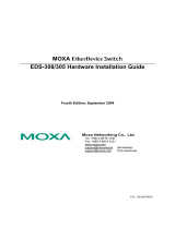
EDS-G205A-4PoE Panel Layouts
1. Terminal blocks for P1/P2
power inputs
2. Power input P1 LED
3. Power input P2 LED
4. PoE status LED
5. 10/100/1000BaseT(X) PoE
ports (ports 2, 3, 4, 5)
6. TP port speed LED
7. 10/100/1000BaseT(X) port
(port 1)
8. 100/1000BaseX SFP slot
9. Model name
10.
Grounding screw
11.
P1 power input terminal
block
12.
P2 power input terminal
block
13.
DIP switches
14.
Screw holes for panel
mounting kit
15.
DIN-rail mounting kit

- 4 -
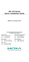
Mounting Dimensions
Unit = mm (inch)

- 5 -
DIN-Rail Mounting
The aluminum DIN-rail attachment plate should already be fixed to the
back panel of the EDS when you take it out of the box. If you need to
reattach the DIN-rail attachment plate, make sure the stiff metal spring is
situated towards the top, as shown in the figures below.
STEP 1: Insert the top of the
DIN
-rail into the slot just below
the stiff m
etal spring.
STEP 2: The DIN-Rail attachment
unit will snap into place as shown
below.
To remove the EDS from the DIN-rail, simply reverse Steps 1 and 2
above.
Wall Mounting (optional)
For some applications, you will find it convenient to mount the
EDS-G205A-4PoE on a wall, as shown in the following figures.
STEP 1:
Remove the aluminum
DIN
-rail attachment plate
from
the EDS-G205A-
4PoE’s
rear panel, and then attach
the wall mount plates as
shown
in the diagram at
the
right.
STEP 2:
Mounting
the EDS-G205A-
4PoE on the wall requires 4
screws
and the recommended tightening torque is
3.5±0.5
(kgf cm). Use the switch, with wall mount
plates attached, as a guide to mark the correct
locations of the 4 screws. The heads of the screws
should be less than 6.0 mm in diameter, and the shafts
should be less than 3.5
mm in diameter, as shown in
the figure at the right.
NOTE
Before tightening the screws into the wall, make sure the screw
head and shank size are suitable by inserting the screw into one
of the keyhole
-shaped apertures of the wall mounting plates.
Do
not screw the screws in completely—leave about 2 mm to
allow room for sliding the wall mount panel between the wall and
the screws

- 6 -
STEP 3:
Once the screws are fixed on the
wall, insert the four screw heads
through the large parts of the
keyhole
-
shaped apertures, and then
slide
the EDS downwards, as
indicated. Tighten the four screws
for
added stability.
Wiring Requirements
WARNING
Safety First
Turn the power off before disconnecting modules or wires. The
correct
power supply voltage is listed on the product label. Check
the voltage of your power source to make sure that you are using
the correct voltage. Do NOT use a voltage greater than what is
specified on the product label
Calculate the maximum possible current in each power wire and
common wire. Observe all electrical codes dictating the
maximum current allowable for each wire size. If the current goes
above the maximum ratings, the wiring could overheat, causing
serious damage to your equipment.
You should also pay attention to the following points:
• Use separate paths to route wiring for power and devices. If power
wiring and device wiring paths must cross, make sure the wires are
perpendicular at the intersection point.
NOTE: Do not run signal or communications wiring and power wiring
in the same wire conduit. To avoid interference, wires with different
signal characteristics should be routed separately.
• You can use the type of signal transmitted through a wire to
determine which wires should be kept separate. The rule of thumb is
that wiring that shares similar electrical characteristics can be
bundled together.
• Keep input wiring and output wiring separated.
• It is strongly advised that you label wiring to all devices in the system
when necessary.
• Please use copper conductor only.

- 7 -
Grounding the EtherDevice Switch
Grounding and wire routing help limit the effects of noise due to
electromagnetic interference (EMI). Run the ground connection from the
ground screw to the grounding surface prior to connecting devices.
ATTENTION
This product is intended to be mounted to a well
-grounded
mounting surface such as a metal panel.
Wiring the Redundant Power Inputs
The two 2-contact terminal block connectors on the EDS’s top panel are
used for the EDS’s two DC power inputs. Top and front views of the
terminal block connectors are shown here.
STEP 1:
Insert the negative/positive DC wires into the V
-/V+
terminals.
STEP 2:
To keep the DC wires from pulling loose, use a small
flat
-blade screwdriver to tighten the wire-
clamp screws on
the front of the terminal block connector.
STEP 3:
Insert the plastic terminal block connector prongs into the
terminal block receptor, which is located on
the
EDS’s top
panel.
ATTENTION
Before connecting the EtherDevice Switch to the DC power
inputs,
make sure the DC power source voltage is stable and
the
DC power source is supplied by UL Listed Isolated Power Supply.
Communication Connections
The EDS-G205A-4PoE switches have 4 10/100/1000Base-T(X) PoE
Ethernet ports for connecting PoE devices, and 1 10/100/1000BaseT port
or 1 100/1000BaseX SFP slot for uplink connection. For fiber connections,
a field installed optical transceiver must be UL Recognized, in the Class I
category, and contain the following CDRH Certification Marking:
‘Complies with 21CFR 1040.10 and 1040.11’.
10/100/1000BaseT(X) Ethernet Port Connection
10/100/1000BaseT(X) ports located on the EDS’s front panel are used to
connect to Ethernet-enabled devices. Below we show pinouts for both
MDI (NIC-type) ports and MDI-X (HUB/switch-type) ports, and also show
cable wiring diagrams for straight-through and cross-over Ethernet
cables.

- 8 -
10/100BaseT(x) RJ45 Pinouts
MDI Port Pinouts
MDI-X Port Pinouts
8-pin RJ45
Pin
Signal
1
Tx+
2
Tx-
3
Rx+
6
Rx-
Pin
Signal
1
Rx+
2
Rx-
3
Tx+
6
Tx-
1000BaseT RJ45 Pinouts
Pin
MDI
MDI-X
1
BI_DA+
BI_DB+
2
BI_DA-
BI_DB-
3
BI_DB+
BI_DA+
4
BI_DC+
BI_DD+
5
BI_DC-
BI_DD-
6
BI_DB-
BI_DA-
7
BI_DD+
BI_DC+
8
BI_DD-
BI_DC-
PoE Ethernet Port Connection
PoE ports located on the EDS switch’s front panel are used to connect to
PoE-enabled devices. The pinout follows the Alternative A, MDI mode of
802.3af/802.3at standards. Details are shown below.
PoE Port Pinouts
8-pin RJ45
Pin
Power
1
V+
2
V+
3
V-
6
V-
NOTE
According to IEEE 802.3af/at standards, the PD shall be
implemented to be insensitive to the polarity of the power supply
and shall be able to operate per MDI mode and MDI
-X mode.
However, some PDs only support MDI mode or MDI
-
X mode only.
The following figure
s show how to select the correct cable to
connect between the PD and EDS-G205A-4PoE.
RJ45 (8-pin) to RJ45 (8-pin) Straight-Through Cable Wiring

- 9 -
RJ45 (8-pin) to RJ45 (8-pin) Cross-Over Cable Wiring
NOTE
If the PD only supports PoE MDI mode (V+, V+, V-, V- for pins 1,
2, 3, 6), choose a cross
-over Ethernet cable to connect the PD
and the EDS switch. If the PD only supports PoE MDI
-X mode (V-
,
V
-, V+, V+ for pins 1, 2, 3, 6), choose a straight-through
Ethernet cable between the PD and the EDS switch.
Redundant Power Inputs
Both power inputs can be connected simultaneously to live DC power
sources. If one power source fails, the other live source acts as a backup,
and automatically supplies all of the EDS’s power needs.
DIP Switch Settings
The default setting for each DIP Switch is OFF. The following table
explains the effect of setting the DIP Switches to the ON positions.
EDS-G205A-4PoE
(Copper Model)
EDS-G205A-4PoE-1GSFP
(SFP Model)
DIP Switch
Setting
Description
BSP
ON
Enable broadcast storm protection
OFF
Disable broadcast storm protection
Jumbo Frame
ON
Enable jumbo frame function
OFF
Disable jumbo frame function
802.3az
ON
Enable the energy-efficient Ethernet function
OFF
Disable the energy-efficient Ethernet function
PoE High
Power
ON
Supports
PoE high power output up to 36 W. PoE
high power is activated when an 802.3af or
802.3at connection is detected.
OFF
Supports standard PoE power output up to 30 W
100/1G SFP
(For SFP
model only)
ON
Supports 100M SFP module
OFF Supports 1000M SFP module
–––
(For copper
model only)
– Serves no function (reserved for future use)

- 10 -
ATTENTION
To actively update DIP switch settings, power off and then power
on the EDS.
LED Indicators
The front panel of the EDS switches contain several LED indicators. The
function of each LED is described in the following table.
LED
Color
State
Description
P1 AMBER
On
Power is being supplied to power input
P1.
Off
Power is not being supplied to power
input P1.
P2 AMBER
On
Power is being supplied to power input
P2.
Off
Power is not being supplied to power
input P2.
10/100/
1000
AMBER
On
TP port’s 10/100 Mbps or SFP port’s
100 Mbps link is active.
Blinking
Data is being transmitted at 10/100
Mbps.
Off
TP port’s 10/100 Mbps or SFP port’s
100 Mbps link is inactive.
GREEN
On
TP/SFP port’s 1000 Mbps link is active.
Blinking
Data is being transmitted at 1000
Mbps.
Off
TP/SFP port’s 1000 Mbps link is
inactive.
PoE+
AMBER
On
The PoE device is connected by the
IEEE 802.3af standard
Blinking
(1 time/s)
The PoE power has been shut off
because the power budget is too low.
Off
No PoE power output or no PoE
connected PoE devices
Green
On
The PoE device is connected by IEEE
802.3at standard or PoE High Power
Off
No PoE power output or no PoE
connected PoE devices
Red
Blinking
PoE failure:
– 1 time/s: PoE standard detection
failure
– 2 times/s: PoE current overload
Off
No PoE failure
Auto MDI/MDI-X Connection
The Auto MDI/MDI-X function allows users to connect the EDS’s
10/100/1000BaseT(X) ports to any kind of Ethernet device, without
needing to pay attention to the type of Ethernet cable being used for the
connection. This means that you can use either a straight-through cable
or cross-over cable to connect the EDS to Ethernet devices.

- 11 -
Triple Speed Functionality and Switching
The Moxa EtherDevice Switch’s 10/100/1000 Mbps switched RJ45 port
auto negotiates with the connected device for the fastest data
transmission rate supported by both devices. All models of Moxa
EtherDevice Switch are plug-and-play devices, so that software
configuration is not required at installation, or during maintenance. The
half/full duplex mode for the switched RJ45 ports is user dependent and
changes (by auto-negotiation) to full or half duplex, depending on which
transmission speed is supported by the attached device.
Jumbo Frame
The EDS-G205A-4PoE series supports Ethernet jumbo frames up to 10k,
which is with more than 1500 bytes of payload. This function is by default
disabled and can be enabled by turning on the DIP switch labeled “Jumbo”
on the top cover. This is commonly used for large packet size applications
such as video surveillance.
Broadcast Storm Protection
The EDS-G205A-4PoE Series has a built-in algorithm for limiting the
amount of broadcast packets through the switch. This function is by
default disabled and can be enabled by turning on the DIP switch labeled
“BSP” on the top cover. If the broadcast storm protection algorithm
detects more than 2k broadcast frames per second, then the switch will
be suppressed from receiving broadcast frames for a period of 2 ms to
prevent any further flooding.
Total Power Budget
For the total power budget, the EDS-G205A-4PoE will provide 62 W at 12
to 17 VDC input, 120 W at 18 to 35 VDC input, and 144 W at 36 to 57 VDC
input. The total power budget is the total amount of reserved PoE power
based on the PoE class of the PoE device. If a newly connected PoE device
causes the total reserved power to exceed the total power budget, the
newly connected PoE device will be denied power.
Input Voltage
Total Power Budget
12 VDC (12 to 17 VDC)
62 W
24 VDC (18 to 35 VDC)
120 W
48 VDC (36 to 57 VDC)
144 W
PoE Class
Reserved Power
0
15.4 W
1
4.0 W
2
7.0 W
3
15.4 W
4
30 W

- 12 -
PoE High Power Application
PoE High Power can be enabled by DIP switch, and supply up to 36 W of
PoE power when the PSE detects an 802.3af or 802.3at connection. Refer
to the table below for the power budget at different input voltages, and
for the number of PoE High Power Ports supported.
Input Voltage
Total
Power
Budget
Number of PoE High Power Ports
12 VDC (12 to 17 VDC)
62 W
Up to 1 PoE high power port (36 W)
24 VDC (18 to 35 VDC)
120 W
Up to 3 PoE high power port (36 W)
48 VDC (36 to 57 VDC)
144 W
Up to 4 PoE high power port (36 W)
Specifications
Technology
Standards
IEEE 802.3 for 10BaseT,
IEEE 802.3u for 100BaseT(X) and 100BaseFX,
IEEE 802.3ab for 1000BaseT
IEEE 802.3z for 1000BaseX
IEEE 802.3x for Flow Control
IEEE 802.3af for PoE
IEEE 802.3at for PoE+
Processing Type
Store and Forward
Interface
RJ45 Ports
10/100/1000BaseT(X) auto negotiation speed,
F/H duplex mode, and auto MDI/MDI-X
connection
Fiber Ports
100/1000 BaseX ports (SFP Slot)
LED Indicators Power: P1, P2
TP Port: 10/100/1000
Fiber Port: 100/1000
PoE Ports: PoE+ for Port 2, 3, 4, 5
DIP Switch
Broadcast Storm Protection, Jumbo Frame,
802.3az, Standard PoE/PoE High Power,
100/1G SFP
PoE
Total Power Budget
62 W @ 12 VDC (12 to 17 VDC)
120 W @ 24 VDC (18 to 35 VDC)
144 W @ 48 VDC (36 to 57 VDC)
PoE Output Voltage
53 VDC @ 12/24/48 VDC power input
PoE Output Power
15.4 W in 802.3af,
30 W in 802.3at,
36 W in high power mode
PoE Output Current 350 mA in 802.3af,
600 mA in 802.3at,
720 mA in high power mode
Overload Current
Protection at Port
Present
PoE Pinout
Mode A: Pair 1, 2 (V+); Pair 3, 6 (V-)

- 13 -
Power
Input Voltage
12/24/48 VDC, redundant dual inputs
Operating Voltage
12 to 57 VDC
Rated Current 5.92 A @ 12 VDC
5.65 A @ 24 VDC
3.21 A @ 48 VDC
Power Consumption
11.73 W without PDs’ consumption
Inrush Current
17.4 A @ 24 VDC (0.1 to 1 ms)
Electrical Isolation
2250 VDC to chassis for 60 s
Heat Dissipation
36.4 BTU/h
Overload Current
Protection at Input
Present
Reverse Polarity
Protection
Present
Connection
2 removable 2-contact terminal blocks
Physical Characteristics
Housing
Aluminum, IP30 protection
Dimensions
29 x 135 x 105 mm
Weight
300 g
Installation
DIN-rail mounting,
Wall mounting (with optional kit)
Environmental Limits
Operating
Temperature
Standard models: 0 to 60°C (32 to 140°F)
Wide temp. models: -40 to 75°C (-40 to 167°F)
Storage Temperature
-40 to 85°C (-40 to 185°F)
Ambient Relative
Humidity
5 to 95% (non-condensing)
Standards and Certifications
Safety
UL 508
EMC
EN 55032/24
EMI
CISPR 32, FCC Part 15B Class A
EMS
IEC 61000-4-2 ESD: Contact: 6 kV; Air: 8 kV
IEC 61000-4-3 RS: 80 MHz to 1 GHz: 10 V/m
IEC 61000-4-4 EFT: Power: 2 kV; Signal: 2 kV
IEC 61000-4-5 Surge: Power: 2 kV; Signal: 2 kV
IEC 61000-4-6 CS: 10 V
IEC 61000-4-8
Rail Traffic
EN 50121-4
Shock
IEC 60068-2-27
Freefall
IEC 60068-2-32
Vibration
IEC 60068-2-6
WARRANTY
Time
5 years
Details
www.moxa.com/warranty
Patent http://www.moxa.com/doc/operations/Moxa_Patent_Marking.pdf
/