
Grindmaster Corporation
4003 Collins Lane
Louisville, KY 40245 USA
Phone: (502) 425-4776
(800) 695-4500 (USA & Canada only)
Fax: (502) 425-4664
www.grindmaster.com • info@grindmaster.com
0608 Form# CC-399-05
Part# 90381
© Grindmaster Corporation, 2000
PRINTED IN THE USA
Crathco® Visual Granita Machine
Operation and Instruction Manual
for
G & MG Series Models
Prior authorization must be obtained from
Grindmaster Corporation for all warranty claims.
Models G23-2B, G235-2B, G236-2B,
MG23-2B, MG235-2B & MG236-2B
TABLE OF CONTENTS
Introduction and Warnings......................................2
Installation............................................................2-3
Connection To Power Supply..................................3
Preparing Product ..................................................4
Operating Panel......................................................4
Programming - G Series Electronic
Touchpad Model ..................................................4-6
Errors - G Series Electronic Touchpad Model ....6-7
Operating Panel Description-MG Series Traditional
Rocker Switch Model ..............................................7
Dispensing Product ................................................8
Adjustments ............................................................8
Cleaning & Sanitizing ........................................9-11
Maintenance ....................................................11-13
Crathco Granita Preventive
Maintenance Checklist ......................................14-15
Accessories ..........................................................16
Troubleshooting ..............................................17-18
Exploded View ................................................19-26
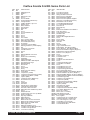
Crathco Granita G&MG Series Parts List ............27
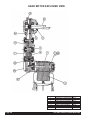
Gear Motor Exploded View ..................................28
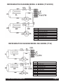
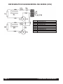
Refrigeration Diagrams....................................29-30
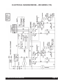
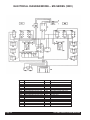
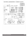
Electrical Diagrams..........................................31-33

Page 2 G & MG Series Granita Machine
Introduction and Warnings
This instruction manual is an important part of this Granita machine and must be kept for future reference.
Carefully read the warnings contained in this instruction manual before installing and operating this Granita
machine.
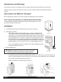
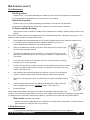
Instructions For Machine Transport
NOTE: Refrigeration equipment must remain upright to avoid damage to the compressor
In order to prevent the oil contained in the compressor from flowing into the cooling
circuit, it is necessary to always ship, carry, store and handle this Granita machine in
an upright position, following the instructions located on the packaging. Never ship,
carry, store or handle unit on its side.
Installation
1.) Cut banding straps from box and lift the box off the machine (see fig. A).
2.) Positioning the machine
• The machine must be well ventilated. Leave an 8” (20 cm) clearance on the
sides and back of the machine to allow proper ventilation. Installation of the
machine near a heat source should be avoided. Some heat sources you should
avoid locating this unit too close to are ovens, coffee machines, cold or frozen
beverage dispensers or ice machines (equipment with compressors that expel
hot air through its vents). Machines should also not be positioned near dust pro-
ducing units such as a Powdered Cappuccino or Cocoa dispenser. A room tem-
perature between 59°F (15°C) and 77°F (25°C) is recommended (see fig. B).
• The lit merchandising covers are reversible (front to back) depending upon the
needs of the operator (see fig. B).
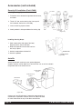
3.) Remove Shipping Pin
• Lift up and remove rear back-lit merchandiser panel (see fig. C). NOTE: Some units may have dual rear
back-lit merchandiser panels, these function in the same manner as the single panel rear merchandisers.
• Pull out each pin attached to each tag (see fig. D)
• Replace rear back-lit merchandiser panel (see fig. E).
(Figure A)
(Figure B)
(Figure C)
(Figure D)
(Figure E)
Attention: Shipping pin attached to tag located behind
each bowl must be removed before starting machines.
!
8"
(20 cm)

G & MG Series Granita Machine Page 3
Installation (cont.)
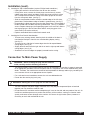
4.) Installing the Top Lid Merchandiser (requires Phillips head screwdriver)
• Unplug the cord to the lid and remove the lid from the machine.
• On top of the cover, remove the 4 hole plugs over the front (2) screws,
middle (near rocker switch) and back screws then remove these 4 screws
with a Phillips head screwdriver. Remove the black top part of the cover
from the clear plastic base. (see fig. E)
• Slide the merchandiser header around the outside edge of the lid’s clear
plastic base. Position bottom edge of header in grooved area. (see fig. F)
• Reassemble the black top cover onto the clear plastic base. The top edge of
header should slide into black top cover grooved area. (see fig. F) Replace
screws. Replace hole plugs (the angled plugs goes in the rear hole, and the
two large plugs go in the two front holes and the small plug goes in the
center hole by the rocker switches).
• Replace assembled lid on machine and reattach cord.
5. Installing the Rear Back-lit Merchandiser
• To remove any existing artwork, bend or pinch the middle of the back-lit
merchandiser and pull it from the rear merchandising display casing.
(see fig. G)
• To insert new art, slide the left corner edges into the left top and bottom
casing edges. (see fig. H)
• Slightly bend art and insert the right side of art into the right top and bottom
casing edges. (see fig. H)
• Smooth out art until all edges are properly inserted into the casing.
Connection To Main Power Supply
• The electrical safety of this Granita machine can only be achieved if the machine is properly connected
to an appropriate grounded, electrical receptacle that is in compliance with current national safety stan-
dards. Therefore, the manufacturer cannot be held responsible for damage and/or injury caused by fail-
ure to connect the unit to an appropriate source of power.
• For a safe and correct installation, connect the unit to a dedicated outlet.
• Do not alter the cord or plug in any way.
• The entire length of the power supply cord must not, in any way, be compressed (bent or bunched
together) nor may extension cords be used.
• Do not obstruct the ventilation and heat dispersion grill vents on the side and rear panels of the unit. An
insufficient ventilation process may reduce the efficiency of the machine, causing it to function inade-
quately, and cause serious damage to the machine. A minimum of eight inches (20cm) clearance is
necessary on each side and behind the unit.
Attention: Altering the cord or plug will void the warranty.
!
Attention: Before inserting the plug into the electrical
outlet, carefully read the following precautions.
!
(Figure E)
(Figure F)
(Figure G)
(Figure H)

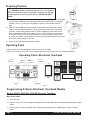
Operating Panel -Electronic Touchpad
Programming G Series Electronic Touchpad Models
Models G23-2B, G235-2B & G236-2B Electronic Touchpad:
Main Power Switch:
1.) Turns unit ON.
2.) Selects 12/24 time or FÞ/CÞ temperature display when turned ON while simultaneously depressing the auger
button.
3.) Sets current time when turned ON while simultaneously depressing the “Mode/Press To Select Function”
button.
Page 4 G & MG Series Granita Machine
(Figure L)
Auger ON/OFF
COLD
FROZEN
OFF
COLD
AUGER ON/OFF
PRESS TO SELECT
FUNCTION
FROZEN
OFF
Press To Select
Function
ON
AUTO TIMER
OFF
AUTO TIMER
Preparing Product
1.) If using product concentrate (instead of ready-to-use product), dilute and mix the prod-
uct with water, according to the directions given by the manufacturer, in a separate
container (see fig. I). Never pour dry powder, crystals, or concentrate into a dry
bowl.
2.) Slide the merchandising lid either forward or toward the back of the bowl until the
“stops” reach the edge of the bowl. (It is not necessary to remove the merchandis-
ing cover.) When sliding lid back make sure that no droplets of water come off lid.
Pour the prepared product into the bowl (see fig. J). Do not spill any material on lid
or on bowl. There is a minimum and maximum fill line on the bowl. Do not overfill
or run the unit without enough product. Running unit with product below the minimum
full line may cause damage to the unit.
3.) Insert the plug into a dedicated electrical outlet.
Operating Panel
In order to access the operating panel, lower the cover (A) as shown
in figure K. To lower the cover use a coin or other object to turn the keyless lock to the horizontal position.
(Figure J)
(Figure I)
(Figure K)
Attention: Make sure that the mixture has a 13% minimum
Brix (sugar content). A lower concentrate could seriously damage
the mixing parts, as well as the gear motors. NEVER USE ONLY
WATER.
!
LED

G & MG Series Granita Machine Page 5
Model G23-2B Electronic Touchpad (cont.):
Auger ON/OFF Button:
1.) Turns auger ON and OFF when main power switch is ON.
2.) Must be ON to permit defrost time to be reset.
3.) Must be ON to activate the “Mode/Press To Select Function” button to select manual “OFF”, “FREEZE” or
“COOLING” functions.
Mode/Press To Select Function Button:
1.) Used to manually select “OFF”, FREEZE” or “COOLING” functions when auger is turned ON.
2.) Accesses defrost timer reset mode when depressed for an extended period when auger is turned ON.
3.) Locks in hours, minutes and final time settings after they are reset using the “Auto Timer” button.
4.) Does not function when light on “Auto Timer” button is illuminated.
“Auto Timer” button
1.) Turns auto defrost mode ON or OFF (light on switch indicates when auto defrost mode is activated).
2.) Used to adjust the hours and minutes settings when readjusting current time or auto defrost timer.
Enter Time Programming on Initial Installation or in the Event of a Time Change:
1.) Turn OFF power switch.
2.) While pressing left “Press To Select Function” button, turn ON power switch while continuing to hold the “Press
To Select Function” button until the display illuminates (hour digits will start to blink).
3.) First set hour by pressing the “Auto Timer” clock button until the appropriate hour is shown (note: when using a
12 hour clock the time is P.M. when the dot at the bottom right corner of the LED is lit; when dot is not lit it is
A.M.)
4.) To set the minutes press the left “Press To Select Function” button, then press the “Auto Timer” clock button
until the appropriate minutes are set.
5.) To save your settings press the “Press To Select Function” button one more time.
Setting Defrost Timer (Night Setting):
1.) Turn power switch ON.
2.) Then press “Auger ON/OFF” button on for the side you are setting.
3.) Then press and hold the “Press To Select Function” button until you hear a long beep and the LED, “cold” and
the “Auto Timer” clock light begins to blink.
4.) Press the “Auto Timer” clock button to set the hour you want it to turn to refrigeration mode and then press the
“Press To Select Function” button to save the setting.

Page 6 G & MG Series Granita Machine
Setting Defrost Timer (Night Setting) (cont.):
5.) Then press the “Auto Timer” clock button to set the minutes to complete time setting that you want it to turn to
refrigeration mode, (defrost mode). Then press the “Press To Select Function” button to save the setting.
6.) Proceed to setting the time you want the machine to turn to freezing mode by following steps 4 and above.
Then press the “Press To Select Function” button to save the time settings for freeze mode. Freeze light
should be blinking.
Note: Once the settings have been saved, the unit will save the settings, even when the power switch is turned OFF.
When the light on the “Auto Timer” clock button is “on”, the defrost timer is activated. To turn OFF the defrost timer,
press the “Auto Timer” clock button(s) until the light(s) on the clock button(s) turns off.
Operate in Automatic Mode (with Defrost Timer Activated):
1.) Turn power switch ON and wait for LED to light up.
2.) Press auger button “ON” for the side you are setting.
3.) To operate in defrost mode press the “Auto Timer” button until it is illuminated.
4.) When setting automatic times, please keep in mind it will take time for the frozen product to become liquid or
vice versa.
Operate in Manual Mode (without Defrost Timer Activated):
1.) Turn power switch ON and wait for LED to light up.
2.) Make sure clock button is OFF (LED light on clock button should not be lit up).
3.) First turn auger on by pressing “Auger ON/OFF” button until it beeps. (Note: The auger must be on before unit
will allow the cooling or freezing mode to activate)
4.) Then select refrigeration or freezing mode by pressing the “Press To Select Function” button until the light
under the selection you desire is lit up. (Note: In the cooling mode, the LED will read the actual temperature of
the product {The temperature setting is preset to NSF standards and is not adjustable.}) In the freezing mode
the LED will read the current time.
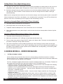
G SERIES MODELS - ERROR MESSAGES
1.) “FILTER CLEANING” ALARM
A filter cleaning alarm will activate when the unit is running hot due to insufficient internal air circulation.
When this occurs a “Filtr” message will appear on the touchpad LED readout and an intermittent audible tone
will also sound to alert the operator of this condition.
The “Filtr” message will appear when the alarm activates (a beeping sound every 4-5 seconds). To determine
the condition that caused the alarm and correct problem, see list of conditions below:
• Condition: The filter is dirty and needs to be cleaned. - Corrective Action: Clean and replace filter following
instructions on page 11 (Removing and Cleaning Filter).
• Condition: The unit is positioned too close to a wall or other object restricting air flow and causing the
machine to run at a higher temperature. - Corrective Action: Reposition unit to maximize ventilation space
(see page 2 - installation figures).
• Condition: The filter is not properly installed. - Corrective Action: Properly install filter see “Removing and
cleaning filter” page 11.
• Condition: The unit has been installed near a heat source, such as a coffee machine, ice maker or cold
beverage machine which expels hot air from its vents, causing the machine to run at a high temperature.
(Installation near a heat source should be avoided) - Corrective Action: Reposition unit to maximize ventila-
tion space (see page 2 - installation figures).

G & MG Series Granita Machine Page 7
G SERIES MODELS - ERROR MESSAGES (CONT.)
2.) “SYSTEM OVER TEMPERATURE” ALARM
• A system over temperature alarm will activate as a safety when the unit has overheated to protect the
compressor.
• The system automatically goes to “OFF” status where the compressor’s operations is stopped, while
augers will keep working to avoid forming ice blocks.
• When this occurs an “Err” message will appear on the touch pad LED readout accompanied by a continu-
ous buzzer sound to alert the operator of this condition.
• When this alarm activates, turn off all switches. Then determine the condition. (See “Filter Cleaning” Alarm
Section for Conditions and Corrective Actions)
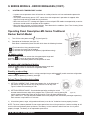
Operating Panel Description-MG Series Traditional
Rocker Switch Model
1.) Turn ON the main power switch (D) (see figure M)
2.) Description of the buttons (see figure cc):
Each bowl is controlled by three switches which have the following functions:
(E) activates the mixing parts/spiral auger
(F) activates the freezing of the product
(G) activates the refrigeration of the product (night/defrost setting)
To obtain a slush:
Select the (E) switch to activate the mixing parts/spiral auger and
select the (F) switch to activate the freeze mode.
Note: There is a 4 minute delay before the compressor will start.
To obtain cold (night/defrost) drinks:
Select the (E) switch to activate the mixing parts/spiral auger and
select the (G) switch to activate the refrigeration mode.
Stand-by mode setting:
Select the (E) switch to activate the mixing parts/spiral auger and the (G) switch to activate refrigeration
mode to keep the product(s) in bowl(s) overnight.
Defrost Timer Operating Instructions
1.) SETTING CURRENT TIME - Rotate the program disc, in the direction of
the arrows, to align the correct time of day with the time of day mark.
Figure H shows the timesetting of 7:00.
2.) SETTING DEFROST MODE - Set the defrost period by pushing the switch
actuator toward the outer edge of the program disc. Freeze time is set by pushing the
switch actuators toward the center of the time switch. Figure N shows a defrost time
from 11:00 to 6:15. The light and dark shaded areas of the program disc indicate day and night respectively.
Each actuator is equivalent to 15 minutes.
3) All switches (power, auger, refrigeration and freeze) must be “on” for defrost timer to properly function.
NOTE: The timer is battery backed. Do not remove power from the unit for greater than 2 weeks as doing so will
result in failure of the battery back-up feature. The battery is nickel cadmium and will last from 6 to 8 years if
properly charged. The battery is not replaceable upon failure.
(Figure N)
(Figure M)

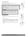
Dispensing Product
To dispense the product, position the cup under the dispensing valve (C)
and lower the dispensing lever (B) (see fig. O).
Adjustments
Consistency Adjustment
1.) Unplug the machine.
2.) Be sure that product in bowl is within proper fill range.(Above the minimum
fill line)
3.) Remove merchandiser.
4.) Change the thickness of the product by turning the screw (D) on the back of
the bowl, as shown on fig. P. Turn the screw clockwise for thinner product or
counterclockwise for thicker product. The indicator gauge (D1), located on
the back of the bowl, shows the degree of adjustment (+/-). (+) = thicker,
(-) = thinner
Note: This (D1) is an indicator gauge only. To adjust consistency, turn screw
on top (D).
Page 8 G & MG Series Granita Machine
(Figure Q)
(Figure P)
Attention: To prevent the product from becoming too thick,
it is necessary to push left “Press To Select Function” and right
“Press To Select Function” keys to cold drink position or to refill
the bowl when the level of the granita inside the bowl is below the
minimum fill line.
!
!
Attention: If the machine is turned off at night, with the bowls filled,
or just partially filled, a layer of solid ice may form on the surface due to the
natural separation of the unmixed (non-moving) product. In this case, before
turning the machine back on, remove the layer of superficial ice to prevent
damage to the mixing auger.
(Figure O)

G & MG Series Granita Machine Page 9
Cleaning and Sanitizing Procedures
Daily Cleaning
For the machine to function properly, it is important that
the cleaning procedures be carried out daily, according
to the following instructions:
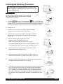
1.) Turn off the / (G, fig. M) refrigeration and / (F, fig. M) freezing
switches and empty the bowl of its remaining product; after draining the prod-
uct from the unit, you can fill the bowl with hot water (not boiling) to help melt
off any sugar deposits. Then drain the water prior to proceeding to step (2).
2.) Unplug the unit.
3) Pull out the mixing rod (E) by pushing it slightly backwards
to remove it from its position (see fig. Q on pg.8).
4.) Unscrew and remove the two knobs (F) then lower the bowl to
drain out any remaining product through the dispensing valve
(see fig. R).
5.) Remove and disassemble the dispensing valve:
• Remove the pin (G) as shown (see fig. S).
Then, remove the handle (B) sliding it from its seat.
• Simultaneously apply pressure to the two securing tabs (H) and
lift the dispensing valve (C) to pull it out of its position (see fig. T).
6.) Remove the bowl (L) by unscrewing the two knobs (F) and
pulling it downwards as shown in fig. U.
7.) Unscrew the securing bolt (M) clockwise. Pull off the auger (N)
and remove the shaft seal (O) and the bowl seal (P) (see fig. V).
8.) Remove the drain tray by lifting up on the front edge, while lowering the
rear edge, and then lift it off the unit (see fig. W).
9.) Thoroughly wash each part that has been removed in steps 1-8 and the base
(Q), as well as the freezing cylinder (R) with warm water and mild dish-
washing detergent. Rinse well with clear water and allow to air dry (see
fig. X). Avoid the use of abrasive cleaners which can damage the finish.
Do not put in dishwasher. Dishwasher may damage some parts such as
the clear plastic auger gears and top mixing bar. Reassemble with clean
hands.
(Figure V)
(Figure W)
(Figure X)
(Figure U)
!
Warning Disconnect the unit from its power supply
prior to cleaning or sanitizing the unit. Failure to do so may
result in electric shock.
(Figure R)
(Figure S)
(Figure T)

Page 10 G & MG Series Granita Machine
Cleaning and Sanitizing Procedures (con’t)
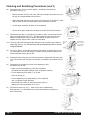
10.) Reassemble the mixing unit back together, according to the following
procedures (see fig. Y):
• Moisten the bowl seal (P) with water and slip it into place at the back of cylin-
der with ribs angled toward back of freezer.
• Apply food grade lubricant to the inside of the shaft seal (O) and put the shaft
seal (O) back on with the flared end of seal toward back of freezer.
• Put the auger assembly (N) back on the evaporator.
• Secure all the parts in place by screwing on the bolt (M) counterclockwise.
11.) Reassemble the bowl (L), positioning it into place. Make sure that the bowl fits
tightly to the bowl seal (see fig. Z). We also suggest that the rear part of the
bowl be moistened with water or lightly lubricated at the point where it fits
together with the seal to make it easier to install bowl.
11a.) The lower right and left bowl flanges should fit on the outside of each black tri-
angle edge (see fig. AA). The lid cover will not fit properly if this is not cor-
rectly positioned.
12.) Secure the bowl (L) by keeping it lifted until the bolt (M) is aligned with its hole
(S), then tightly screw on the knobs (F) without exerting excessive pressure to
avoid cracking the bowl (see fig. BB).
13.) Reassemble the mixing rod (O) so that its gears are aligned with the lower gear
ring. This will allow the front pin to fit perfectly in its position on the bowl (see fig.
CC).
14.) Reassemble in sequence the parts of the dispensing valve
as follows (see fig. DD).
• Make sure that the dispensing valve seat is properly
lubricated with food-grade lubricant (such as Haynes Lubrifilm).
• Put the dispensing valve body (T) in its seat.
• Insert the spring (U).
• Put the dispensing valve upper body (V) into its position
until it completely snaps into place.
• Reassemble the handle (B) and insert retaining pin (G)
following the same procedures in #5, fig. S.
15.) Reinstall the drain tray (fig. T). Make sure that the condensation
drainage tube (J) is reinserted into its correct fixed position, allowing it to
drain into the tray.
(Figure BB)
(Figure CC)
(Figure AA)
(Figure DD)
(Figure Z)
Bowl outside
corner must be
over the white
plastic edge.
(Figure Y)

G & MG Series Granita Machine Page 11
Cleaning and Sanitizing Procedures (con’t)
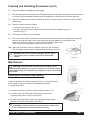
16.) Plug the unit back into appropriate power supply.
17.) After the cleaning and reassembly of the mixing parts and bowl as per above instructions, fill the bowl with a
mix of water and an approved cleaning solution (example kay5), according to the measures specified.
18.) Start the mixing part of the machine for about 10 minutes to sanitize all parts. Follow the cleaning solution
specifications.
19.) Drain the cleaning solution as follows:
• Unscrew the two knobs (F) see fig. U);
• then lower the bowl to drain out any remaining product through the dispensing valve (C)
(as shown in fig. U).
20.) Screw again the knobs (F) to fix the bowls.
21.) With a clean cloth wash the underside of the lamp cover with warm water and a mild detergent. Allow this
part to air dry and then wipe it with a clean cloth which has been dipped in the sanitizing mixture.
Prepare a minimum of 4 gallons (15 liters) of sanitizing solution (Stera Green
Label or equivalent) following the manufacturer’s instructions.
Note: Add 4 ounces of Stera Sheen to 4 gallons (15 liters) of 120° Fahrenheit
(50° Centigrade) water to achieve a concentrate of 100 parts per million.
Warning: Lamp cover must be unplugged. Electric shock
could occur if cover or power cord come in contact with
solution.
Maintenance
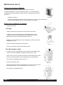
Removing and cleaning the filter (Weekly)
This should be done weekly or more often if necessary.
In order to guarantee an efficient refrigerating system, it is essential that the
filter be properly cleaned, according to the following procedures:
1) Unplug the machine.
2) Unscrew the knob (K) in order to remove back panel (see fig. FF).
3) Remove the filter (W) held inside the back panel (X) and clean
it properly using water or vacuum (see fig. GG).
4) Place the cleaned filter back inside back panel and reinstall the back
panel on the machine by screwing in the knob (K).
(Figure FF)
(Figure GG)
Warning: Disconnect the unit from its power supply prior to
performing any maintenance procedures. Failure to do so could result in
electric shock, injury from hazardous moving parts or serious burns from
hot surfaces.
Attention: Failure to maintain a clean filter and condenser will
cause damage to the unit not covered by warranty.
!
(Figure EE)
!
!

Page 12 G & MG Series Granita Machine
Maintenance (con’t)
Cleaning the Condenser (Monthly)
This cleaning should be done monthly or more often if necessary.
In order to guarantee an efficient refrigerating system, it is essential that the
condenser be properly cleaned at regular intervals, according to the following
procedures:
• Unplug the machine.
• Remove the back panel and filter. Using a dry brush or vacuum, remove the dust that
has accumulated between the fins of the condenser (see fig HH).
Replacing the Lightbulbs (As Needed)
• Unplug the machine.
Lid Lights
• Unplug the cord to the lid and remove the lid from the machine.
• In order to access the lightbulb in the merchandising cover, insert
a quarter in the slot on the small panel on the top of the cover (DA)
and rotate the quarter to pop the panel open (see fig. II).
• Holding the merchandising cover with the top open, carefully remove the
lightbulb (see fig. JJ).
• Insert the new bulb and replace the light cover.
• Place lid on machine and plug lid cord back into lid.
Rear Merchandiser Lights
• In order to access the lightbulb from the rear back-lit merchandiser (BB),
remove the rear merchandiser by sliding it upwards (see fig. KK).
NOTE: Some units may have dual rear backlit merchandiser panels, these
function in the same manner as the single panel rear merchandisers.
• Then remove the lightbulb(s) (BA) (see fig. LL).
• Insert the new bulb(s) (BA).
• Reassemble the rear back-lit merchandiser (AA) making sure that its slots
are inserted properly in the relevant brackets (CA) (see fig. LL).
• Plug machine into dedicated outlet.
(Figure II)
(Figure JJ)
(Figure KK)
(Figure LL)
(Figure HH)

G & MG Series Granita Machine Page 13
Maintenance (con’t)
Seal Maintenance
Bell Shaped Seal
• Replace every 1 to 6 months depending on conditions of use and level of maintenance and lubrication.
This part should be lubricated during re-assembly after every cleaning.
Spindle Bushing Seal
• Replace every 6 to 12 months depending on conditions of use and level of maintenance.
Replacement of spindle bushing should ONLY be done by a qualified service technician.
To Replace Spindle Bushing:
Tools required: Power screwdriver, Rubber mallet, Replacement Kit #90104, spindle bushing extraction tool
#90544
Each PM kit # 90104 contains 2 bell shaped shaft seals, 2 spindle bushing seals, 4 dispense valve o-rings, 1 lami-
nated care and cleaning card and one PM checklist.
1. Empty product bowl and disassemble as if for cleaning. Spindle bushing seals should be replaced every
6-12 months and bell-shaped shaft seals should be replaced once every 1-6
months depending on conditions of use and maintenance.
2. Slide the threaded metal cylinder on the drive shaft so that the flat surface meets
the face of the evaporator cylinder.
3. Thread the two tapping screws (max length 1 1/8”) through the holes in the tool
and into the spindle bushing seal. Use of a power screwdriver is suggested. (See
Figure MM)
4. Screw the outer cylinder of the extracting tool on to the metal cylinder by rotating
clockwise until it is fully connected.
5. Continue turning the outer cylinder clockwise until the spindle bushing seal is removed.
If necessary, apply higher torque by inserting a screwdriver in the holes of the outer
cylinder. (See Figure NN)
6. After extracting the old spindle bushing seal, position a new one in the evaporator
cylinder. The gasket (black side) should be facing the inside of the evaporator.
7. Position the inserting pipe so that it’s smaller diameter touches the spindle bushing
seal.
8. Push the spindle bushing seal in by tapping on the pipe with a rubber mallet. Be
sure the spindle bushing seal is completely
in place. (See Figure OO)
9. Reassemble bowl.
When replacing the spindle bushing be sure to check the condition of the driveshaft. If the
surface is not smooth and the driveshaft is not secure, then replace the driveshaft while replacing the spindle bush-
ing. Replacement of a driveshaft should only be done by a qualified service technician using PM kit #90110.
Bowl Gasket (located at rear of bowl)
• Replace as necessary depending on the conditions of use and level of maintenance. This part should be
lubricated during re-assembly after every cleaning.
O-Ring Maintenance
•O-rings should be replaced every 6 to 12 months or as necessary where wear is apparent.
Figure MM
Figure NN
Figure OO

Page 14 G & MG Series Granita Machine
Crathco Granita Preventive
Maintenance (PM)
Checklist for Kit 90566 -
Serial # 11259 and above
(and units with lower serial #’s that have been
converted to stainless steel shafts - units with
black stainless shafts will need to be converted
using PM Kit # 90110B)
A preventive maintenance visit should be performed every 6 months. In addition, air filter should be cleaned weekly,
and every three months the condenser should be cleaned, and the rubber shaped bell shaft seals should be
replaced. Failure to complete PM’s every 6 months is considered abuse of the machine, and therefore voids the
warranty. Proof of PM must be documented with Grindmaster Corporation to maintain warranty coverage. To docu-
ment your PM, complete this form with signatures, place used/worn parts that were replaced during the PM inside
envelope, and mail to Grindmaster Corporation. Parts returned should include 2 evaporator seals, 2 rubber bell
shaped shaft seals, valve o-rings and shafts (if applicable). First PM on serial numbers 11259 to 12202 should also
include kit number 90225 (one per serial number).
The following procedures should be performed during a Preventative Maintenance visit, using PM kit # 90566
or 90110B.
Document model and serial number of equipment and record above.
Check product temperature and consistency for proper setting - adjust if necessary.
Insure product is being mixed properly and is within specification (check and document brix - most products
should be around 13% - refer to product manufacturer’s recommendations for exact recommended brix).
Record Brix reading here: Left Bowl _____ Right Bowl _____
Check for leaks at gaskets, o-rings, front shaft seal, etc.
Empty product from bowls and disassemble unit completely.
Clean and sanitize all disassembled parts.
Clean and sanitize top tray and freezing barrel.
Clean out condensation tube with sanitizer and long brush.
Check condition of all panels, bowls, lids - replace if necessary.
Check mixing rods and augers for wear, check mixing rod bearing for wear - replace if necessary.
Check for bowl knobs (two per bowl to lock down bowl in front) - replace if necessary.
Check operation of lights in lid and rear of unit (if equipped) - replace light bulbs if necessary.
Clean re-usable air filter. Check condition of filter and replace if necessary.
Clean condenser.
Check condition of bowl gaskets and replace if necessary.
Replace all o-rings on dispense valves and lubricate.
Check drive shaft. Replace if necessary, using PM kit #90110B in place of 90566 above.
Replace evaporator seal in front of evaporator. (use brass tool, included, to slide seal onto shaft, and use the
white tool to tap seal into place. Be sure to lubricate seal with food grade grease first)
Replace bell shaped rubber shaft seal on front of freezing barrel (generously lubricate inside seal)
Lubricate parts where appropriate (dispense valve o-rings, inside of shaft seal, inner rim of bowl where it meets
with the bowl seal)
Re-assemble unit and refill with product
Verify and document defrost timer setting and operation and time of day setting and adjust if necessary.
Check thermostat setting on MG models. Thermostat setting should be between 1-1/2 and 2.
Verify compressor operation and freezer controller operation.
Verify ventilation is adequate (8” on both sides and back)
Check electrical connections and wiring.
Check fan operation (1 condenser fan and 2 gear motor fans) and clean fan or blades if necessary.
Review proper periodic care and cleaning instructions (disassembly, cleaning, sanitizing, lubrication and
re-assembly) with store personnel. Review proper product mixing and handling instructions with store personnel
Demonstrate and train store personnel to follow proper procedures (stress importance of store level
maintenance such as lubrication and filter cleaning).
Make sure store personnel have appropriate supplies (lubricant and sanitizer) to care for machine.
Model # ___________________________
Serial # ____________________________
Date: ______________________________
PM by _____________________________
Of Company ________________________
Store Name/# _______________________
Address ___________________________
__________________________________
Store Mgr Name ____________________
Signature __________________________

Crathco Granita Preventive
Maintenance (PM)
Checklist for Kit 90104 -
Serial # 11258 and below*
(If unit has been converted to unhardened
stainless shaft system, then use kit #90566
instead. )
A preventive maintenance visit should be performed every 3
months. Failure to complete PM’s every 3 months is considered abuse of the machine, and therefore voids the war-
ranty. Proof of PM must be documented with Grindmaster Corporation to maintain warranty coverage. To document
your PM, complete this form with signatures, place used/worn parts that were replaced during the PM inside enve-
lope, and mail to Grindmaster Corporation. Parts returned should include 2 spindle bushing evaporator seals, 2 rub-
ber bell shaped shaft seals, valve o-rings and shafts (if applicable).
The following procedures should be performed during a Preventative Maintenance visit, using PM kit # 90104:
Document model and serial number of equipment and record above.
Check product temperature and consistency for proper setting - adjust if necessary.
Insure product is being mixed properly and is within specification (check and document brix - most products
should be around 13% - refer to product manufacturer’s recommendations for exact recommended brix).
Record Brix reading here: Left Bowl _____ Right Bowl _____
Check for leaks at gaskets, o-rings, front shaft seal, etc.
Empty product from bowls.
Disassemble unit completely.
Clean and sanitize all disassembled parts.
Clean and sanitize top tray and freezing barrel.
Clean out condensation tube with sanitizer and long brush.
Check condition of all panels, bowls, lids - replace if necessary.
Check mixing rods and augers for wear, check mixing rod bearing for wear - replace if necessary.
Check for bowl knobs (two per bowl to lock down bowl in front) - replace if necessary.
Check operation of lights in lid and rear of unit (if equipped) - replace light bulbs if necessary.
Clean re-usable air filter if so equipped (standard on G & MG models, optional on ID models). Check condition
of filter and replace if necessary.
Clean condenser.
Check condition of bowl gasket and replace if necessary.
Replace all o-rings on dispense valves and lubricate.
Check drive shaft. If surface is not smooth or the drive shaft is not secure (excessive movement in and out) use
PM kit #90110, or 90110B in place of 90104 above.
Replace spindle bushing seal in front of evaporator using extraction tool.
Replace bell shaped rubber shaft seal on front of freezing barrel (generously lubricate inside seal)
Lubricate parts where appropriate (dispense valve o-rings, inside of shaft seal, inner rim of bowl where it meets
with the bowl seal)
Re-assemble unit and refill with product
Verify and document defrost timer setting and operation and time of day setting and adjust if necessary.
Check thermostat setting on ID and MG models. Thermostat setting should be between 1-1/2 and 2.
Verify compressor operation and freezer controller operation.
Verify ventilation is adequate (8” on both sides and back).
Check electrical connections and wiring.
Check fan operation (1 condenser fan and 2 gear motor fans) and clean fan or blades if necessary.
Review proper periodic care and cleaning instructions (disassembly, cleaning, sanitizing, lubrication and
re-assembly) with store personnel. Review proper product mixing and handling instructions with store personnel.
Demonstrate and train store personnel to follow proper procedures (stress importance of store level
maintenance such as lubrication and filter cleaning).
Make sure store personnel have appropriate supplies (lubricant and sanitizer) to care for machine.
Model # ___________________________
Serial # ____________________________
Date: ______________________________
PM by _____________________________
Of Company ________________________
Store Name/# ______________________
Address ___________________________
__________________________________
Store Mgr Name ____________________
Signature __________________________
G & MG Series Granita Machine Page 15

Page 16 G & MG Series Granita Machine
Accessories (not included)
Security Kit Installation (Part # 3468)
Installing Locking Clip
1. Pinhead must be located on righthand side of valve,
as shown.
2. The 0.125” slot, on the locking clip, lines up with
the horizontal shelf on the valve body.
3. Insert the locking clips as shown.
4. Attach padlock in hole provided on the locking clip.
Installing Security Straps
1. Hook straps under side edge of the bowl,
beginning at the front of the bowl.
2. Slide the straps back on the bowl until the
are firmly in place
3. Interlock straps above the bowl lid.
4. Attach the padlock.
Autofills
Attach liquid autofill systems to your granita dispenser.
Autofills minimize manual labor to mix and refill the unit, as well as maintain
the product bowl at an attractive level.
Contact your local Grindmaster Corporation representative or
Grindmaster Corporation customer service at (800) 695-4500
for more information on any of the above accessories.
PULL HANDLE
PIN HEAD
LOCKING CLIP IN
LOCK POSITION
LOCKING CLIP
HORIZONTAL
SHELF
HOLE FOR
PADLOCK
VALVE BODY
0.125”
SLOT
GRANITA BOWL
SECURITY STRAP
(Figure PP)
(Figure QQ)
(Figure RR)
BIB Product
Product Delivery
System
Water line
Product Filling
System

G & MG Series Granita Machine Page 17
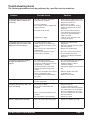
Troubleshooting Guide
The following procedures must be performed by a qualified service technician.
Problem Possible Cause Solution
The machine does not cool, or cools
only partially, but the compressors
are running
The machine does not cool or cools
only partially, but one or more of the
compressors are not running
The machine over-freezes, making
the auger movement slow or
stopped
The machine is noisy
The main power switch is “On”. The
unit is not running.
Product is leaking out of the bowl
• Allow at least 8” (20cm) between the
machine and anything next to it; keep
away from heat sources
• Return to freeze mode
• Remove the side panels. Using a
brush or compressed air clean the
condenser
• Check the fan motor’s electrical
connections and, if disconnected,
reconnect. If still not operating,
replace the motor
• Locate the leak, eliminate it and
recharge the system
• Replace the malfunctioning
components
• Check the contacts and correct those
that are incomplete
• Replace the compressor(s)
• Check the electrical connections to
the PC board as well as the
transformer feeding the PC board
and correct
• Check the product brix and correct
• Reset the screw toward the “-”
position to produce a thinner
consistency product
• Using pliers, straighten the limit switch
arm
• Add more product or turn the
refrigeration “Off”
• Replace the PC board
• Check and correct
• Replace the fuse(s)
• Clean the condenser or add
ventilation space around the machine
(the cutout switch reset is automatic
when the conditions are corrected)
• Check the contacts and correct those
that are incomplete
• Replace the switch
• Replace or reposition the seals
• The space around the machine is
inadequate for ventilation
• Freezer is in defrost
• The condenser fins are clogged with
airborne particles
• Fan motor is not running
• Refrigerant is leaking
• Electrical components of the
compressor(s) are not functioning
• Some electrical connections are not
complete
• One or more of the compressors are
malfunctioning
• No current is coming to the “com-
pressor delay” PC board
• The product brix is too low
• The screw setting for the product
consistency control system is set too
far toward the “+” position
• The limit switch arm is bent away
from the gearmotor and prevents
contact
• The level of the product in the bowl is
too low, exposing the auger
• The compressor PC board contacts
don’t open
• The fan motor blades are hitting
internal components
• The fuse(s) are blown
• The pressure cutout switch has
activated
• Some electrical connections are not
complete
• The main power is not functioning
• One of the bowl seals is not in place

Page 18 G & MG Series Granita Machine
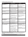
Troubleshooting Guide (cont’d)
Problem Possible Cause Solution
If you still need help, call our service department at (800) 695-4500 (USA & Canada only) or (502) 425-4776 (Monday
through Friday, 8 am - 6 pm EST) or an authorized service center in your area. Please have the model and serial
numbers ready so that accurate information may be given.
Prior authorization must be obtained from Grindmaster Corporation’s Technical Services Department for all
warranty claims.
Product is leaking from the
dispensing valve
Product is flowing into drain tray
through drainage tube
The auger and/or the upper mixing
unit is not turning
The auger and/or the upper mixing
units are creating noises as they
rotate
There is no light in the
merchandising lid or rear
merchandising panel
The cover does not fit properly on
the bowl
“Filtr” or “Err” message appears on
the touchpad LED readout
• Reassemble and replace
• Clean and lubricate the valve and
valve cylinder with the lubricant pro-
vided with the machine
• Replace the o-rings
• Find the seal and put it back in place
• Replace the damaged/worn seal and
check the condition of the driveshaft.
• Turn auger on
• Check the contacts and correct the
ones that are incomplete
• Replace the gear motor(s)
• Check and correct
• Check the product brix and correct
• Replace or Clean and lubricate with
the lubricant provided with the
machine
• Check and correct
• Replace (See “Changing the lightbulb”
section in this manual)
• Replace
• Replace
• Remove bowl and position properly
• Clean and replace filter following
instructions on page 11 (Removing
and Cleaning Filter)
• Reposition unit to maximize ventilation
space (see page 2 - installation figures)
• Properly install filter see “Removing and
cleaning filter” page 11
• Reposition unit to maximize ventilation
space (see page 2 - installation figures)
• The dispensing valve has been incom-
pletely or incorrectly replaced in its
position
• The free movement of the dispensing
valve is impeded
• Dispensing valve o-rings are damaged
• The bell shaped “shaft” seal between
the front of the cylinder and the auger
hub has not been reinstalled properly
• The bell shaped “shaft” seal or the
spindle bushing seal is damaged or
worn
• Auger not turned on
• Some electrical connections are not
complete
• The gear motor(s) are malfunctioning
• The large red bowl seal is not in
position, causing the gear teeth not to
mesh
• The product brix is incorrect
• The bell shaped “shaft” seal has been
replaced without lubrication or is dam-
aged
• The auger has been incompletely or
incorrectly reassembled (ie the
auger’s gear pins are not properly
seated)
• The light bulb is burnt out
• The 5 Amp fuse between the trans-
former and the lamp is blown
• The transformer is blown
• The bowl is incorrectly positioned (the
lower, outside corner is not over the
lower, outside base piece)
• The filter is dirty and needs to be
cleaned
• The unit is positioned too close to a
wall or other object restricting air flow
and causing the machine to run at a
higher temperature
• The filter is not properly installed
• The unit has been installed near a
heat source, such as a coffee
machine, ice maker or cold beverage
machine which expels hot air from its
vents, causing the machine to run at a
high temperature. (Installation near a
heat source should be avoided)

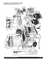
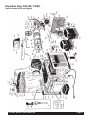
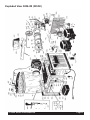
G & MG Series Granita Machine Page 19
Exploded View MG23-2B (115/60)
(for units up to serial number 8195)

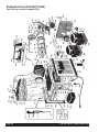
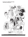
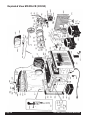
Page 20 G & MG Series Granita Machine
Exploded View G23-2B (115/60)
(for units up to serial number 8195)
Page is loading ...
Page is loading ...
Page is loading ...
Page is loading ...
Page is loading ...
Page is loading ...
Page is loading ...
Page is loading ...
Page is loading ...
Page is loading ...
Page is loading ...
Page is loading ...
Page is loading ...
Page is loading ...
Page is loading ...
Page is loading ...
-
 1
1
-
 2
2
-
 3
3
-
 4
4
-
 5
5
-
 6
6
-
 7
7
-
 8
8
-
 9
9
-
 10
10
-
 11
11
-
 12
12
-
 13
13
-
 14
14
-
 15
15
-
 16
16
-
 17
17
-
 18
18
-
 19
19
-
 20
20
-
 21
21
-
 22
22
-
 23
23
-
 24
24
-
 25
25
-
 26
26
-
 27
27
-
 28
28
-
 29
29
-
 30
30
-
 31
31
-
 32
32
-
 33
33
-
 34
34
-
 35
35
-
 36
36


Crathco / Grindmaster G23-2B User manual
- Type
- User manual
Ask a question and I''ll find the answer in the document
Finding information in a document is now easier with AI
Related papers
-
Crathco / Grindmaster ID2.2 Operating instructions
-
Crathco / Grindmaster C-2D User manual
-
-
-
-
-
-
Crathco / Grindmaster 5711 User manual
-
-
Other documents
-
IBE KL200E User manual
-
Hobart HCM450 Cutter Mixer Bowl Seal User manual
-
Hendi 274224 User manual
-
-
Scotsman CME 48" Air infiltration Kit - 17-2883-01 Operating instructions
-
EASTMAN 60248 Installation guide
-
 Cornelius Ice Peak User manual
-
-
Grindmaster PM45-B User manual
-
Alvin Drawing Table "Caddy" TT499 User manual
