Page is loading ...

Operator’s Manual
IMPORTANT: Read this manual carefully. It contains information about your
safety and the safety of others. Also become familiar with the controls and
their proper use before you operate the product.
FORM NO. 3317–988GB Rev. A
44” Grass
Collection System
for
GM & PL 117, 118, & 120
Model No. 30751 – 690001 & Up

Printed in USA
Introduction
We want you to be completely satisfied with your
new product, so feel free to contact your local
Authorized Service Dealer for help with service,
genuine replacement parts, or other information you
may require.
Whenever you contact your Authorized Service
Dealer or the factory, always know the model and
serial numbers of your product. These numbers will
help the Service Dealer or Service Representative
provide exact information about your specific
product. You will find the model and serial number
plate located in a unique place on the product as
shown below.
1
1815
1. Model and Serial Number Plate
For your convenience, write the product model and
serial numbers in the space below.
Model No:
Serial No.
The warning system in this manual identifies
potential hazards and has special safety messages that
help you and others avoid personal injury, even death.
DANGER, WARNING and CAUTION are signal
words used to identify the level of hazard. However,
regardless of the hazard, be extremely careful.
DANGER signals an extreme hazard that will cause
serious injury or death if the recommended
precautions are not followed.
WARNING signals a hazard that may cause serious
injury or death if the recommended precautions are
not followed.
CAUTION signals a hazard that may cause minor or
moderate injury if the recommended precautions are
not followed.
Two other words are also used to highlight
information. “Important” calls attention to special
mechanical information and “Note” emphasizes
general information worthy of special attention.
The left and right side of the machine is determined
by sitting on the seat in the normal operator’s
position.

1
Contents
Page
Safety and Instruction Decals 2. . . . . . . . . . . . . .
Installation 3. . . . . . . . . . . . . . . . . . . . . . . . . . . . .
Loose Parts 3. . . . . . . . . . . . . . . . . . . . . . . . .
Removing Blower Assembly 12. . . . . . . . . . .
Operation 13. . . . . . . . . . . . . . . . . . . . . . . . . . . . . .
Operating Characteristics 13. . . . . . . . . . . . . .
Page
Maintenance 15. . . . . . . . . . . . . . . . . . . . . . . . . . . .
Service Interval Chart 15. . . . . . . . . . . . . . . .
Cleaning 16. . . . . . . . . . . . . . . . . . . . . . . . . . .
Inspecting the Blades 16. . . . . . . . . . . . . . . . .
Storage 16. . . . . . . . . . . . . . . . . . . . . . . . . . . .

2
Safety and
Instruction Decals
ON FRONT OF BLOWER
HOUSING
(Part No. 82–5510)
ON BLOWER HOUSING
AND DEFLECTOR
(Part No. 54-9220)
See Traction Unit Operator’s Manual for
Glossary of Safety Symbols
The following safety and instruction decals are affixed to the unit. If any decal
becomes illegible or damaged, install a new decal. Part numbers are listed below
and in your Parts Catalog. Replacement decal can be ordered from your local
Authorized Toro, Proline Service Dealer.

3
Installation
Loose Parts
Note: Use the chart below to identify parts used for assembly.
DESCRIPTION QTY. USE
Valve Stem Extension
Wheel Weight
Capscrew–5/16-18 x 4” (102 mm)
Flat Washer–5/16 (8 mm)
1
1
2
2
Install Wheel Weight
Carriage Bolt–5/16-18 x 5/8” (16 mm)
Lock Nut–5/16-18
Carriage Bolt–5/16-18 x 7/8” (22 mm)
2
5
3
Install Front Blower Mounting Bracket
Carriage Bolt–5/16-18 x 5/8 (16 mm)
Keps Lock Nut–5/16-18
2
2
Install Rear Baffle
Self-Tapping Screw–1/4-20 x 7/8” (22 mm)
Washer–1/4” (6 mm)
Capscrew–1/4-20 x 3/4” (19 mm)
Lock Nut–1/4-20
2
2
4
4
Install Center Ring Baffle
Carriage Bolt–5/16-18 x 5/8 (16 mm)
Lock Nut–5/16-18
Capscrew–1/4-20 x 3/4” (19 mm)
Lock Nut–1/4-20
2
2
2
2
Install Right Ring Baffle
Capscrew–1/4-20 x 3/4 (19 mm)
Lock Nut–1/4-20
3
3
Install Left Ring Baffle
Carriage Bolt–1/4-20 x 5/8” (16 mm)
”Keps Lock Nut–1/4-20
Carriage Bolt–5/16-18 x 5/8” (16 mm)
Lock Nut–5/16-18
1
1
1
1
Install Front Baffle
Carriage Bolt–5/16-18 x 5/8” (16 mm)
Flat Washer–5/16” (8 mm)
Lock Nut–5/16-18
2
2
2
Install Idler Assembly
Capscrew–5/16-18 x 1” (25 mm)
Lock Nut–5/16-18
Reinforcing Plate
6
6
1
Install Hopper Brackets

Installation
4
DESCRIPTION USEQTY.
Capscrew–5/16-18 x 2” (51 mm)
Lock Nut–5/16-18
5
5
Install Hopper Frame
Knob
Washer–5/16” (8 mm)
2
2
Mount Grass Deflector
Install Wheel Weight
(Left Front Wheel Only)
Note: If unit is equipped with Optional Brake
Kit, refer to Brake Kit Instructions for
additional information on mounting
wheel weight.
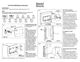
1. Remove cap from valve stem and install valve
stem extension.
2. Slide wheel weight into mounting position over
valve stem, aligning weight with (2) mounting
holes in wheel.
3. Secure weight to wheel with (2)
5/16 x 4” (102 mm) capscrews and 5/16” (8 mm)
flat washers.
Install New Spindle Pulley
1. Remove right belt cover from deck.
2. Remove nut securing spring anchor to capscrew
on deck. Lift anchor off capscrew and allow belt
to relax (Fig. 1).
Figure 1
1. Spring anchor 2. Nut

Installation
5
3. Remove belt from right spindle pulley.
4. Remove nut retaining pulley on spindle shaft.
Pull pulley off shaft.
Note: Hold spindle assembly together or
support it from bottom of deck before
removing nut and pulley. Spindle shaft
may slide through spindle housing.
5. Two double-groove pulleys are supplied with the
kit. Install the Double ”D”, double-groove pulley
and original mounting nut on cutting units with
serial numbers below 90001. On cutting units
with serial numbers 90001 and above, install the
splined, double-grooved pulley and a new nut.
Torque nut to 55 ft. lb. (75 N
.
m) (Fig. 2).
6. Install deck belt around large pulley (Fig. 2).
7. Adjust belt tension by pulling spring anchor
until 30–40 lb. of force is applied to spring.
8. Install spring anchor on capscrew in appropriate
mounting hole and install nut.
Figure 2
1. Double spindle pulley
Mount Blower And Deck Baffles
1. Remove capscrews, lock nuts and springs
securing deflector mounts to pivot bracket.
Remove deflector (Fig. 3).
2. Remove carriage bolts, lock washers and nuts
securing pivot bracket to housing (Fig. 3).
1088
2
2
3
1
Figure 3
1. Pivot bracket
2. Capscrew
3. Lock nut

Installation
6
3. Position front baffle on underside of cutting unit,
align (2) outside mounting holes with front
deflector mounting holes (Fig. 4).
4. Using baffle as a template, mark and drill (2)
3/8” (9 mm) diameter holes and a 5/16” (8 mm)
diameter hole in deck (Fig. 4).
5. Using appropriate mounting holes and fasteners,
secure baffle to front wall of deck with a
1/4 x 5/8” (16 mm) carriage bolt and nut, and
5/16 x 5/8” (16 mm) carriage bolt and nut. Leave
(3) remaining mounting holes open at this time.
Figure 4
1. Front bracket
2. Outside mounting holes
3. Front wall of deck
6. Position blower assembly onto cutting unit.
Align front bracket with (3) mounting holes in
deck and rear bracket with rear most deflector
hole (Fig. 5 and 6.) Make sure blower is flush
with deck opening.
Figure 5
1. Front bracket
2. Mounting holes
3. Blower flush with deck
opening
7. Using rear blower bracket as a template, mark
and drill remaining 3/8” (9 mm) diameter
mounting hole in deck (Fig. 6). Secure with
5/16 x 5/8” (16 mm) bolt through the rear
bracket from the top, remove blower from the
brackets (Fig. 6).
Figure 6
1. Rear bracket 2. Remaining mounting hole

Installation
7
8. Using rear most deflector mounting hole in deck,
loosely mount outside end of rear baffle to deck.
Secure with a 5/16 x 5/8” (16 mm) carriage bolt
and 5/16” lock nut. (Fig. 7).
9. Align edge of baffle with formed edge on deck.
Using baffle as a template, mark and drill a 3/8 ”
(9 mm) diameter hole in deck. Secure baffle to
deck with a 5/16 x 5/8” (16 mm) carriage bolt
and 5/16” lock nut.
Figure 7
1. Rear deflector mounting
hole
2. Rear baffle
3. Formed edge
4. Right ring baffle
10. Position and secure center ring baffle to deck
bosses with (2) 1/4 x 3/4” (19 mm) self-tapping
screws and 1/4” (6 mm)washers (Fig. 8).
11. Using center ring baffle as a template, mark and
drill (4) 9/32” (7 mm) diameter holes thru center
of curved edge of deck (Fig. 8).
12. Secure center ring baffle to deck with (4)
1/4 x 3/4” (19 mm) capscrews and1/4” nuts.
13. Loosely mount right ring baffle to rear baffle
with (2) 5/16 x 5/8” (16 mm) carriage bolts and
5/16” lock nuts (Fig. 8).
14. Align right ring baffle with end of center baffle
and edge of deck. Mark and drill (2)
9/32” (7 mm) diameter holes in curved edge of
deck (Fig. 8).
15. Secure right baffle to deck with (2)
1/4 x 3/4” (19 mm) capscrews and nuts. Remove
carriage bolt securing right baffle to deflector
mounting hole. Tighten all previously installed
fasteners.
16. Align left ring baffle with end of center baffle
and edge of deck. Mark and drill (3)
9/32 in. (7 mm) diameter holes thru center of
curved edge of deck. Secure with (3)
1/4 x 3/4 (19 mm) capscrews and nuts (Fig. 8).
17. Carefully rotate blades by hand to make sure
they clear baffles.
Figure 8
1. Center ring baffle
2. Right ring baffle
3. Left ring baffle
4. Front baffle
5. Deck bosses

Installation
8
18. Reposition blower and mounting brackets onto
deck alining mounting holes. Route belt around
blower pulley before securing to deck. Secure
rear bracket and rear baffle to deck with (2)
5/16 x 5/8” (16 mm) carriage bolts and 5/16”
lock nuts (Fig. 9).
Figure 9
1. Rear mounting bracket 2. Blower belt around pulley
19. Secure front bracket and front baffle to deck with
(3) 5/16 x 7/8” (22 mm) carriage bolts and 5/16”
lock nuts (Fig. 10)
Figure 10
1. Front bracket
20. Route blower belt around small spindle pulley
(Fig. 11).
Figure 11
21. Install new belt cover (Fig. 12).
Note: For older cutting units with knob type
cover fasteners, the 1/4 turn fastener
holes on the new deck cover must be
punched out (Fig. 12).

Installation
9
Install Idler Assembly
1. Adjust idler slide so there is 1/4” (6 mm) from
end of slide to end of mounting bracket. Clamp
slide to retain this position while mounting to
deck (Fig. 12).
2. Position idler assembly on deck so edge is
parallel with belt cover and there is a 3/16-1/4”
(5–6 mm) gap (Fig. 12).
3. With idler assembly clamped, slide idler pulley
firmly into blower belt (Fig. 12).
Figure 12
1. New belt cover
2. Idler assembly
3. Idler slide
4. Mounting slots
5. 1/4 turn wing head studs
4. With idler assembly pushed into belt, mark slot
location on deck. Drill a 11/32” (9 mm) diameter
hole near pulley end of each slot. File holes
square to accommodate carriage bolts (Fig. 13).
Figure 13
1. Square holes
5. Remove clamp and mount idler assembly to
deck with (2) 5/16 x 5/8” (16 mm) carriage
bolts, 5/16” flat washers and 5/16” nuts. Position
washer between nut and idler assembly (Fig. 14).
6. Engage idler lever and check belt tension. Adjust
if necessary.
Figure 14
1. Carriage bolts, flat washers and nuts

Installation
10
Install Hopper Assembly
IMPORTANT: Remove fuel tank mounting
straps and raise right side of fuel tank for access
to holes when installing rear bracket.
1. Align bracket with (4) drilled mounting holes.
Secure rear bracket to machine with (4)
5/16 x 1” (26 mm) capscrews, 5/16” nuts and (1)
reinforcing plate. Plate is to be positioned
between nut and inside of frame channel on top
capscrew (Fig. 15 & 16).
2. Secure front bracket to machine with (2)
5/16 x 1” (26 mm) capscrews, 5/16” nuts and (1)
reinforcing plate. Plate is to be positioned
between nut and inside of frame channel on top
capscrew (Fig. 15).
Figure 15
1. Rear bracket
2. Front bracket
3. Reinforcing plate on this
screw (inside frame)
3. Slide hopper frame into mounting brackets, align
mounting holes and secure with (5)
5/16 x 2” (51 mm) capscrews and 5/16” nuts
(Fig. 16).
Figure 16
1. Rear mounting holes 2. Hopper frame
Note: When lowering hopper top, make sure
bag link pivots upward and tip fits over
chute (Fig. 17).
Figure 17
1. Hopper top
2. Locking clips
3. Hopper handle
4. Bag link

Installation
11
4. Mount cutting unit grass deflector (included in
kit) to front of hopper frame with (2) knobs and
5/16” washers when using grass catcher
(Fig. 18).
Figure 18
1. Grass deflector
2. Hopper frame
3. Knob and washer
Mount Blower Housing Chute
1. Set deck into desired height-of-cut.
2. Slide chute over blower opening and into
mounting studs (Fig. 19).
3. Lower hopper hood and align chute with hood
snout. Secure chute in position with lock nuts
and brackets. Wide end of brackets to be
positioned toward rear (Fig. 19).
Figure 19
1. Chute
2. Mounting studs
3. Mounting bracket

Installation
12
Removing Blower Assembly
To remove blower assembly:
1. Disengage idler assembly, remove belt cover and
lift belt off spindle pulley.
2. Remove (2) knobs and washers securing blower
to mounting brackets and remove blower and
chute.
3. Slide cutting unit grass deflector onto alignment
bolts and secure to mounting brackets with
knobs and washers (Fig. 20).
4. Install belt cover (Fig. 20).
Figure 20
1. Grass deflector
2. Mounting bracket
3. Knob and washer
4. Alignment bolts

13
Operation
POTENTIAL HAZARD
• Sometimes people are tempted to use the
grass collection system without first
becoming familiar with safety and
operating instructions.
WHAT CAN HAPPEN
• Failure to use the grass collection system
according to safety and operating
instructions can result in death or injury of
you and others.
HOW TO AVOID THE HAZARD
• Become familiar with all operating and
safety instructions in the operator’s manual
before using the grass collection system.
POTENTIAL HAZARD
• Without the grass deflector, discharge
cover, or complete grass catcher assembly
mounted in place, you and others are
exposed to blade contact and thrown
debris.
WHAT CAN HAPPEN
• Contact with rotating mower blade(s) and
thrown debris will cause injury or death.
HOW TO AVOID THE HAZARD
• Never put your hands or feet under the
mower.
• Never try to clear discharge area or mower
blades unless you move the power take off
(PTO) to “OFF” and rotate the ignition key
to “OFF.” Also remove the key and pull the
wire off the spark plug(s).
Operating Characteristics
For best performance, regulate traction pedal to keep
engine rpm high and somewhat constant.
A good rule to follow is: decrease ground speed as
the load on the cutting blade increases; and increase
ground speed as load on the blade decreases. This
allows the engine, working with the transmission, to
sense the proper ground speed while maintaining high
blade tip speed, necessary for good quality-of-cut,
vacuuming action and to throw grass into the hopper.
If blower speed drops too low, plugging may result.
Refer to Cutting Unit and Traction Unit Operator’s
Manual for operation of each.
1. Stop engine when emptying hopper to prevent
engine air intake from being clogged with
clippings.
2. This grass collector is designed for use in wet or
dry conditions. Do not collect extremely long
grass as the bag will fill too quickly.
3. The grass collector hood is designed to exhaust
air. This allows the hopper to fill completely
without decreasing performance.
4. Grass will fall through the opening in the front
of the hood when the hopper is full.
A. Immediately disengage the power take off
(PTO), set the parking brake and shut off
the ignition.
B. Empty hopper. Failure to empty hopper will
plug the chute.
C. After emptying hopper, check that grass
clippings have not fallen into chute.
5. When bagging wet, heavy grass, some clippings
may not be thrown completely through the
chute.

Operation
14
The hole in the bottom of the chute allows these
clippings to drop out without plugging the chute.
When this happens, reduce ground speed.
6. Optional hi-lift blades (Toro part no. 55-4940)
will give improved performance in wet grass.
7. While operating, check frequently for excessive
clippings left on turf or uncut grass. These
conditions indicate that the blower or cutting
unit may be plugged.
A. Stop unit, disengage PTO, set parking brake
and shut off ignition.
B. Check for obstructions in the chute, blower
or cutting unit. Clear any obstructions using
a stick or similar tool.
C. Check that screen in hood is clear of
obstructions.
D. Check blower belt. If slipping, readjust.
8. Cut grass often, especially when turf growth is
rapid.
A. If shorter turf is desired, cut the grass again.
B. Overlap swaths to produce an even cutting
pattern.
IMPORTANT: When transporting unit, tie
down grass collector hood or back unit onto
truck or trailer to avoid wind throwing hood
open and damaging it.

15
Maintenance
Service Interval Chart
Service Operation
Each
Use
5
Hours
25
Hours
Storage
Service
Spring
Service
Notes
Cutter Blade—check X X X
Grease–Mower deck X X
Belts—check for wear/cracks X
Mower Housing—clean X X X
Chipped Surfaces—paint X
POTENTIAL HAZARD
• If you leave the key in the ignition switch, someone could start the engine.
WHAT CAN HAPPEN
• Accidental starting of the engine could seriously injure you or other bystanders.
HOW TO AVOID THE HAZARD
• Remove the key from the ignition switch and pull the wire off the spark plug before
you do any maintenance. Also push the wire aside so it does not accidentally contact
the spark plug.

Maintenance
16
Cleaning
1. Keep unit clean, checking that engine cooling
fins are free of dirt and chaff. Make sure all
fasteners are tight. Check baffles and shields for
wear and replace as needed.
2. Check gearbox impeller for tightness every
50 hours. Torque impeller shaft bolt to
220–230 in.-lb. (25–26 N·m).
3. Clean grass clippings from hood chute, blower
and cutting unit after each use. Wash underside
of cutting unit daily with hose. An excessive
build-up of clippings will impair bagging
performance.
4. Check belt tension and wear every 50 hours. To
adjust belt tension, loosen idler mounting
screws, engage idler lever and push pulley firmly
into blower belt. Tighten mounting screws.
5. The blower gear box should need little
maintenance. Check for leakage every 50 hours.
If leakage should occur, replace seals and refill
with two ounces of No. 2 molybdenum base
grease. Repack bearings with same before
assembling.
6. Refer to Cutting Unit and Traction Unit
Operator’s Manuals for service requirements of
each.
Inspecting the Blades
1. Inspect the blades regularly and whenever a
blade strikes a foreign object.
2. If blades are badly worn or damaged, install new
blades.
Storage
1. Clean the machine.
2. Inspect the machine for damage.
3. Make sure bags are empty and thoroughly dry.
4. Store the machine in a clean, dry place, out of
direct sunlight. This protects the plastic parts and
extends the life of the machine. If you must store
the machine outside, cover it with a
weatherproof cover.


/