Fujitsu HRG18LLTA Installation guide
- Category
- Split-system air conditioners
- Type
- Installation guide

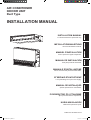
INSTALLATION MANUAL
For authorized service personnel only.
INSTALLATIONSANLEITUNG
Nur für autorisiertes Personal.
MANUEL D'INSTALLATION
Pour le personnel agréé uniquement.
MANUAL DE INSTALACIÓN
Solo para personal autorizado.
MANUALE D'INSTALLAZIONE
Ad uso esclusivo del personale autorizzato.
ΕΓΧΕΙΡΙΔΙΟ ΕΓΚΑΤΑΣΤΑΣΗΣ
Για εξουσιοδοτημένο προσωπικό σέρβις.
MANUAL DE INSTALAÇÃO
Apenas para técnicos autorizados.
РУКОВОДСТВО ПО УСТАНОВКЕ
Для уполномоченного персонала.
KURULUM KILAVUZU
Yetkili servis personeli içindir.
INSTALLATION MANUAL
AIR CONDITIONER
INDOOR UNIT
Duct Type
hcstueDsiaçnarFloñapsEonailatIάkIvηλλEsêugutroP
hsilgnE
eçkrüT
йикссуР
PART NO. 9374815173-04
9374815173-04_IM.indb 1 9/21/2011 1:45:04 PM

En-1
CAUTION!
This mark indicates procedures which, if improperly performed,
might possibly result in personal harm to the user, or damage to
property.
Read carefully all security information before use or install the air conditioner.
Do not attempt to install the air conditioner or a part of the air conditioner by yourself.
This unit must be installed by qualified personnel with a capacity certificate for handling
refrigerant fluids. Refer to regulation and laws in use on installation place.
Th
e installation must be carried out in compliance with regulations in force
in the place
of installation and the installation instructions of the manufacturer.
This unit is part of a set constituting an air conditioner. It must not be installed alone or
with non-authorized by the manufacturer.
Always use a separate power supply line protected by a circuit breaker operating on all
wires with a distance between contact of 3mm for this unit.
The unit must be correctly grounded and the supply line must be equipped with a
differential breaker in order to protect the persons.
The units are not explosion proof and therefore should not be installed in explosive
atmosphere.
Never touch electrical components immediately after the power supply has been turned
off. Electric shock may occur. After turning off the power, always wait 5 minutes before
touching electrical components.
This unit contains no user-serviceable parts. Always consult authorized service
personnel to repairs.
When moving, consult authorized service personnel for disconnection and installation of
the unit.
2. ABOUT THE UNIT
2.1. Precautions for using the R410A refrigerant
WARNING
• Do notintroduceanysubstance other than the prescribed refrigerant into the
refrigeration cycle.
If air enters the refrigeration cycle, the pressure in the refrigeration cycle will become
abnormally high and cause the piping to rupture.
• Ifthereisarefrigerantleakage,makesurethatitdoesnotexceedtheconcentration
limit.
If a refrigerant leakage exceeds the concentration limit, it can lead to accidents such
as oxygen starvation.
• Do nottouch refrigerant thathas leaked fromthe refrigerant pipe connections or
other area. Touching the refrigerant directly can cause frostbite.
• If a refrigerant leakage occurs during operation, immediately vacate the premises
and thoroughly ventilate the area.
Iftherefrigerantcomesincontactwithaame,itproducesatoxicgas.
2.2. Special tool for R410A
WARNING
• To install a unit that uses the R410Arefrigerant, use dedicated toolsand piping
materialsthathavebeenmanufacturedspecicallyforR410Ause.
BecausethepressureoftheR410Arefrigerantisapproximately1.6timeshigherthan
the R22, failure to use dedicated piping material or improper installation can cause
rupture or injury.
Furthermore, it can cause serious accidents such as water leakage, electric shock, or
re.
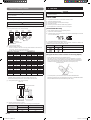
Tool name Contents of change
Gauge manifold
•Pressureishugeandcannotbemeasuredwithaconventional
gauge. To prevent erroneous mixing of other refrigerants, the
diameter of each port has been changed.
It is recommended to use a gauge manifold with a high
pressuredisplayrange–0.1to5.3MPaandalowpressure
displayrange–0.1to3.8MPa.
Charging hose
•Toincreasepressureresistance,thehosematerialandbase
size were changed.
Vacuum pump
• Aconventionalvacuumpumpcanbeusedbyinstallinga
vacuum pump adapter.
Gas leakage
detector
•SpecialgasleakagedetectorforHFCrefrigerantR410A.
1. SAFETY PRECAUTIONS
• BesuretoreadthisManualthoroughlybeforeinstallation.
• ThewarningsandprecautionsindicatedinthisManualcontainimportantinformation
pertaining to your safety. Be sure to observe them.
• HandthisManual,togetherwiththeOperatingManualtothecustomer.
Request the customer to keep them on hand for future use, such as for relocating or
repairing the unit.
WARNING!
This mark indicates procedures which, if improperly performed,
might lead to the death or serious injury of the user.
• Requestyourdealeroraprofessionalinstallertoinstalltheunitinaccordancewith
thisManual.
An improperly installed unit can cause serious accidents such as water leakage,
electricshock,orre.
IftheunitisinstalledindisregardoftheinstructionsintheInstallationManual,itwill
void the manufacturer’s warranty.
• DonotturnONthepoweruntilallworkhasbeencompleted.
Turning ON the power before thework is completed can cause serious accidents
suchaselectricshockorre.
• Ifrefrigerantleakswhileworkisbeingcarriedout,ventilatethearea.
Iftherefrigerantcomesincontactwithaame,itproducesatoxicgas.
• Installationworkmustbeperformedinaccordancewithnationalwiringstandardsby
authorized personnel only.
• ExceptforEMERGENCY, neverturn offmainas wellassub breakerof theindoor
units during operation. It will cause compressor failure as well as water leakage.
First, stop the indoor unit by operating the control unit, converter or external input
device and then cut the breaker.
Makesuretooperatethroughthecontrolunit,converterorexternalinputdevice.
When the breaker is designed, locate it at a place where the users cannot start and
stop in the daily work.
INSTALLATION MANUAL
PARTNO.9374815173-04
INDOORUNIT(DuctType)
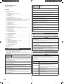
Contents
1. SAFETYPRECAUTIONS ..........................................................................................1
2. ABOUTTHEUNIT
2.1.PrecautionsforusingtheR410Arefrigerant .......................................................1
2.2.SpecialtoolforR410A ........................................................................................1
2.3. Accessories ........................................................................................................2
2.4.Optionalparts .....................................................................................................2
3. INSTALLATIONWORK
3.1.Selectinganinstallationlocation ........................................................................2
3.2A.Installationdimensions(Ceilingconcealedtype) .............................................3
3.2B.
Installationdimensions(Wallmountedtype/Floorstandingconcealedtype) ...3
3.3A.Installationtheunit(Ceilingconcealedtype) ....................................................3
3.3B.Installtheunit(Wallmountedtype/Floorstandingconcealedtype) ................5
4.
PIPEINSTALLATION
4.1.Selectingthepipematerial .................................................................................6
4.2.Piperequirement ................................................................................................7
4.3.Flareconnection(Pipeconnection) ....................................................................7
4.4.Installingheatinsulation .....................................................................................7
5. INSTALLINGDRAINPIPES
5.1A.Installingdrainpipes(Ceilingconcealedtype) .................................................8
5.1B.Installingdrainpipes(Wallmountedtype/Floorstandingconcealedtype) .............8
5.2. Install the drain pipe ...........................................................................................8
6. ELECTRICALWIRING
6.1.Wiringsystemdiagram .....................................................................................11
6.2.Connectioncablepreparation ........................................................................... 11
6.3.Connectionofwiring .........................................................................................11
7. REMOTECONTROLLERSETTING
7.1.Installingtheremotecontroller .........................................................................12
7.2.Settingthedipswitches ....................................................................................12
7.3.Functionsetting ................................................................................................13
7.4.Jumperwiresetting ..........................................................................................14
7.5.Specialinstallationmethods .............................................................................15
8. TESTRUN ...............................................................................................................15
9. OPTIONALPARTS
9.1.Wiredremotecontroller(Simpleremotecontroller) ..........................................16
9.2.Externalinputandexternaloutput ....................................................................16
9.3.Remotesensor(Optionalparts) .......................................................................16
9.4.IRReceiverUnit(Optionalparts) ......................................................................16
9.5.Autolouvergrille(Optionalparts) .....................................................................17
9.6.Optionalpartscablebinding .............................................................................17
10. CUSTOMERGUIDANCE ........................................................................................17
11. ERRORCODES ......................................................................................................18
9374815173-04_IM.indb 1 9/21/2011 1:45:04 PM

En-2
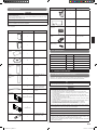
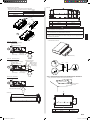
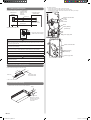
2.3. Accessories
WARNING
• Forinstallationpurposes,besure tousethepartssupplied bythemanufactureror
other prescribed parts.
The use of non-prescribed parts can cause serious accidents such as the unit to fall,
waterleakage,electricshock,orre.
• Thefollowinginstallationpartsarefurnished.Usethemasrequired.
• KeeptheInstallationManualinasafeplaceanddonotdiscardanyotheraccessories
until the installation work has been completed.
Do not discard any accessories needed for installation until the installation work has
been completed.
Name and Shape Q’ty Application
OperatingManual
1
InstallationManual
1
(Thisbook)
Installation
template
1
For positioning the indoor
unit
Washer
8
For installing indoor unit
Coupler
heat insulation
(Large)
1
For indoor side pipe joint
(Largepipe)
Coupler
heat insulation
(Small)
1
For indoor side pipe joint
(Smallpipe)
Binder
Medium
3
For power supply and
transmission and remote
controller cable binding.
Large
4
For fixing the coupler heat
insulation.
Filter(Small)
2
(7000,9000,12000,14000BTU/h)
Filter(Big)
2
(18000BTU/h)
Drain hose
1
For installing drain pipe
VP25(O.D.32,I.D.25)
Name and Shape Q’ty Application
Hoseband
1
For installing drain hose
Drain hose insulation B
1
Insulates the drain hose
Wired Remote
Controller
1
RemoteController
Cable
1
For connecting the
remote controller
Tapping screw
(M4×16mm)
2
For installing the remote
controller
2.4. Optional parts
Parts name Model No. Application
Wired remote controller UTY-RNN*M For air conditioner operation
SimpleRemoteController UTY-RSN*M For air conditioner operation
IRReceiverUnit UTY-LRH*M For the wireless remote controller
Remote sensor unit UTY-XSZX Room temperature sensor
External control set UTD-ECS5A Forcontrolinput/outputport
Auto louver grille UTD-G*S*-W Air outlet grille with auto louver
3. INSTALLATION WORK
3.1. Selecting an installation location
Especially, the installation place is very important for the split type air conditioner
becauseitisverydifculttomovefromplacetoplaceaftertherstinstallation.
WARNING
• Selectinstallationlocationsthatcanproperlysupporttheweightoftheindoor.Install
the units securely so that they do not topple or fall.
CAUTION
• Donotinstalltheunitinthefollowingareas:
• Areawithhighsaltcontent,suchasattheseaside.
It will deteriorate metal parts, causing the parts to fail or the unit to leak water.
• Arealledwithmineraloilorcontainingalargeamountofsplashedoilorsteam,
such as a kitchen.
It will deteriorate plastic parts, causing the parts to fail or the unit to leak water.
• Area that generates substances that adversely affect the equipment, such as
sulfuric gas, chlorine gas, acid, or alkali.
It will cause the copper pipes and brazed joints to corrode, which can cause
refrigerant leakage.
• Areathatcancausecombustiblegastoleak,containssuspendedcarbonbersor
ammabledust,orvolatileinammablessuchaspaintthinnerorgasoline.
Ifgasleaksandsettlesaroundtheunit,itcancauseare.
• Areawhereanimalsmayurinateontheunitorammoniamaybegenerated.
• Do not use the unit for special purposes, such as storing food, raising animals,
growing plants, or preserving precision devices or art objects.
It can degrade the quality of the preserved or stored objects.
• Donotinstallwherethereisthedangerofcombustiblegasleakage.
• Donotinstalltheunitnearasourceofheat,steam,orammablegas.
• Installtheunitwheredrainagedoesnotcauseanytrouble.
• Install the indoor unit, outdoor unit, power supply cable, transmission cable, and
remotecontroller cableat least 1m awayfrom atelevisionor radioreceivers.The
purpose of this is to prevent TV reception interference or radio noise.
(Evenifthey areinstalledmore than1mapart,you couldstillreceive noiseunder
somesignalconditions.)
9374815173-04_IM.indb 2 9/21/2011 1:45:06 PM

En-3
CAUTION
• Ifchildrenunder10yearsoldmayapproachtheunit,takepreventivemeasuresso
that they cannot reach the unit.
• Decide the mounting position with the customer as follows:
(1) Installtheindoorunitinalocationhavingsufcientstrengthtosupporttheweightof
the indoor unit.
(2) Theinletandoutletportsshouldnotbeobstructed;theairshouldbeabletoblowall
over the room.
(3) Leavethespacerequiredtoservicetheairconditioner.
(4) Locatewheretheaircanbedistributedevenlythroughouttheroombytheunit.
(5) Installtheunitwhereconnectiontotheoutdoorunitiseasy.
(6) Installtheunitwheretheconnectionpipecanbeeasilyinstalled.
(7) Installtheunitwherethedrainpipecanbeeasilyinstalled.
(8) Installtheunitwherenoiseandvibrationisnotamplied.
(9) Takeservicing,etc.,intoconsiderationandleavethespaces.Alsoinstalltheunit
wheretheltercanberemoved.
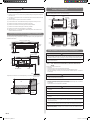
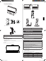
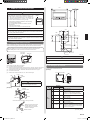
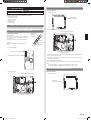
3.2A. Installation dimensions (Ceiling concealed type)
ProvideaServiceaccessforinspectionpurposes.
Do not place any wiring or illumination in the service space, as they will impede service.
Installation Dimensions
Left
side
Stronganddurableceiling
Indoor unit
Right
side
150mm
or more
400mm
or more
Serviceaccess Ceiling
2500mmormore
(Whennoceiling)
Floor
240mmormore
20mmormore
20mmormore
300mmormore
Adjust the wind direction in the room depending on the shape of blow out opening.
Serviceaccess
Unit
Control
box
400mm
or more
100mm
or more
300mm
or more
Servicespace
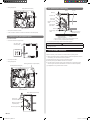
3.2B.
Installation dimensions (Wall mounted type/Floor
standing concealed type)
Thewallmountedtype/oorstandingconcealedtyperequiresatemperature
correctionsetting.Performthisin“7.3.Functionsetting”.
Strongand
durableoor
10mm
or less
Leftside
Leftside
150mm
or more
150mm
or more
150mm
or more
150mm
or more
150mm
or more
150mm
or more
20mm
or more
20mm
or more
20mm
or more
20mm
or more
400mm
or more
400mm
or more
Inlet air
Inlet air
Strongand
durableoor
Strongand
durableoor
10mm
or less
Right side
(PIPEside)
Right side
(PIPEside)
Grille
Duct
Grille
Strongand
durableoor
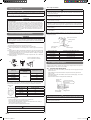
3.3A. Installation the unit (Ceiling concealed type)
WARNING
• Install the air conditioner in a location which can withstanda load do at least 5
times the weight of the main unit and which will not amplify sound or vibration. If the
installation location is not strong enough, the indoor unit may fall and cause injuries.
• If the job is done with thepanel frame only,there is a risk that theunit will come
loose.Pleasetakecare.
3.3A.1. UNIT INSTALLATION EXAMPLE (CEILING CONCEALED
TYPE)
Connectthelocallypurchasedduct.
(1)Inletside
• Connecttheducttothelocallypurchasedinletange.
• Connecttheangetothebodywiththelocallypurchasedtappingscrews.
• Windtheinletangeconnectingtotheductwiththealuminumtapeetc.toavoidthe
air discharge.
CAUTION
• Whentheductisconnectedtoinletside,removecontainedlterandsurelyattach
locallypurchasedlteratinletopening.
(2)Outletside
• Connecttheductwithadjustinginsideofoutletange.
• Windtheoutletangeconnectingtotheductwiththealuminumtapeetc.toavoidthe
air discharge.
• Insulatetheducttoavoidthedewcondensation.
CAUTION
• Check that duct work doesnot exceed the rangeof externalstaticpressure of
equipment.
• Makesuretoinsulateductstoavoidthedewcondensation.
• Makesuretoinsulatebetweenductsandwallsifmetalductsareused.
• Pleaseexplainhandlingandwashingmethodsoflocallypurchasedmaterialstothe
customer.
• Topreventpeoplefromtouchingthepartsinsidetheunit,besuretoinstallgrilleson
the inlet and outlet ports. The grilles must be designed in such a way that cannot be
removed without tools.
• Whenconnectingtheducttotheoutletportoftheindoorunit,besuretoinsulatethe
outlet port and the installation screws to prevent water from leaking around the port.
AR07/09/12/14/18Model
• Setthestatic pressure outside the unit to 90 Pa or less (the allowable range is
between0and90Pa).
9374815173-04_IM.indb 3 9/21/2011 1:45:07 PM

En-4
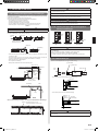
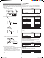
Replace the cover as follows.
• Removethescrews,andthenremovecoverandfanguard.
• Installthecoverwiththescrewsasshownintheillustrationbelow.
Model
Screw
M5
7000,9000,12000,14000BTU/h 9
18000BTU/h 11
screw(M5)
Cover
Fan guard
SideInlet-SideOutlet
Insulationmaterial(Fieldsupply)
Aluminum tape
Flange(Fieldsupply)
Air
Duct
(Fieldsupply)
Air
Intake grille
(Fieldsupply)
SideInlet-SideOutlet(Duct)
Insulationmaterial(Fieldsupply)
Aluminum tape
Aluminum tape
Tapping screw for
angeconnection
(M5x10mm/
Fieldsupply)
Flange(Fieldsupply)
Flange(Fieldsupply)
Air
Duct
(Fieldsupply)
Air
Intake grille
(Fieldsupply)
BottomInlet-SideOutlet
Duct(Fieldsupply)
Intakegrille(Fieldsupply)
Air
Air
Outletside
Inlet side
7000,9000,12000,14000BTU/h 18000BTU/h
A 650mm 850mm
B P200×2=400mm P200×3=600mm
CAUTION
• Be sure to install the air inlet grille and the air outlet grille for aircirculation. The
correct temperature cannot be detected.
• Grills mustbexed so that man cannot touch indoor unit fan and exchanger, and
cannot be removed by only hand operation without tool.
• Besuretoinstalltheairlterintheairinlet.
If the air fi lter is not installed, the heat exchanger may be clogged and its
performance may decrease.
3.3A.2. INSTALL THE FILTERS
• Installthelterstotheunit.
Filter(Accessories)
Unit
Filter
3.3A.3.
DRILLING HOLES FOR BOLTS AND INSTALLING THE BOLTS
• Usingtheinstallationtemplate,drillholesforbolts(4holes).
Drilling position
for bolts
Installation template
A
Air
377mm
7000,9000,12000,14000BTU/h 18000BTU/h
A 734mm 934mm
9374815173-04_IM.indb 4 9/21/2011 1:45:12 PM

En-5
3.3B. Install the unit (Wall mounted type/ Floor standing
concealed type)
WARNING
• Install the air conditioner in a location which can withstand a load doat least 5
times the weight of the main unit and which will not amplify sound or vibration. If the
installation location is not strong enough, the indoor unit may fall and cause injuries.
• If the job is done with the panel frame only, there is a risk that the unitwill come
loose.Pleasetakecare.
3.3B.1. UNIT INSTALLATION EXAMPLE
(Wall mounted type/Floor standing concealed type)
Connectthelocallypurchasedduct.
(1)Inletside
• Connecttheducttothelocallypurchasedinletange.
• Connecttheangetothebodywiththelocallypurchasedtappingscrews.
• Windtheinletangeconnectingtotheductwiththealuminumtapeetc.toavoidthe
air leakage.
CAUTION
• Whentheductisconnectedtoinletside,removecontainedlterandsurelyattach
locallypurchasedlteratinletopening.
(2)Outletside
• Connecttheductwithadjustinginsideofoutletange.
• Windtheoutletangeconnectingtotheductwiththealuminumtapeetc.toavoidthe
air discharge.
• Insulatetheducttoavoidthedewcondensation.
CAUTION
• Check that duct work doesnot exceed the rangeof externalstaticpressure of
equipment.
• Makesuretoinsulateductstoavoidthedewcondensation.
• Makesuretoinsulatebetweenductsandwallsifmetalductsareused.
• Pleaseexplainhandlingandwashingmethodsoflocallypurchasedmaterialstothe
customer.
• Topreventpeoplefromtouchingthepartsinsidetheunit,besuretoinstallgrilleson
the inlet and outlet ports. The grilles must be designed in such a way that cannot be
removed without tools.
• Whenconnectingtheducttotheoutletportoftheindoorunit,besuretoinsulatethe
outlet port and the installation screws to prevent water from leaking around the port.
• Set the static pressure outside the unit to 90Pa or less (the allowable range is
between0and90Pa).
• Removethescrews,andthenremovecoverandfanguard.
• Installthecoverwiththescrewsasshownintheillustrationbelow.
Model
Screw
M5
7000,9000,12000,14000BTU/h 9
18000BTU/h 11
Cover
Fan guard
screw(M5)
3.3A.4. FIX THE UNIT
(1)Hangtheunit
Hangerbolt
Nut A
(Fieldsupply)
Nut B
(Fieldsupply)
Washer
(Accessories)
Hanger
Hangerbolt
Nut A
(Fieldsupply)
Washer
(Accessories)
Nut B
(Fieldsupply)
Unit
Hanger
20mm
length
Cover
*:It might become difficult to open and shut the Cover /control box cover when the
lengthexceeds20mm.
(2)Leveling
Base horizontal direction leveling on top of the unit.
Ceiling
Level
OK
NOGOOD
10mmorless
Level
Air
OK NOGOOD
10mmorless
CAUTION
• Leaveaspaceof100mmormorebetweentheinletportandtheceiling.
• FastentheunitsecurelywithSpecialnutsAandB.
9374815173-04_IM.indb 5 9/21/2011 1:45:17 PM

En-6
3.3B.2. INSTALL THE FILTER
• Installthelters(Accessories)totheunit.
Filter
Unit
Filter
Replace drain cap
CAUTION
• Set“7.4.JumperwiresettingofDrainagefunctionsetting(JM1)”.
• Drain pump cannot be used if it is installed in wallmounted type/floor standing
concealed type.
3.3B.3. INSTALLING THE UNIT
(1)Fixingmethodoftheunit
• Topreventoverturning,xtheunittotheoororthewall.
• Toavoidthevibrationoftheunit,insertthespacerbetweentheunitandtheoororthe
wall,andxit.
(2)Leveling
Base horizontal direction leveling on top of the unit.
Level
10mmorless
NOGOOD
OK
Level
NOGOODOK
10mmorless
CAUTION
•
FastentheunitsecurelywithSpecialnutsAandB.
4.
PIPE INSTALLATION
CAUTION
• Be careful that foreign matter (oil, water, etc.) does not enter the piping with
refrigerantR410Amodels.Also,whenstoringthepiping,securelysealtheopenings
by pinching, taping, etc.
• While brazing the pipes, be sure to purge with dry nitrogen gas.
4.1. Selecting the pipe material
CAUTION
• Do not use existing pipes.
• Use pipes that have clean external and internal sides without any contamination
which may cause trouble during use, such as sulfur, oxide, dust, cutting waste, oil, or
water.
• It is necessary to use seamless copper pipes.
Material:Phosphordeoxidizedseamlesscopperpipes
Itisdesirablethattheamountofresidualoilislessthan40mg/10m.
• Do not use copper pipes that have a collapsed, deformed, or discolored portion
(especiallyontheinteriorsurface).Otherwise,theexpansionvalveorcapillarytube
may become blocked with contaminants.
• Improperpipeselectionwilldegradeperformance.AsanairconditionerusingR410A
incurs pressure higher than when using conventional refrigerant, it is necessary to
choose adequate materials.
•
ThicknessesofcopperpipesusedwithR410Aareasshowninthetable.
•
Never use copper pipes thinner than those indicated in the table even if they are
available on the market.
Thicknesses of Annealed Copper Pipes (R410A)
Pipe outside diameter [mm (in.)] Thickness [mm]
6.35(1/4) 0.80
9.52(3/8) 0.80
12.70(1/2) 0.80
15.88(5/8) 1.00
19.05(3/4) 1.20
9374815173-04_IM.indb 6 9/21/2011 1:45:20 PM

En-7
4.2. Pipe requirement
CAUTION
• Referto the Installation Manualof the outdoor unitfor description of thelength of
connecting pipe or for difference of its elevation.
• Usepipewithwater-resistantheatinsulation.
CAUTION
• Install heat insulation around both the gas and liquid pipes. Failure to do so may
cause water leaks.
Useheatinsulationwithheatresistanceabove120°C.(Reversecyclemodelonly)
In addition, if the humidity level at the installation location of the refrigerant piping is
expectedtoexceed70%,installheatinsulationaroundtherefrigerantpiping.Ifthe
expectedhumiditylevelis70-80%,useheatinsulationthatis15mmorthickerand
iftheexpectedhumidityexceeds80%,useheatinsulationthatis20mmorthicker.
Ifheatinsulationisusedthatisnotasthickasspecied,condensationmayformon
the surface of the insulation. In addition, use heat insulation with heat conductivity of
0.045W/(m·K)orless(at20°C).
4.3. Flare connection (Pipe connection)
WARNING
• Tightenthe are nuts with a torque wrench using the specied tighteningmethod.
Otherwise,thearenutscouldbreakafteraprolongedperiod,causingrefrigerantto
leakandgenerateahazardousgasiftherefrigerantcomesintocontactwithaame.
4.3.1. Flaring
• UsespecialpipecutterandaretoolexclusiveforR410A.
(1)
Cuttheconnectionpipetothenecessarylengthwithapipecutter.
(2)
Hold the pipe downward so that cuttings will not enter thepipe and remove any
burrs.
(3)
Insertthearenut(alwaysusethearenutattachedtotheindoorandoutdoorunits
respectively)ontothepipeandperformtheareprocessingwithaaretool.Use
thespecialR410Aaretool,orthe conventionalaretool. Leakageofrefrigerant
mayresultifotherarenutsareused.
(4)
Protectthepipesbypinchingthemorwithtapetopreventdust,dirt,orwaterfrom
entering the pipes.
/
Die
Pipe
A
B
Checkif[L]isareduniformly
and is not cracked or scratched.
Pipe outside diameter
[mm (in.)]
Dimension A [mm]
Dimension B
-
0
0.4
[mm]
Flare tool for R410A,
clutch type
6.35(1/4)
0to0.5
9.1
9.52(3/8) 13.2
12.70(1/2) 16.6
15.88(5/8) 19.7
19.05(3/4) 24.0
Whenusing conventional are tools to are R410Apipes, the dimensionAshould be
approximately0.5mmmorethanindicatedinthetable(foraringwithR410Aaretools)
toachievethespeciedaring.UseathicknessgaugetomeasurethedimensionA.
Width across
ats
Pipe outside
diameter [mm (in.)]
Width across flats
of Flare nut [mm]
6.35(1/4) 17
9.52(3/8) 22
12.70(1/2) 26
15.88(5/8) 29
19.05(3/4) 36
4.3.2. Bending pipes
•
If pipes are shaped by hand, be careful not to collapse them.
•
Donotbendthepipesinananglemorethan90°.
•
When pipes are repeatedly bend or stretched, the material will harden, making it
difculttobendorstretchthemanymore.
•
Do not bend or stretch the pipes more than 3 times.
CAUTION
• To prevent breaking of the pipe, avoid sharp bends.
• If the pipe is bent repeatedly at the same place, it will break.
4.3.3. Pipe connection
CAUTION
• Be sure to install the pipe against the port on the indoor unit correctly. If the centering
isimproper,thearenutcannottightensmoothly.Ifthearenutisforcedtoturn,the
threads will be damaged.
• Do not removethe flare nut fromthe indoor unit pipe until immediatelybefore
connecting the connection pipe.
• Holdthetorquewrenchatitsgrip,keepingitatarightanglewiththepipe,inorderto
tightenthearenutcorrectly.
• Tightentheare nutswith a torquewrench using thespecied tightening method.
Otherwise,thearenutscouldbreakafteraprolongedperiod,causingrefrigerantto
leakandgenerateahazardousgasiftherefrigerantcomesintocontactwithaame.
• Connectthepipingsothatthecontrolboxcovercaneasilyberemovedforservicing
when necessary.
• Inordertopreventwaterfromleakingintothecontrolbox,makesurethatthepiping
is well insulated.
Whenthearenutistightenedproperlybyyourhand,holdthebodysidecouplingwith
aseparatespanner,thentightenwithatorquewrench.(Seethetablebelowfortheare
nuttighteningtorques.)
Tighten with 2 wrenches.
Holdingwrench
Flare nut
Connectionpipe
Torque wrench
Indoor unit pipe
(Bodyside)
Flare nut [mm (in.)] Tightening torque [N·m (kgf·cm)]
6.35(1/4)dia. 16to18(160to180)
9.52(3/8)dia. 32to42(320to420)
12.70(1/2)dia. 49to61(490to610)
15.88(5/8)dia. 63to75(630to750)
19.05(3/4)dia. 90to110(900to1,100)
4.4. Installing heat insulation
Install the heat insulation material after performing a refrigerant leak check (see the
InstallationManualfortheoutdoorunitfordetails).
4.4.1. COUPLER HEAT INSULATION
• Insulatewiththecouplerheatinsulation(Accessories)aroundthegaspipeandliquid
pipe at indoor unit.
• Afterinstallingthecouplerheatinsulation,wrapbothendswithvinyltapesothat
there is no gap.
• Afterafxingthecouplerheatinsulation,secureitwith2binders(large),oneoneach
end of the insulation.
• Makesurethatthebindersoverlaptheheatinsulationpipe.
Couplerheat
insulation
(Accessories)
Coverthisportionwith
heat insulation.
Binder(Large)
(Accessories)
Heatinsulation
CAUTION
• Afterchecking for gas leaks (refer to the Installation Manual of the outdoor unit),
perform this section.
• Installheatinsulationaroundboththelarge(gas)andsmall(liquid)pipes.Failureto
do so may cause water leaks.
9374815173-04_IM.indb 7 9/21/2011 1:45:21 PM

En-8
5. INSTALLING DRAIN PIPES
5.1A. Installing drain pipes (Ceiling concealed type)
Usegeneralhardpolyvinylchloridepipeandconnectitwithadhesive(polyvinylchloride)
so that there is no leakage.
Always heat insulate the indoor side of the drain hose.
Useadrainpipethatmatchesthesizeofthedrainhose(TableA).
• Donotperformarise,trapandairbleeding.
• Provideadownwardgradient(1/100ormore).
• Providesupportswhenlongpipesareinstalled.
• Useaninsulationmaterialasneeded,topreventthepipesfromfreezing.
• Installthepipesinawaythatallowsfortheremovalofthecontrolbox.
Table A
O.D.
Drain pipe 32mm(VP25)
CEILINGCONCEALEDTYPE(UseDrainPump)
Outletair
ow
Arrange the drain hose
lower than this port.
Drain hose
Trap
OK
NOGOODDrain cap NOGOOD
Rise
Air bleeding
Supporter
NOGOOD
1.5to2m
OK
• Installthedrainpipewithdownwardgradient(1/50to1/100)andsotherearenorises
or traps in the pipe.
• Use general hard polyvinyl chloride pipe (VP25) [outside diameter 32 mm] and
connectitwithadhesive(polyvinylchloride)sothatthereisnoleakage.
• Whenthepipeislong.Installsupports.
• Donotperformairbleeding.
• Alwaysheatinsulatetheindoorsideofthedrainpipe.
VP25
[O.D32mm
ormore]
Horizontalor
upward gradient
Supporter
Gapof1.5-2m
Locallyarrangedpipe
Max.
300mm
700mmorless
RiseAir bleeding
BAD
Trap
Observe the following procedures to construct centralized drain pipe ttings
.
VP30ormore[O.D38mmormore]
Downwardgradient1/100ormore
700mmorless
WARNING
• Do not insert the drain piping into the sewer where sulfurous gas occurs. (Heat
exchangeerosionmayoccur)
• Insulatethepartsproperlysothatwaterwillnotdripfromtheconnectionparts.
• Check for proper drainage afterthe construction by using the visible portion of
transparentdrainportandthedrainpipingnaloutletonthebody.
CAUTION
• Donotapplyadhesiveagentonthedrainportofthebody.
(Usetheattacheddrainhoseandconnectthedrainpiping)
5.1B. Installing drain pipes (Wall mounted type/Floor
standing concealed type)
NOGOOD
OK
NOGOOD
RiseTrap
Drain
cap
CAUTION
• Drain pump cannot be usedif it is installed in wall mounted type/floor standing
concealed type.
• Set“7.4.JumperwiresettingofDrainagefunctionsetting(JM1)”.
• Besuretoconnectthepipesfordrainagewithoutleakage.
• Toavoidcondensationanddripping,alwaysinsulatetheindoordrainpipe.
5.2. Install the drain pipe
(1)BesuretousesuppliedDrainhose
1
andHoseband
2
2
Hoseband
Drain
hole
1
Drain hose
HardPVCside
• When drain pump is used.(Ceilingconcealedtypeonly)
Hoseband
4mmorless
20mm
• When drain pump is not used.(Naturaldrainage)
Jointpipe
(Fieldsupply)
Drainpipe(VP25)
(Fieldsupply)
Applying
area of
adhesive
4mmorless
CAUTION
• Whendrainpumpisnotused,donotconnecttheaccessorydrainhoseandsoftPVC
hose directly
.
9374815173-04_IM.indb 8 9/21/2011 1:45:22 PM

En-9
(2)
Be sure to insert Drain hose
1
to the very end of the Drain pan of the unit with no space
.
Applying
area of
adhesive
Jointpipe
(Fieldsupply)
Drainpipe(VP25)
(Fieldsupply)
4mmorless
2
Hoseband
1
Drain hose
FastentheHoseband
2
at the position where
vertical against ground.
TheHoseband
2
must be positioned at the right
side of the Drain hose
1
asinthegure.
CAUTION
• DonotconnecttotheDrainholewithadhesive.Usingadhesivemaycausedamage
and water leaks.
(3) AfterinstallingtheDrainhose
1
, check if the drainage is smooth.
• When drain pump is not used.(Naturaldrainage)
Downward
gradient
2.5-5.0mm
CAUTION
• TopreventexcessiveforceonDrainhose
1
,avoidbendsortwists.(Tobendortwist
maycausewaterleaks.)
(4) Aftercheckingfordrainage,attachtheDrainhoseinsulationB
3
to insulate, following
theinstructionsasinthegures.
To avoid space with Drain hose
1
andHoseband
2
,pressrmlytheDrainhose
insulation B
3
.
• When drain pump is used.(Ceilingconcealedtypeonly)
3
Drain hose
insulation B
Ensure there is
no space.
• When drain pump is not used.(Naturaldrainage)
3
Drain hose
insulation B
Ensure there is
no space.
• STEP1~STEP3
Butt the insulation against the unit.
STEP1
Unit
Slit
Pressrmly
Pressrmly
STEP2
Slit
Pressrmly
Roll the
insulation
over the joint.
STEP3
Pressrmly
Pressrmly
Slit
• FINISH
Checkthatthereisnogapbetweentheunitandthedrainhoseinsulation.
• When drain pump is used.(Ceilingconcealedtypeonly)
Do not cover the
panel window.
• When drain pump is not used.(Naturaldrainage)
Do not cover the
control box cover.
Note: Check for drainage
Pourabout1literofwaterfromthepositionshowninthediagramorfromtheairow
outlettothecondensatetray.Checkforanyabnormalitiessuchasstrangenoisesand
whether the drain pump functions normally.
CAUTION
•Makesurethedrainwaterisproperlydrained.
9374815173-04_IM.indb 9 9/21/2011 1:45:23 PM

En-10
6. ELECTRICAL WIRING
Cable Cable size (mm
2
) Type Remarks
Connectioncable 1.5 Type60245IEC57 3Cable+Ground,1φ230V
Max.CableLength:Limitvoltagedroptolessthan2%.Increasecablegaugeifvoltagedropis
2%ormore.
WARNING
• Electrical work mustbe performed in accordance with this Manual by a person
certiedunderthenationalorregionalregulations.Besuretouseadedicatedcircuit
for the unit.
Aninsufcientpowersupplycircuitorimproperlyperformedelectricalworkcancause
seriousaccidentssuchaselectricshockorre.
• Beforestartingwork, checkthat powerisnot beingsupplied totheindoor unitand
outdoor unit.
• Forwiring, use the prescribed typeof cables, connect them securely,making sure
that there are no external forces of the cables applied to the terminal connections.
Improperly connected or secured cables can cause serious accidents such as
overheatingtheterminals,electricshock,orre.
• Securelyinstalltheelectricalboxcoverontheunit.
An improperly installed electrical box cover can cause serious accidents such as
electricshockorrethroughexposuretodustorwater.
• Installsleevesintoanyholesmadeinthewallsforwiring.Otherwise,ashortcircuit
could result.
• Use the included connection cables and power cables or ones specified by the
manufacturer. Improper connections, insufficient insulation, or exceeding the
allowablecurrentcancauseelectricshockorre.
• Donotmodifythepowercables,useextensioncables,oruseanybranchesinthe
wiring. Improper connections, insufficient insulation, or exceeding the allowable
currentcancauseelectricshockorre.
• Match the terminal blocknumbers and connection cable colors with those of the
outdoor unit or branch box. Erroneous wiring may cause burning of the electric parts.
• Securelyconnecttheconnectioncablestotheterminalboard.Inaddition,securethe
cables with wiring holders. Improper connections, either in the wiring or at the ends
ofthewiring,cancauseamalfunction,electricshock,orre.
• Alwaysfastentheoutsidecoveringoftheconnectioncablewiththecableclamp.(If
theinsulatorischafed,electricleakagemayoccur.)
• Installaearthleakagebreaker.Inaddition,installtheearthleakagebreakersothat
theentireACmainpowersupplyiscutoffatthesametime.Otherwise,electricshock
orrecouldresult.
• Always connect the earth cable.
Improper grounding work can cause electric shocks.
• Install the remote controller cables so as not to be direct touched with your hand.
• Performwiringworkinaccordancewithstandardssothattheairconditionercanbe
operated safely and positively.
• Connecttheconnectioncablermlytotheterminalboard.Imperfectinstallationmay
causeare.
CAUTION
• Groundtheunit.
Do not connect the earth cable to a gas pipe, water pipe, lightning rod, or a telephone
earth cable.
Improper grounding may cause electric shock.
• Do not connect powersupply cables to the transmissionor remotecontroller
terminals, as this will damage the product.
• Neverbundlethepowersupplycableandtransmissioncable,remotecontrollercable
together.
Separatethesecableby50mmormore.
Bundling these cables together will cause miss operation or breakdown.
• WhenhandlingPCB,staticelectricitychargedinthebodymaycausemalfunctionof
thePCB.Followthecautionsbelow:
• Establishagroundfortheindoorandoutdoorunitsandperipheraldevices.
• Cutpower(breaker)off.
• Touch metal part of the indoor and outdoor units for more than 10 seconds to
discharge static electricity charged in the body.
• DonottouchterminalsofpartsandpatternsimplementedonPCB.
(1) Useringterminalswithinsulatingsleevesasshowninthegurebelowtoconnectto
the terminal block.
(2) Securelyclamptheringterminalstothecablesusinganappropriatetoolsothatthe
cables do not come loose.
(3) Usethespeciedcables,connectthemsecurely,andfastenthemsothatthereisno
stress placed on the terminals.
(4) Useanappropriatescrewdrivertotightentheterminalscrews.
Do not use a screwdriver that is too small, otherwise, the screw heads may be
damaged and prevent the screws from being properly tightened.
(5) Donottightentheterminalscrewstoomuch,otherwise,thescrewsmaybreak.
(6) Seethetablefortheterminalscrewtighteningtorques.
(7) Pleasedonotx2powersupplycableswith1screw.
Strip10mm
Sleeve
Screwwithspe-
cial washer
Screwwith
special washer
Ring terminal
Cable
Cable
Terminal block
Ring terminal
Ring
terminal
WARNING
• Useringterminalsandtightentheterminalscrewstothespeciedtorques,otherwise,
abnormal overheating may be produced and possibly cause heavy damage inside
the unit.
Tightening torque
M4screw
1.2to1.8N·m
(12to18kgf·cm)
9374815173-04_IM.indb 10 9/21/2011 1:45:23 PM

En-11
6.1. Wiring system diagram
ConnectioncabletooutdoorunitorBRANCHBOX
INDOORUNIT
OUTDOORUNITor
BRANCHBOX
TERMINAL
Type60245IEC57
Cablesize1.5mm
2
(Inter-unit)
Powerlines
Groundingline
Powerline
Controlline
Pleaseconnectitto
thespeciedterminal.
Wired remote controller cable
*Groundtheremotecontroller
(Pleaseconnectitwhennecessary.)
Red
White
Black
Indoor
unit side
CAUTION
Tighten the indoor unit connection cable and power supply indoor and outdoor unit,
branch box terminal board connections rmly with the terminal board screws.Faulty
connectionmaycauseare.
If the indoor unit connection cable and power supply are wired incorrectly, the air
conditioner may be damaged.
Connect the indoor unit connection cable by matching the numbers of the outdoor,
branch box and indoor units terminal board numbers as shown in terminal label.
Earth both the indoor and outdoor, branch box units by attaching a earth cable.
Unitshallbegroundedincompliancewiththeapplicablelocalandnationalcables.
CAUTION
Besuretorefertotheabovediagramfordocorrecteldwiring.Wrongwiringcauses
malfunction of the unit.
Checklocalelectricalrulesandalsoanyspecicwiringinstructionsorlimitation.
6.2. Connection cable preparation
Keep the earth wire longer than the other wires.
Powersupplycable
or connection cable
20mm
30mmormore
Earth wire
•Usea4-corewirecable.
6.3. Connection of wiring
(1) Removethecontrolboxcoverfromthecontrolbox.
Screw
Controlboxcover
Removethe4screws
and remove the control
box cover from the
control box.
(2) Cableconnection
• Connect the connection cable to the terminal board.
• Connecttheremotecontrollercabletotheterminalboard.
• Fixtheremotecontrollercabletothecontrolboxcoverwithanylonclamp.
Remote controller cable
1:Red
2:White
3:Black
Earth
Binder(Medium)
(Accessories)
Powersupplycable
Binder(Medium)
(Accessories)
Remote controller cable
Powersupplycable
9374815173-04_IM.indb 11 9/21/2011 1:45:24 PM

En-12
.
7. REMOTE CONTROLLER SETTING
CAUTION
When detecting the room temperature using the remote con-
troller, please set up the remote controller according to the
following conditions. If the remote controller is not located prop-
erly, the correct room temperature will not be detected, and
thusabnormalconditions like“not cooled”or“not heated”will
occur even if the air-conditioner is running normally.
• Locatewhereanaveragetemperaturefortheroombeing
air conditioned will be sensed.
• Donotlocatedirectlyexposedtotheoutletairfromthe
air-conditioner.
• Locateoutofdirectsunlight.
• Locateawayfromtheinuenceofotherheatsources.
DonottouchtheremotecontrollerPCboardandPCboardpartsdirectlywithyourhands
.
Do not wire the remote controller cable together with or parallel to the connection ca-
bles,andpowersupplycableofthe INDOORUNITandOUTDOORUNIT,BRANCH
BOX.Itmaycauseerroneousoperation.
When installing the bus wire near a source of electromagnetic waves, use shielded wire
.
DonotsettheDIPswitches,eitherontheairconditionerortheremotecontroller,inany
way other than indicated in this manual that is supplied with the air conditioner. Doing
so may result in improper operation.
7.1. Installing the remote controller
Opentheoperationpanelonthefrontoftheremotecontroller,removethe2screwsindi-
catedinthefollowinggure,andthenremovethefrontcaseoftheremotecontroller.
When installing the remote controller, remove the connector from the front case. The
wires may break if the connector is not removed and the front case hangs down.
When installing the front case, connect the connector to the front case.
Screws
SET BACK
Front case
(backside)
Rear case
Connector
When remote controller cable is concealed
(1) Concealtheremotecontrollercable.
(2) Passtheremotecontrollercablethroughtheholeintherearcaseandconnectthe
remotecontrollercabletotheremotecontrollerterminalboardspeciedingure.
(3) Clamptheremotecontrollercablesheathwiththebinderasshowningure.
(4) Cutofftheexcessbinder.
(5) Installtherearcasetothewall,box,etc.,with2screwsgure.
Binder
(Small)
1.Red
2. White
3. Black
CAUTION
When connecting the remote controller
wires, do not overtighten the screws.
Hole
[Example]
Remote
controller cable
Box
Screws
Connector
Rear case
Groundtheremotecontrollerifithasagroundwire.
Wrap the connector and remote
controller wires with vinyl tape
or some other type of insulation
asshowninthegure.
Remote controller
Temperature
sensor
30
120
17
120
45.3
33.5
Hole
15.3
23
8
4.5
4.5
4.5 12.5
Hole×3
Hole×2
83.5
63.5
6
Unit:mm
CAUTION
Install the remote controller wires so as not to be direct touched with your hand.
Donot touchthe remote controllerPC boardand PC boardparts directly withyour
hands.
7.2. Setting the dip switches
SettheremotecontrollerDIPswitches.
[Example]
ON
ON
OFF
1
2
3
4
5
6
DIPswitch1
Frontcase(backside)
NO.
SW state
Detail
OFF ON
DIP-
switch 1
1
★
Cannotbeused.
(Donotchange)
2
★
Dual remote controller setting
*Referto2.DUALREMOTECONTROL-
LERSin7.5.SpecialInstallationMethods.
3
★
Cannotbeused.
(Donotchange)
4
★
Cannotbeused.
(Donotchange)
5
★
Cannotbeused.
(Donotchange)
6
★
Invalidity Validity
Memorybackupsetting
*SettoON tousebatteries forthememory
backup. If batteries are not used, all of the
settings stored in memory will be deleted if
there is a power failure.
(
★
Factorysetting)
9374815173-04_IM.indb 12 9/21/2011 1:45:25 PM

En-13
7.3. Function setting
This procedure changes the function settings used to control the indoor unit according to
the installation conditions. Incorrect settings can cause the indoor unit to malfunction. This
procedure should be performed by authorized installation or service personnel only.
Performthe“FUNCTIONSETTING”accordingtotheinstallationconditionsusingtheremote
controller.(Refertotheindoorunitinstallationmanualfordetailsonthefunctionnumbers
andsettingvalues.)
(1) PresstheSETTEMP.buttons(
)( )andFANbuttonsimultaneouslyformorethan
5 seconds to enter the function setting mode.
SU
MO
TU
WE
TH FR
SA
(2) PresstheSETBACKbuttontoselecttheindoorunitnumber.
SU
MO
TU
WE
TH FR
SA
UnitnumberofINDOORUNIT
SETBACK
(3) PresstheSETTIME( )buttonstoselectthefunctionnumber.
Function number
SU
MO
TU
WE
TH FR
SA
(4) PresstheSETTEMP.buttons( )( )toselectthesettingvalue.
Thedisplayashesasshowntotherightduringsettingvalueselection.
Settingvalue
SU
MO
TU
WE
TH FR
SA
(5) PresstheTIMERSETbuttontoconrmthesetting.
PresstheTIMERSETbuttonforafewsecondsuntilthesettingvaluestopsashing.
Ifthesettingvaluedisplaychangesorif“--”isdisplayedwhentheashingstops,the
setting value has not been set correctly.
(Aninvalidsettingvaluemayhavebeenselectedfortheindoorunit.)
(6) Repeatsteps2to5toperformadditionalsettings.
PresstheSETTEMP.buttons(
)( )andFANbuttonsimultaneouslyagainfor
more than 5 seconds to cancel the function setting mode. In addition, the func-
tionsettingmodewillbeautomaticallycanceledafter1minuteifnooperationis
performed.
(7) AftercompletingtheFUNCTIONSETTING,besuretoturnoffthepowerandturniton
again.
• Function Details
(1) Filter Sign
Theindoorunithasasigntoinformtheuserthatitistimetocleanthelter.Selectthe
timesettingfortheltersigndisplayintervalinthetablebelowaccordingtotheamount
ofdustordebrisintheroom.Ifyoudonotwishtheltersigntobedisplayed,selectthe
settingvaluefor“Noindication”.
(♦...Factorysetting)
Setting description
Function
number
Setting value
Standard(400hours)
11
00
Longinterval(1000hours) 01
Shortinterval(200hours) 02
♦
No indication 03
(2) Static pressure
Selectappropriatestaticpressureaccordingtotheinstallationconditions.
(♦...Factorysetting
)
Setting description
Function
number
Setting value
0Pa
26
00
10Pa 01
20Pa 02
30Pa 03
40Pa 04
50Pa 05
60Pa 06
70Pa 07
80Pa 08
90Pa 09
♦25Pa[Standard] 31
Rangeofstaticpressureisdifferentfrom1modeltoother.
Range of static pressure 0to90Pa
(3) Cooling room temperature correction
Depending on the installed environment, the room temperature sensor may require a
correction.
The settings may be selected as shown in the table below.
(♦...Factorysetting)
Setting description
Function
number
Setting value
♦
Standard
30
00
Slightlylowercontrol 01
Lowercontrol 02
Warmer control 03
Whenusingoorconsoleinstallation,changethesettingvalueto“01”.
(4) Heating room temperature correction
Depending on the installed environment, the room temperature sensor
may require a
correction.
The settings may be changed as shown in the table below.
(♦...Factorysetting)
Setting description
Function
number
Setting value
♦
Standard
31
00
Lowercontrol 01
Slightlywarmercontrol 02
Warmer control 03
Whenusingoorconsoleinstallation,changethesettingvalueto“01”.
(5) Auto restart
Enable or disable automatic system restart after a power outage.
(♦...Factorysetting)
Setting description
Function
number
Setting value
♦
Yes
40
00
No 01
9374815173-04_IM.indb 13 9/21/2011 1:45:25 PM

En-14
*Autorestartisanemergencyfunctionsuchasforpowerfailureetc.Donotstartandstop
the indoor unit by this function in normal operation. Be sure to operate by the control unit,
or external input device.
(6) Indoor room temperature sensor switching function
(OnlyforWiredremotecontroller)
The following settings are needed when using the Wired remote controller temperature
sensor.
(♦...Factorysetting)
Setting description
Function
number
Setting value
♦
No
42
00
Yes 01
*Ifsettingvalueis“00”:
Room temperature is controlled by the indoor unit temperature sensor.
*Ifsettingvalueis“01”:
Room temperature is controlled by either indoor unit temperature sensor or remote
controller unit sensor.
(7) Wireless remote controller signal code
ChangetheindoorunitSignalCode,dependingonthewirelessremotecontrollers.
(♦...Factorysetting)
Setting description
Function
number
Setting value
♦
A
44
00
B 01
C 02
D 03
(8) External input control
“Operation/Stop”modeor“Forcedstop”modecanbeselected.
(♦...Factorysetting)
Setting description
Function
number
Setting value
♦
Operation/Stopmode
46
00
(Settingforbidden) 01
Forced stop mode 02
Setting record
•
Record any changes to the settings in the following table.
Setting Setting Value
(1)Filtersign
(2)Staticpressure
(3)Coolingroomtemperaturecorrection
(4)Heatingroomtemperaturecorrection
(5)Autorestart
(6)Indoorroomtemperaturesensorswitchingfunc-
tion
(7)Wirelessremotecontrollersignalcode
(8)Externalinputcontrol
After completing the FUNCTION SETTING, be sure to turn off the power and turn it on
again.
SETTING THE ROOM TEMPERATURE DETECTION
LOCATION
The detection location of the room temperature can be selected from the following 2 examples.
Choosethedetectionlocationthatisbestfortheinstallationlocation.
A. Indoor unit setting (factory setting)
The room temperature is detected by the indoor unit temperature sensor
.
(1) WhentheTHERMOSENSORbuttonispressed,thelockdisplayashesbecausethe
function is locked at the factory.
A
Indoor unit
B. Indoor unit/remote controller setting (room tempera-
ture sensor selection)
The temperature sensor of the indoor unit or the remote controller can be used to detect
the room temperature.
(1) EnabletheroomtemperaturesensorselectioninFUNCTIONSETTING,whichwillbe
previous page.
(2) PresstheTHERMOSENSORbuttonfor5secondsormoretoselectthetemperature
sensor of the indoor unit or the remote controller.
B
Indoor unit
NOTES
IfthefunctiontochangethetemperaturesensorisusedasshowninexamplesA(other
thanexampleB),besuretolockthedetectionlocation.Ifthefunctionislocked,thelock
display
willashwhentheTHERMOSENSORbuttonispressed.
7.4. Jumper wire setting
(1) Drainage function setting (JM1)
If contained drainpumpisnotused,setthedrainagefunctionto“Invalid”inthedrainage
function switching.
Ifcontaineddrainpumpisnotuse:•
Whenusedunder“WALLMOUNTEDTYPE/FLOORSTANDINGCONCEALEDTYPE”.
Whenusedinnaturaldrainageunder“CEILINGCONCEALEDTYPE”.
(♦...Factorysetting)
JM1 Drainage function
♦
Connect Valid
Disconnect Invalid
(2) Auto louver grille setting (JM2) (Optional parts)
(♦...Factorysetting)
JM2 Auto louver grille setting
♦
Connect Invalid
Disconnect Valid
(3) Fan delay setting (JM3)
It is a function to delay the stop of cooling fan when the air conditioner is stopped.
(♦...Factorysetting)
JM3 Fan delay
♦
Connect Invalid
Disconnect Valid
• Switching position
JM3
JM2
JM1
Jumperwires
9374815173-04_IM.indb 14 9/21/2011 1:45:26 PM

En-15
7.5. Special installation methods
CAUTION
• WhensettingDIPswitches,donottouchanyotherpartsonthecircuitboarddirectly
with your bare hands.
• Besuretoturnoffthemainpower.
7.5.1. Group control system
CAUTION
• Groupcontrolcannotbeusedwhenusingitbythemultitype.
A number of indoor units can be operated at the same time using a single remote control-
ler.
(1) Wiringmethod(indoorunittoremotecontroller)
Indoor
unit 1
Bus wire
Remote
controller cable
Remote controller
When ground wire is necessary
Indoor
unit 2
Indoor
unit 3
Indoor
unit 4
(2) DIPswitchsetting(Indoorunit)
SettheunitnumberofeachindoorunitusingtheDIPswitchesontheindoorunit
circuitboard.(Seethefollowingtableandgure.)
TheDIPswitchesarenormallysettomaketheunitnumber00.
Indoor unit
Unit number
DIP SWITCH No.
1 2 3 4
1
00 OFF OFF OFF OFF
2
01 ON OFF OFF OFF
3
02 OFF ON OFF OFF
4
03 ON ON OFF OFF
5
04 OFF OFF ON OFF
6
05 ON OFF ON OFF
7
06 OFF ON ON OFF
8
07 ON ON ON OFF
9
08 OFF OFF OFF ON
0
09 ON OFF OFF ON
A
10 OFF ON OFF ON
B
11 ON ON OFF ON
C
12 OFF OFF ON ON
D
13 ON OFF ON ON
E
14 OFF ON ON ON
F
15 ON ON ON ON
7.5.2. Dual remote controllers
• 2separateremotecontrollerscanbeusedtooperatetheindoorunits.
•
The timer and self-diagnosis functions cannot be used on the slave units.
(1) Wiringmethod(indoorunittoremotecontroller)
Remote controller cable
Indoor unit
Remote controller
SlaveunitMasterunit
(2) RemotecontrollerDIPswitch1setting
SettheremotecontrollerDIPswitch1No.2accordingtothefollowingtable.
Number of remote
controllers
Master unit Slave unit
DIP SW 1 No. 2 DIP SW 1 No. 2
1(Normal) OFF –
2(Dual) OFF ON
8. TEST RUN
CAUTION
• Alwaysturnonthepower12hourspriortothestartoftheoperationinordertoensure
compressor protection.
CHECK ITEMS
(1) Isoperationofeachbuttonontheremotecontrollernormal?
(2) Doeseachlamplightnormally?
(3) Donotairowdirectionlouversoperatenormally?
(4) Isthedrainnormal?
(5)
Isthereanyabnormalnoiseandvibrationduringoperation?
• Donotoperatetheairconditionerintestrunforalongtime.
[OPERATION METHOD]
• Fortheoperationmethod,refertotheoperatingmanual.
(1) Stoptheairconditioneroperation.
(2)
Pressthemastercontrolbuttonandthefancontrolbuttonsimultaneouslyfor2seconds
or more to start the test run.
Test run display
(3) Pressthestart/stopbuttontostopthetestrun.
If“C0”appearsintheunitnumberdisplay,thereisaremotecontrollererror.Refertothe
installation manual included with the remote controller.
Unit number Error code Content
Incompatible indoor unit is connected
Indoor unit
↔
remote controller communication
error
[Using the wireless remote controller for test run] (Option)
• Fortheoperationmethod,refertotheoperatingmanual.
•
The outdoor unit may not operate depending on the room temperature. In this case,
press the test run button on the wireless remote controller while the air conditioner is
running.(Pointthetransmittersectionofthewirelessremotecontrollertowardtheair
conditionerandpressthetestrunbuttonwiththetipofaball-pointpen,etc.)
Transmitter section
Test run button
•
Toendtestoperation,pressthewirelessremotecontrollerSTART/STOPbutton.
(Whentheairconditionerisrunbypressingthetestrunbutton,theOPERATIONindicator
lampandTIMERindicatorlampwillsimultaneouslyashslowly.)
9374815173-04_IM.indb 15 9/21/2011 1:45:27 PM

En-16
9. OPTIONAL PARTS
]
WARNING
•
Regulation of cable differs from each locality, refer in accordance with local rules.
This air conditioner can be connected with the following optional kits. Refer to each
installation manual for the method of installing optional parts.
• Wiredremotecontroller
• Simpleremotecontroller
• Externalconnectkit
• Remotesensorunit
• IRReceiverunit
• Autolouvergrille
9.1. Wired remote controller (Simple remote controller)
Pleasereferto[6.ELECTRICALWIRING]and[7.REMOTECONTROLLERSETTING].
9.2. External input and external output
Connection methods
Wiremodication:
Useatooltocut offtheterminal onthe endof the
wire, and then remove the insulation from the cut
end of the wire.
Connectthewirewithconnectingwirewithsolder.
Important:
Be sure to insulate the connection between the
wires.
• Connectionterminals
Outputterminal(CN103)
InputNoVoltageterminal(CN102)
• Wiringarrangement
Binder(Medium/Accessories)
Bind with this cable.
]
1
9.3. Remote sensor (Optional parts)
Connection method
• Connectionterminals
Remote sensor
terminal(CN8)
• Wiringarrangement
Binder(Medium/Accessories)
Bind with this cable.
• Removetheexistingconnectorandreplaceitwiththeremotesensorconnector(ensure
thatthecorrectconnectorisused).
• Theoriginalconnectorshouldbeinsulatedtoensurethatitdoesnotcomeintocontact
with other electrical circuitry.
Settingforroomtemperaturecorrection
When a remote sensor is connected, set the function setting of indoor unit as indicated
below.
• SetFunctionNumber“30”(Coolingroomtemperaturecorrection)to“01”
• SetFunctionNumber“31”(Heatingroomtemperaturecorrection)to“01”
1
9.4. IR Receiver Unit (Optional parts)
Connection method
• Connectionterminals
Receiver unit
terminal(CN13)
Optionalparts
Externalinput/
output wire
Insulated
connection
Cable
(Fieldsupply)
9374815173-04_IM.indb 16 9/21/2011 1:45:28 PM

En-17
• Wiringarrangement
Binder(Medium/Accessories)
Bind with this cable.
• Use7pinsforreceiverunitcable.
•
Atrst,connectthereceiverunitcabletotheReceiverunitterminal(CN13).
]
1
9.5. Auto louver grille (Optional parts)
Connection method
• Connectionterminalandjumperwires
Auto louver grille
terminal(CN11)
JM3
JM2
JM1
Jumperwires
• CutJumperwireJM2
• Wiringarrangement
Binder(Medium/Accessories)
Bushing(Accessoryofoptionalparts)
Bind with this cable.
Auto louver grille cable
Bushing(Accessory
ofoptionalparts)
Binder(Medium/Accessories)
Openingthis
knockout hole
]
1
9.6. Optional parts cable binding
Auto louver
grille cable
Remote controller
cable
Otheroptional
parts cables
Powersupply
cable
Avoid touching the
ceiling with the wiring.
*Useanaccessoryofindoorunitoroptionalpartsforbinder.
**Useanaccessoryofoptionalpartsforbushing.
Ceiling
Avoid covering the air
inlet with the wirings.
Binders*
Air inletBinder*
Knockout hole
Bushing**
• Donotbindthepowersupplycableandothercablestogether.
CAUTION
• To protect the cable insulation after opening a knockout hole, remove any burrs from
the edge of the hole.
10. CUSTOMER GUIDANCE
Explainthefollowingtothecustomerinaccordancewiththeoperatingmanual:
(1)Startingandstoppingmethod,operationswitching,temperatureadjustment,timer,air
owswitching,andotherremotecontrolleroperations.
(
2)Airlterremovalandcleaning,andhowtousetheairlouvers.
(3)Givetheoperatingandinstallationmanualstothecustomer.
(4)Ifthesignalcodeischanged,explaintothecustomerhowitchanged(thesystem
returnstosignalcodeAwhenthebatteriesintheremotecontrollerarereplaced).
*(4)isapplicabletousingwirelessremotecontroller.
9374815173-04_IM.indb 17 9/21/2011 1:45:28 PM

En-18
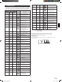
11. ERROR CODES
If you use a wired type remote controller, error codes will appear on the remote
controller display. If you use a wireless remote controller, the lamps on the IR receiver
unitwilloutputerrorcodesbywayofblinkingpatterns.Seethelampblinkingpatterns
and error codes in the table below. An error display is displayed only during operation.
Error display
Wired
remote
controller
Error code
Description
OPERATION
lamp
(green)
TIMER
lamp
(orange)
ECONOMY
lamp
(green)
●
(1)
●
(1)
◊
Serialcommunicationerror
●
(1)
●
(2)
◊
Wired remote controller
communication error
●
(1)
●
(5)
◊
Checkrununnished
●
(2)
●
(1)
◊
UnitnumberorRefrigerantcircuit
address setting error
[SimultaneousMulti]
●
(2)
●
(2)
◊
Indoor unit capacity error
●
(2)
●
(3)
◊
Combinationerror
●
(2)
●
(4)
◊
Connectionunitnumber •
error(indoorslaveunit)
[SimultaneousMulti]
Connectionunitnumbererror•
(indoorunitorbranchunit)
[FlexibleMulti]
●
(2)
●
(7)
◊
Masterunit,slaveunitset-up
error[SimultaneousMulti]
●
(3)
●
(2)
◊
IndoorunitPCBmodel
information error
●
(3)
●
(5)
◊
Manualautoswitcherror
●
(4)
●
(1)
◊
Room temp. sensor error
●
(4)
●
(2)
◊
IndoorunitHeatEx.Middletemp.
sensor error
●
(5)
●
(1)
◊
Indoor unit fan motor error
●
(5)
●
(3)
◊
Drain pump error
●
(5)
●
(7)
◊
Damper error
●
(5)
●
(15)
◊
Indoor unit error
●
(6)
●
(2)
◊
OutdoorunitmainPCBmodel
information error or
communication error
●
(6)
●
(3)
◊
Inverter error
●
(6)
●
(4)
◊
Activeltererror,PFCcircuit
error
●
(6)
●
(5)
◊
TripterminalLerror
●
(6)
●
(10)
◊
DisplayPCBmicrocomputers
communication error
●
(7)
●
(1)
◊
Discharge temp. sensor error
●
(7)
●
(2)
◊
Compressortemp.sensorerror
●
(7)
●
(3)
◊
OutdoorunitHeatEx.liquid
temp. sensor error
●
(7)
●
(4)
◊
Outdoortemp.sensorerror
●
(7)
●
(5)
◊
SuctionGastemp.sensorerror
●
(7)
●
(6)
◊
2-way valve temp. sensor error•
3-way valve temp. sensor error•
●
(7)
●
(7)
◊
Heatsinktemp.sensorerror
●
(8)
●
(2)
◊
Sub-coolHeatEx.gasinlet•
temp. sensor error
Sub-coolHeatEx.gasoutlet•
temp. sensor error
●
(8)
●
(3)
◊
Liquidpipetemp.sensorerror
●
(8)
●
(4)
◊
Currentsensorerror
●
(8)
●
(6)
◊
Discharge pressure sensor •
error
Suctionpressuresensorerror•
Highpressureswitcherror•
●
(9)
●
(4)
◊
Trip detection
●
(9)
●
(5)
◊
Compressorrotorposition
detectionerror(permanentstop)
●
(9)
●
(7)
◊
Outdoorunitfanmotorerror
●
(9)
●
(9)
◊
4-wayvalveerror
●
(10)
●
(1)
◊
Discharge temp. error
●
(10)
●
(3)
◊
Compressortemp.error
●
(10)
●
(4)
◊
Highpressureerror
●
(10)
●
(5)
◊
Lowpressureerror
●
(13)
●
(2)
◊
Branch boxes error
[FlexibleMulti]
Display mode
●
:0.5sON/0.5sOFF
◊
:0.1sON/0.1sOFF
():Numberofashing
[Troubleshooting at the remote controller LCD]
This is possible only on the wired remote controller.
[Self-diagnosis]
Ifanerroroccurs,thefollowingdisplaywillbeshown.(“Er”willappearinthesetroom
temperaturedisplay.)
Error code
EX.Self-diagnosis
9374815173-04_IM.indb 18 9/21/2011 1:45:32 PM
-
 1
1
-
 2
2
-
 3
3
-
 4
4
-
 5
5
-
 6
6
-
 7
7
-
 8
8
-
 9
9
-
 10
10
-
 11
11
-
 12
12
-
 13
13
-
 14
14
-
 15
15
-
 16
16
-
 17
17
-
 18
18
-
 19
19


Fujitsu HRG18LLTA Installation guide
- Category
- Split-system air conditioners
- Type
- Installation guide
Ask a question and I''ll find the answer in the document
Finding information in a document is now easier with AI
Related papers
-
Fujitsu HRG45LHTA Installation guide
-
Fujitsu ARTG18LLTA Installation guide
-
Fujitsu ARGC90GBTH Installation guide
-
Fujitsu ADUH12LUAS1 Installation guide
-
-
Fujitsu AUHA45LULU Installation guide
-
-
-
-
Fujitsu AUU7RLF Installation guide
Other documents
-
 Atlas Metal Industries FL6.3-A Datasheet
-
 GLOBALFLEX Global004 Operating instructions
-
 GLOBALFLEX Global005 Operating instructions
-
MD Building Products 50148 Installation guide
-
GREE Ducted GFH Installation guide
-
Haier AD07SL2VHB Installation guide
-
Haier AW12LC2VHA Installation guide
-
 Rugged Ridge Euro-Style Turn Signal & Side Marker Guards Installation guide
-
Haier AD122XLERA User manual
-
Toshiba RAV-SP420CT-UL User manual


