Page is loading ...

FAIRCHILD MODEL 20
PNEUMATIC HIGH CAPACITY VOLUME BOOSTER
Installation, Operation and Maintenance Instructions
Figure 2. Mounting Bracket 09921. (Sold Separately)
The Model 20 can be mounted in any position without
affecting its operation. It can be mounted to a flat surface
using Mounting Bracket 09921 For more information, see
Figure 1. “Model 20 Outline Dimensions” above.
Clean all pipelines to remove dirt and scale before installa-
tion.
Figure 1. Model 20 Outline Dimensions.
Apply a minimum amount of pipe compound to the male
threads of the fitting only. Do Not use teflon tape as a
sealant. Start with the third thread back and work away
from the end of the fitting to avoid the possibility of contami-
nating the booster. Install the booster in the air line.
The inlet and outlet ports are labeled on the underside of the
INSTALLATION

2
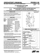
Figure 3. Exploded Drawing for 1:1, 1:2, 1:3, 2:1, & 3:1 Ratios.
booster with the arrows pointing in the direction of the flow.
Tighten connections securely. Avoid undersized fittings
that will limit the flow through the booster and cause a
pressure drop down stream. For more information, see
Figure 1. “Outline Drawing” on page 1.
Oil free air must be applied to the booster.
Use a filter to remove dirt and entrained
liquid in the air line ahead of the booster. If
an air line lubicator is used, it MUST be
located downstream of the booster, to avoid
interference with booster performance.
Valve
Screw
Bonnet
Diaphragm Assembly
Spacer Ring
Spacer Ring
Washer
Spring
Screw
Seal Plate Assembly
Seal Plate Gasket
Body Assembly
Seat Assembly (Nitrile)
Seat Assembly (Silicone)
Seat Assembly (Viton)
Screen
Inner Valve Asm. (Nitrile)
Inner Valve Asm. (Silicone)
Inner Valve Asm. (Viton)
Retainer Plate
Retainer Cap
Screw
1
2
3
4
5
6
7
8
8
9
10
11
7
12
13
9
13
3, 6
13
10
14
15
9
15
3, 6
15
10
16
17
18
Qty. Description
Table 1. Model 20 Components
Item
1
For 19513-11I
2
For 19513-11
NI
3
For 19513-11
AI
4
For 19513-11
JI
5
For 19513-11JNI
6
For 19513-11A
7
For All
19513
8
For 19513
9
For 19513
10
For 19513
-11, -12, -13, -21, -31, -11A, -11J, -12J,
-13J, -21J, -31J, -11JN, -12JN, -13JN,
-21JN, -31JN, -11N, -12N, -13N, -21N,
-31N Service Kits.
-11, -12, -13, -21, -31, -11I, -11N, -12N,
-13N, -21N, -31N, -11NI Service Kits.
-11J, -12J, -13J, -21J, -31J, -11JI,
-11JN, -12JN, -13JN, -21JN, -31JN,
-11JNI Service Kits.
Service Kit Only. (1:1 Ratio)
Service Kit Only. (1:1 Ratio)
Service Kit Only. (1:1 Ratio)
Service Kit Only. (1:1 Ratio)
Service Kit Only. (1:1 Ratio)
Service Kit Only. (1:1 Ratio)
Service Kits.
1
6
1
See Table 3
1
1
1
1
4
1
1
1
1
1
1
1
1
1
1
1
1
2
OPERATION
INSTALLATION (continued)
The Model 20 reproduces a pneumatic signal in a 1:1
ratio or in multiplying or dividing ratios.
(Po = Ps
x R); where Po is output pressure, Ps is
signal pressure, R is ratio.
The information set forth in the foregoing Installation,
Operation and Maintenance Instructions shall not be
modified or amended in any respect without prior
written consent of Fairchild Industrial Products Com-
pany. In addition, the information set forth herein
shall be furnished with each product sold incorporat-
ing Fairchild's unit as a component thereof.
LEGAL NOTICE:
NOTES:

3
1
2
3
1
3
2
3
3
3
4
3
5
3
6
3
7
3
8
3
9
3
10
4
5
11
6
7
8
11
9
10
12
10
13
11
11
12
12
12
13
13
14
15
6
1
1
1
1
1
1
1
1
1
1
1
1
1
4
1
1
1
1
1
1
1
1
1
1
2
Screw
Bonnet
Diaphragm Assembly (Nitrile)
Diaphragm Assembly (Nitrile)
Diaphragm Assembly (Nitrile)
Diaphragm Assembly (Nitrile)
Diaphragm Assembly (Nitrile)
Diaphragm Assembly (Viton)
Diaphragm Assembly (Viton)
Diaphragm Assembly (Viton)
Diaphragm Assembly (Viton)
Diaphragm Assembly (Viton)
Spacer Ring
Gasket
Screw
Seal Plate Assembly
Seal Plate Gasket
Body Assembly
Seat Assembly (Nitrile)
Seat Assembly (Viton)
Screen
Inner Valve Assembly (Nitrile)
Inner Valve Assembly (Viton)
Retainer Plate
Retainer Cap
Screw
Figure 4. Exploded Drawing for 1:4, 1:5, 1:6, 4:1, & 5:1 Ratios.
1.
2.
3.
Before dissassembly, shut off the valve that is supply-
ing air to the booster. This is to prevent air from
escaping. It is not necessary to remove the booster
from the air line.
Remove the two Screws (20) from Figure 3 or (15)
from Figure 4.
Pull out the Inner Valve Assembly (17) from Figure 3
or (12) from Figure 4. Wash the Seat on the Inner
Valve Assembly carefully.
MAINTENANCE
4.
5.
Wipe off any particles that may be attached to rubber
Seat
Assembly (15) from Figure 3 or (10) from Figure 4.
Replace the assembly carefully. For more information,
see Figure 3 on page 2 or Figure 4 on page 3.
Avoid such solvents as acetone, carbon tet-
rachloride and trichlorethylene.
If the standard maintenance procedure does
not correct the trouble, install service kit.
NOTES:
To clean the Model 20, use the following procedure:
Qty. Description
Item
1
For 19513-14
2
For 19513-15
3
For 19513-16
4
For 19513-41
5
For 19513-51
6
For 19513-14J
7
For 19513-15J
8
For 19513-16J
9
For 19513-41J
10
For 19513-51J
11
For All 19513
12
For 19513-14, -15, -16, -41, & -51 Service Kits.
13
For 19513-14J, -15J, -16J, -41J, & -51J
Service Kits.
Table 2. Model 20 Components
Service Kit Only. (1:4 Ratio)
Service Kit Only. (1:5 Ratio)
Service Kit Only. (1:6 Ratio)
Service Kit Only. (4:1 Ratio)
Service Kit Only. (5:1 Ratio)
Service Kit Only. (1:4 Ratio)
Service Kit Only. (1:5 Ratio)
Service Kit Only. (1:6 Ratio)
Service Kit Only. (4:1 Ratio)
Service Kit Only. (5:1 Ratio)
Service Kits.

1
For
19513- 11
2
For
19513- 12
3
For 1
9513-13
4
For
19513-21
5
For
19513-31
6
For 19513-11A
7
For 19513-11
AI
8
For 19513-11I
9
For 19513-11J
10
For 19513-12J
11
For 19513-21J
12
For 19513-11
JI
13
For 19513-11JN
14
For 19513-12JN
15
For 19513-13JN
16
For 19513-21JN
17
For 19513-31JN
18
For 19513-11JNI
19
For 19513-11N
20
For 19513-12N
21
For 19513-13N
22
For 19513-21N
23
For 19513-31N
24
For 19513-11
NI
6
1
6
2
6
3
6
4
6
5
6
6
6
7
6
8
6
9
6
10
6
11
6
12
6
13
6
14
6
15
6
16
6
17
6
18
6
19
6
20
6
21
6
22
6
23
6
24
IS-20000020
Litho in USA
Rev. P 08/06
Leakage
High Bleed
Check Body Screw tightness.
Check Diaphragm.
Check Relief Pintle and Relief Seat
for damage or contamination.
TROUBLE-SHOOTING
Solution (check)
Qty. Description
Item
Table 3. Diaphragm Assembly
MODEL 20 COMPONENTS (continued)
1
1
1
1
1
1
1
1
1
1
1
1
1
1
1
1
1
1
1
1
1
1
1
1
Service Kit Only. (1:1 Ratio)
Service Kit Only. (1:2 Ratio)
Service Kit Only. (1:3 Ratio)
Service Kit Only. (2:1 Ratio)
Service Kit Only. (3:1 Ratio)
Service Kit Only. (1:1 Ratio)
Service Kit Only. (1:1 Ratio)
Service Kit Only. (1:1 Ratio)
Service Kit Only. (1:1 Ratio)
Service Kit Only. (1:2 Ratio)
Service Kit Only. (2:1 Ratio)
Service Kit Only. (1:1 Ratio)
Service Kit Only. (1:1 Ratio)
Service Kit Only. (1:2 Ratio)
Service Kit Only. (1:3 Ratio)
Service Kit Only. (2:1 Ratio)
Service Kit Only. (3:1 Ratio)
Service Kit Only. (1:1 Ratio)
Service Kit Only. (1:1 Ratio)
Service Kit Only. (1:2 Ratio)
Service Kit Only. (1:3 Ratio)
Service Kit Only. (2:1 Ratio)
Service Kit Only. (3:1 Ratio)
Service Kit Only. (1:1 Ratio)
Table 4. Trouble-Shooting
Probelm
Diaphragm Assembly (Nitrile)
Diaphragm Assembly (Nitrile)
Diaphragm Assembly (Nitrile)
Diaphragm Assembly (Nitrile)
Diaphragm Assembly (Nitrile)
Diaphragm Assembly (Silicone)
Diaphragm Assembly (Silicone)
Diaphragm Assembly (Nitrile)
Diaphragm Assembly (Viton)
Diaphragm Assembly (Viton)
Diaphragm Assembly (Viton)
Diaphragm Assembly (Viton)
Diaphragm Assembly (Viton)
Diaphragm Assembly (Viton)
Diaphragm Assembly (Viton)
Diaphragm Assembly (Viton)
Diaphragm Assembly (Viton)
Diaphragm Assembly (Viton)
Diaphragm Assembly (Nitrile)
Diaphragm Assembly (Nitrile)
Diaphragm Assembly (Nitrile)
Diaphragm Assembly (Nitrile)
Diaphragm Assembly (Nitrile)
Diaphragm Assembly (Nitrile)
The information set forth in the foregoing Installa-
tion, Operation and Maintenance Instructions shall
not be modified or amended in any respect without
prior written consent of Fairchild Industrial Prod-
ucts Company. In addition, the information set
forth herein shall be furnished with each product
sold incorporating Fairchild's unit as a component
thereof.
LEGAL NOTICE:
/