Page is loading ...

®
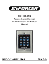
SK-2612-SPQ
Outdoor Stand-Alone/Wiegand
Keypad with Proximity Reader
Manual
Features:
1,000 Users (up to 998 users and 2 duress users)
User code length 4~6 digits
9~18 VDC Operation
Low current draw – 105mA max.
Form C relay output – 2A@12VDC
Adjustable output time – 0.5~99s, or toggle
Built-in tamper alarm and external alarm output
Backlit keypad and multicolor status LED
EM 125kHz
Outdoor rated – IP66
Easy transfer of users to additional devices
EEPROM Memory protects programmed
information in case of power loss
All features programmed directly on the keypad:
No need for an external programmer
Egress input lets users exit the premises
without keying in a code
Can serve as Wiegand reader or controller,
output and input – 26~37 bits
2-Door interlock
Extreme cold tolerance to -40° F (-40° C)
Sturdy black ABS plastic housing

ENFORCER Outdoor Stand-Alone/Wiegand Keypad with Proximity Reader
2 SECO-LARM U.S.A., Inc.
This page is for installers looking to do a basic installation and programming of the keypad. For more
in-depth installation and programming instructions, see "Table of Contents" on pg. 4.
Quick Wiring Diagram:
Mounting Diagram:
NOTE: For DC-powered electric strikes, connect the included diode as close as possible and in parallel
with the electric strike. This absorbs possible electromagnetic interference to prevent operation
of the strike from damaging the keypad. Do not connect a diode when using electromagnetic
locks or with AC powered strikes.
Quick Installation Guide:
Orange
–
Output (N.C.)
Blue
–
Output (N.O.)
Yellow
–
Egress Input (N.O.)
Black
–
Ground (
–
)
Gray
–
Tamper Alarm Output (GND)
Purple
–
Output (COM)
Red
–
12VDC (+)
12VDC
Power
Supply
(+)
Egress
Button
(
–
)
(+)
(
–
)
Or
Cathode
Electric
Lock
IN4007
Output Relay
N.O. Output for Fail-secure Lock
N.C. Output for Fail-safe Lock
(+)
Alarm
(
–
)
Diode IN4007
(See note below)
Door Sensor
Brown
–
Door Sensor Input*
Green
–
Data 0
White
–
Data 1
Wiegand
Controller
2
3 4
9 0
7 8
5 6
*Connect to ground if unused
Housing base
Security screw
Drill at least ø
3
/
8
"
(ø9mm) wiring hole
Choice of 2 pairs of
mounting holes

ENFORCER Outdoor Stand-Alone/Wiegand Keypad with Proximity Reader
SECO-LARM U.S.A., Inc. 3
Quick Programming Guide:
Programming Tips:
Master programming code (6 digits) should be programmed before any other programming.
A steady red LED indicates that keypad is powered on and ready. The LED will change to orange
and a single beep will sound to indicate the device has entered programming mode.
Programming Instructions:
Follow the instructions below if the following covers your needs:
A new master programming code.
Setting one user code.
Setting one user card
A door-unlocked time of 4 seconds after the output is activated.
Access mode / security level set to "card or code" (default)
NOTE: It's important to choose and fully understand the security level before adding users. For other
security levels besides the default, read their setup instructions carefully before proceeding.
1. Enter base programming mode:
NOTE: is the factory default master programming code. A new master
programming code (6 digits) should be set the first time you enter programming mode.
2. Set the master programming code (6 digits):
NOTE: is the new master programming code and must be entered twice.
3. Set a user card to operate the output (unlock the door):
Read Card
NOTES:
chooses user ID #15 of 998 possible user IDs (0~997).
To add other users (card or code) do not repeat the initial function code .
4. Set a user code to operate the output (unlock the door):
NOTES:
chooses user ID #10 of 998 possible user IDs (0~997).
is the new user code for user ID #10 (4~6 digits).
Do not assign the user code 8888 to any user ID.
To add other users (card or code) do not repeat the initial function code .
5. Set the output time (skip this step if the default value of 5 seconds is acceptable):
NOTE: sets the output delay time for 4 seconds.
6. Exit programming mode:
One short beep will sound to indicated that the keypad has exited programming mode.

ENFORCER Outdoor Stand-Alone/Wiegand Keypad with Proximity Reader
4 SECO-LARM U.S.A., Inc.
Operating voltage
9~18
VDC
Current draw
Standby
40
mA@12VDC
Active
105
mA@12VDC (max.)
Outputs
Form C
2
A@12VDC
Alarm
2.5A@12VDC
Wiegand
26~37 bits, PIN output bits
–
4, 8, or 10
Egress input
N.O. Ground
Door sensor input
N.C. Ground
Wiegand input
26~37 bits, PIN input bits
–
4, 8, or 10
Card type
EM 125kHz
Enclosure material
Black ABS plastic
Operating temperature
-
40°~140° F (
-
4
0°~60° C)
Operating humidity
1
0~90%
non
-
condensing
Dimensions
1
15
/
16
"x4
3
/
4
"x
15
/
16
" (49x120x24
mm)
Weight
5.8
-
oz (
165
g)
Specifications:
Table of Contents:
Overview: Parts List:
15
/
16
"
(24mm)
4
3
/
4
"
(
120m
m)
33
7
/
16
"
(850mm)
1
15
/
16
"
(
49m
m)
1x Keypad
1x Security wrench
1x Diode
2x Mounting screws
2x Plastic screw anchors
1x Master add card*
1x Master delete card*
1x Manual
*User proximity cards or key fobs
sold separately (see pg. 20)
2
3 4
9 0
7 8
5 6
Quick Installation Guide:
................................
..............
2
Mounting Diagram: ....................................................... 2
Quick Wiring Diagram: ................................................. 2
Quick Programming Guide: .......................................... 3
Table of Contents: ........................................................ 4
Specifications: .............................................................. 4
Overview: ...................................................................... 4
Parts List: ...................................................................... 4
LED Indicators and Device Sounds: ............................ 5
Important Notes: ........................................................... 5
Installation: ................................................................... 5
Wiring Chart:................................................................. 6
Getting Ready to Program:........................................ 6-7
Programming Format and Default Values: ................... 7
Programming the Master Programming Code: ............ 8
Setting the Keypad Operation Mode: ........................... 8
Programming the Access Mode / Security Level: .... 8~9
Programming User Proximity Cards: ...................... 9~11
Programming User Codes:
................................
...
11~12
Changing the User Code for an Existing User: .......... 12
Programming Duress Codes or Cards: ...................... 13
Deleting Users: ..................................................... 13~14
Programming Output Mode and Time: ................. 14~15
Programming Notification Sounds, LED, Backlight: ... 15
Programming the External Alarm Output: ............ 15~16
Programming the Wrong-Code Lockout/Alarm: ......... 16
Setting up a Two-Door Interlock System:................... 17
Duplicating Users to Other Keypads: ......................... 18
Wiegand Controller Mode:.................................... 18~19
Wiegand Reader Mode: ............................................. 19
Troubleshooting: ......................................................... 19
Resetting to Factory Default and Programming
Add/Delete Cards: ................................................ 20
Accessories Available from SECO-LARM:................. 20
Important Notes/Warnings.......................................... 20
Warranty: .................................................................... 20

ENFORCER Outdoor Stand-Alone/Wiegand Keypad with Proximity Reader
SECO-LARM U.S.A., Inc. 5
Status Sounds LED
Power on in standby mode -- Red steady
In base programming mode 1 Beep Red flashing
In function programming mode 1 Beep Orange steady
Exit programming mode 1 Beep Red steady
Successful operation 1 Beep Green flash once
Unsuccessful operation 3 Beeps
Built-in alarm Rapid beeping* Red flashing rapidly
LED Indicators and Device Sounds:
*De-activate the built-in alarm by entering a valid user code.
1. Find a suitable location to mount the keypad. Install at a
height convenient to most users.
2. Using the included security wrench, remove the security
screw located on the bottom of the keypad (Fig. 1).
3. Carefully remove the keypad from the housing base,
sliding the keypad slightly upwards.
4. Using the housing base as a template, mark the holes
needed for the wiring and mounting screws and drill
needed holes (choose either of the two pairs of mounting
holes). Ensure that the wiring hole is large enough to
allow the wiring to be pushed in without crimping.
5. Run wiring through the wall to the wiring hole in the wall
6. Thread the keypad wires through the center of the keypad
base and connect all according to "Wiring Chart" on pg. 6.
7. Carefully push the wires through the hole in the wall.
8. Install the base using the included mounting screws and mounting screw anchors (if necessary).
Ensure the correct orientation as shown in Fig. 1.
9. Finish assembly by reattaching the keypad to the base and securing with the security screw.
Important Notes:
1. Always disconnect power before servicing the keypad. Do not apply
power until all connection wiring
is completed.
2. The keypad must be properly grounded. Use a minimum 22AWG wire connected to the common
ground wire. Failure to do so may damage the unit.
3. All wiring and programming should be done by a professional installer to reduce the risk of improper
installation.
4. Be sure to store this manual in a safe place for future reference.
Installation:
Fig. 1
Drill
2 mounting
holes
Drill at least ø
3
/
8
"
(ø9mm) wiring hole
NOTE: For weatherproof installation, add a
bead of silicone sealant around the
base where it meets the wall.
Security
screw
IF USING THE KEYPAD WITH A MECHANICALLY OPERATED DOOR OR
GATE, MOUNT THE UNIT AT LEAST 15' (5m) FROM THE DOOR OR GATE
TO PREVENT USERS FROM BEING CRUSHED OR PINNED. FAILURE TO
DO SO MAY RESULT IN SERIOUS INJURY OR DEATH.

ENFORCER Outdoor Stand-Alone/Wiegand Keypad with Proximity Reader
6 SECO-LARM U.S.A., Inc.
Wiring Chart:
Color
Function
Description
Red
Power (+)
Connect to +12VDC power supply
Black
Ground (
-
)
Connect to Ground
Yellow
Egress Input
N.O. Pushbutton contact to ground. Press button to activate the output
Brown
Door Sensor
Connect to a magnetic contact or door sensor
Blue
Output N.O.
NO/NC/COM, relay output, max. 3A@12VDC
Purple
Output COM
Orange
Output N.C.
Gray
Alarm Output
Transistor ground output, max. 2.5A@12VDC.
Green
Data 0
Wiegand controller
White
Data 1
Wiegand controller
See also Quick Wiring Diagram on pg. 2 for a sample application and for the use of the included diode.
The keypad is activated by keypad user codes (4~6 digits) and/or user proximity cards.* All user
codes/cards must have a unique User ID (between 0 and 997 for users and 998 or 999 for duress). It is
important to record all User IDs for future management tasks.
Card types:
There are four types of cards:
Master add card
†
– Used only to quickly add user cards without entering programming mode. This
will assign each user card to the first available user ID in consecutive order.
Master delete card – Used only to quickly delete user cards without entering programming mode.
User cards – Up to 998 user cards (user IDs 0~997) can be assigned to activate the relay.
Duress cards – Up to 2 duress cards (user ID s 998~999) can be assigned. Duress cards are used
under duress to activate the relay while triggering an alarm.
Keypad code types:
There are three types of keypad user codes:
Master programming code (6 digits) – Used only to enter programming mode and cancel alarms.
There can be only one master programming code per keypad.
User codes (4~6 digits) – Up to 998 user codes (user IDs 0~997) can be assigned. User codes are
used to activate the relay and cancel alarms.
Duress codes (4~6 digits) – up to 2 duress codes (user ID s 998~999) can be assigned. Duress
codes are used under duress to activate the relay while triggering an alarm.
Security Levels:
There are four possible security levels (see "Programming the Access Mode / Security Level," pgs. 8~9
for more detail):
Card only
Card or code (default)
Card+code
Multiple cards/user codes
Getting Ready to Program:
*In this manual "card" refers to either proximity cards or fobs.
†
If the master add/delete cards are lost, see "Resetting to Factory Default and Programing Add/Delete Cards," pg. 20)

ENFORCER Outdoor Stand-Alone/Wiegand Keypad with Proximity Reader
SECO-LARM U.S.A., Inc. 7
In this manual, the format used for programming the keypad is as follows:
A single-digit ( ) FUNCTION CODE to tell the keypad what is being programmed.
A varying number of digits ( ) to represent the parameters of that FUNCTION.
The key to confirm programming of the FUNCTION and exit to base programming mode.
The key to exit programming mode and return to standby mode.
The following is a list of the different programming functions:
Function
Code*
Parameters Default Functions and Values Pg. #
0
Master programing code
Default 123456, code length 6 digits
8
1
Add user/duress cards/codes
No default, must be
programmed
9~13
2
Delete user/duress cards/codes
No default, must be programmed
13~14
3
Output mode/time
Momentary 5 seconds
14~15
4
Access mode / security level
Card or code
8~9
5
Set external alarm/time
1 minute
15~16
6
Wrong
-
code
lockout/alarm
Lockout disabled
16
7
Sounds, LED, backlight
Operation mode
All ON
Stand-alone mode
15
8
8
Set Wiegand output/input formats
Output/input bits
–
26, PIN output/input bits
–
4
19
9
Set interlock mode,
Duplicate to another device
Interlock default
–
OFF
Duplicate – no default, must be programmed
17
18
*Press the function code only to enter the programming mode for that function. It should not be repeated
between each parameter.
Programming Format and Default Values:
Getting Ready to Program (Continued):
Enter and Exit Base Programming Mode:
All programming of the keypad is done from base programming mode.
1. Enter base programming mode using the master programming code:
– (One beep will sound and the LED will flash red)
NOTE: is the master programming code (6 digits). is the default
(see "Programming the Master Programming Code," pg. 8).
2. Within the base programming mode, press a function code (see Programming Format and Default
Values," below) to enter function programming mode (the LED changes to steady orange). The
function code is not repeated between programming different items under the same function code.
3. Exit function programming mode: Press the key.
4. Exit base programming mode: Press the key or wait 25 seconds to exit automatically.
NOTES:
DO NOT DISCONNECT THE KEYPAD FROM POWER WHILE IN PROGRAMMING MODE.
Disconnecting the unit while in programming mode may cause a memory error.
The LED will flash green once indicating the unit has entered base programming mode and with a
successful programming step. If you are unsure which function programming mode you are in,
press the key to return to base programming mode and press the function code to proceed.
Except for changing the user code for an existing User ID or using the Master add and Master
delete cards, for all programming functions the keypad must first be in base programming mode.

ENFORCER Outdoor Stand-Alone/Wiegand Keypad with Proximity Reader
8 SECO-LARM U.S.A., Inc.
Programming the Master Programming Code:
Programming the Access Mode / Security Level:
Setting the Keypad Operation Mode:
The keypad can operate as a standalone keypad, a controller connected to an external Wiegand
reader, or a Wiegand reader. To set the operating mode
, use the following general formula from within
base programming mode (see "Enter and Exit Base Programming Mode," pg. 7):
– Operating Mode function code (a short beep will sound and the LED will change to orange)
– Set the operating mode
Operating Mode:
– Standalone or controller mode (default)
– Wiegand reader mode
NOTE: The key returns you to base programming mode (the LED will flash red). Exit programming
mode by pressing the key (see "Enter and Exit Base Programming Mode," pg. 7).
It is important to program the access mode / security level before adding users as this will affect user
setup. In all modes except the "card+code" security level, a user ID may be assigned a card* or a
user code, but not both. To give the same person both a card and a code requires two user IDs. Due to
the exceptional operation of the "card+code" security level, see the notes for this security level below.
The keypad can be programmed to one of four access modes / security levels:
Card only – a user must use a card for access
Either card or code – a user may use either a card or a user code for access (default)
Card+code – a user must use both a card and user code for access
NOTES:
In this security level, the card should be assigned fir
st. The keypad will automatically assign each
entered card a temporary user code 8888. This code will not activate the lock and must be
changed before use.
If you change to this security level after adding users, all existing card users will be given the
temporary user code 8888 which then must be changed for each user.
If you change to this security level after adding users, all existing code users have to be
reprogrammed by adding a card, which will assign them the temporary user code 8888.
The 8888 code for each card must be changed using the steps listed under "Changing the User
Code for an Existing User," pg. 12, and not using the regular steps for adding a user code.
The master programming code is used to enter base programming mode and to cancel alarms. The
master programming code does not serve as a user code to activate the keypad output.
1. Enter base programming mode (see "Enter and Exit Base Programming Mode," pg. 7).
2. Enter the new master programming code (6 digits):
(where "X" is the new master programming
code)
3. Exit programming mode: Press the key or wait 25 seconds to exit automatically.

ENFORCER Outdoor Stand-Alone/Wiegand Keypad with Proximity Reader
SECO-LARM U.S.A., Inc. 9
Programming User Proximity Cards:
Programming the Access Mode / Security Level (Continued):
You should program user cards before programming user codes, especially if you are using the
"card+code" security level.
IMPORTANT NOTES:
The system assigns a temporary user code 8888 to each card under the "card+code" security level.
If at a later time, you change the security level to "card+code" each previously entered card will have
this 8888 user code as well.
In "card+code" security level, you must remember to change that code before first use. The 8888
user code does not allow access (see "Changing the User Code for an Existing User, pg. 12).
There are multiple ways to program proximity cards. Proximity cards may be assigned to User IDs
between 0 and 997. When programming cards, use the following general formula after entering base
programming mode (see "Enter and Exit Base Programming Mode," pg. 7):
Multiple user codes or cards – multiple (2~9) user codes or cards are required for access. Any
combination of user codes or cards in any order up to the set number must be used with no more
than 5 seconds between each code or card. No particular user code or card can be repeated. This is
used for extremely secure areas requiring authentication by more than one person.
NOTES:
In multiple user code/card mode, if the same card user code is repeated or a wrong card/code is
used, the device will return to standby without triggering the output.
In multiple user code/card mode, the elapsed time between each user code/card must not
exceed 5 seconds, otherwise, the device will return to standby.
When programming the access mode / security level, use the following general formula from within base
programming mode (see "Enter and Exit Base Programming Mode," pg. 7):
( )
– Program Access Mode function code (LED will change to steady orange)
– Access Mode
Access Mode / Security Level:
– User card access only
– User card+code
– Either user card or code (default)
~ – Multiple user cards or codes (the second number 2~9 sets the number of
cards/codes required for access).
NOTE: The key returns you to base programming mode (the LED will flash red). Exit programming
mode by pressing the key (see "Enter and Exit Base Programming Mode," pg. 7).
Examples:
1. Set the access mode to card only:
2. Set the access to require four user codes/cards:

ENFORCER Outdoor Stand-Alone/Wiegand Keypad with Proximity Reader
10 SECO-LARM U.S.A., Inc.
Programming User Proximity Cards (Continued):
Individually by Reading Cards:
Read Card – After a short beep, you may continue to add cards by repeating
these steps, but without repeating the function code .
– Add Users function code (a short beep will sound and the LED will change to steady orange)
– to – 998 unique User IDs to trigger the device (if
is omitted, the device will
assign the user card to the first available User ID.)
Individually by Card Numbers (If Using Cards with Printed Numbers):
– After a short beep, you may continue to add cards by repeating
these steps, but without repeating the function code .
– Add Users function code (a short beep will sound and the LED will change to steady orange)
– 8~10 card number (the device will assign the user code to the first available User ID)
Adding Cards in a Large Batch (If Using Cards with Printed Numbers):
This method allows the addition of up to 998 cards in a single batch. This is especially useful in the
initial setup. This process adds the cards in consecutive order, assigned to available user IDs
consecutively.
– The process will take up to 2 minutes
– Add Users function code (a short beep will sound and the LED will change to steady orange)
– to – the beginning user ID
–the number of cards/fobs to be added
– the card number (8~10 digits) for the first card (or read the first card in the sequence)
NOTES:
Note that in the step above, you may add the first card number, or you can read the first card.
The user IDs will be assigned in consecutive order beginning from the beginning user ID.
The card numbers must be in consecutive order with no gaps in the numbering sequence and
must start with the lowest number.
With the Master Add Card:
The Master Add Card allows you to enter cards quickly without entering programming mode. It takes
you directly into the "add user" function mode without needing to enter the master programming code
and the add user function code. Once in this mode, you made add cards using any of the methods
described above, but omitting the . When complete, present the Master Add Card again to return to
standby mode.
NOTES:
It is important to record each user ID assigned in order to simplify future user management.
A user ID can only have a single card or single code assigned (except by using the method
described in "Changing the User Code for an Existing User," on pg. 12 when in the "card+code"
security level). If you try to add a card to an existing user ID that already has a user code assigned,
the user code will be removed.

ENFORCER Outdoor Stand-Alone/Wiegand Keypad with Proximity Reader
SECO-LARM U.S.A., Inc. 11
User codes may be assigned to User IDs between 0 and 997. Do not
use this method for adding a user
code to an existing card user.
Programming User Codes Individually:
When programming user codes, use the following general formula after entering base programming
mode (see "Enter and Exit Base Programming Mode," pg. 7):
– After a short beep, you may continue to add users by repeating
these steps, but without repeating the function code .
– Add Users function code (a short beep will sound and the LED will change to steady orange)
– to – 997 unique User IDs to trigger the device (if
is omitted, the device will
assign the user code to the first available User ID)
– User code – 4~6 digits (do not use the user code 8888)
With the Master Add Card:
The Master Add Card allows you to enter codes quickly without entering programming mode. It takes
you directly into the "add user" function mode without needing to enter the master programming code
and the add user function code. Once in this mode, you made add codes using the methods
described above, but omitting the . When complete, present the Master Add Card again to return to
standby mode.
NOTES:
It is important to record each User ID assigned in order to simplify future user management.
A user ID can only have a single card or single code assigned (except by using the method
described in "Changing the User Code for an Existing User," on pg. 12 when in the "card+code"
security level). If you try to add a user code to an existing user ID that already has a user card
assigned, the user card will be removed.
Programming User Codes:
Programming User Proximity Cards (Continued):
Additional users may be entered in succession without repeating the function code .
The
key returns you to base programming mode (the LED will flash red). Exit programming mode
by pressing the key (see "Enter and Exit Base Programming Mode," pg. 7).
Examples:
1. Program user card for User ID #0:
Read Card
2. Program a user card allowing the device to auto-assign to the first available User ID (not
recommended unless you have a complete record of already assigned User IDs):
Read Card
3. Program a batch of 50 cards, starting with card# 23456789 and beginning with user ID #0:
(or read card# 23456789)
NOTE: The add user function code places you into this function programming mode. Press the add
user function code only before adding the first user. To continue to add other users in the same
session, do not repeat the add user function code .

ENFORCER Outdoor Stand-Alone/Wiegand Keypad with Proximity Reader
12 SECO-LARM U.S.A., Inc.
Programming User Codes (Continued):
Changing the User Code for an Existing User
Programming Duress Codes and Cards:
Additional users may be entered in succession without repeating the function code .
The
key returns you to base programming mode (the LED will flash red). Exit programming mode
by pressing the key (see "Enter and Exit Base Programming Mode," pg. 7).
Examples:
1. Program user code for User ID #0:
2. Program a user code allowing the device to auto-assign to the first available User ID
(not recommended unless you have a complete record of already assigned User IDs):
3. Program two user codes – 67890 for User ID #201, and 654321 for User ID #17:
wait for beep, then
NOTE: The add user function code places you into this programming mode. Press the add user
function code only before adding the first user. To continue to add other users in the same
session, do not repeat the add user function code .
For a Code User:
You can change the user code for an existing user without going into programming mode if you know
both the current user code and user ID. Users can also use this method to
change their own user codes
to something they can more easily remember. This procedure is done outside programming mode.
Use the following formula in standby mode to change an existing user code.
– User ID
–Current user code
– New user code (4~6 digits, entered twice, do not use the user code 8888)
In "Code+Card" Security Level:
If you have set the security level to "card+code," you must use this method to change the temporary
8888 user code that the device automatically assigns to card users. Use the following formula in
standby mode to change a user code.
Read Card
–Current user code (temporary default 8888)
– New user code (4~6 digits, entered twice)
Duress codes/cards are assigned to user IDs 998 and 999 to trigger an alarm while unlocking the door.
Duress codes/cards are programmed in the same manner as regular users, except that you must
particularly assign them to user ID 998 or 999. (see "Programming User Proximity Cards," pgs. 9~11
and Programming User Codes," pgs. 11~12):

ENFORCER Outdoor Stand-Alone/Wiegand Keypad with Proximity Reader
SECO-LARM U.S.A., Inc. 13
Deleting Users:
Deleting Individual User/Duress Codes or cards:
To delete a user or duress code/card, use the following general formula from within base programming
mode (see "Enter and Exit Base Programming Mode," pg. 7):
…
– Delete Users function code (a short beep will sound and the LED will change to steady orange)
Either:
– to – the user/duress ID (Duress IDs must use this method)
Or: – – the user code (4-6 digits)
Or: – Read card
Deleting Cards with the Master Delete Card
The Master Delete Card works similar to the Master Add Card, but allows you to delete cards/codes
quickly without entering programming mode. The card takes you directly into the "delete user" function
mode without needing to enter the master programming code and the delete user function code.
Once in this mode, you delete cards/codes using any of the methods described above, but omitting the
. When complete, present the Master Delete Card again to return to standby mode.
Deleting All Users:
To delete all users while retaining the keypad configuration, use the following formula from within base
programming mode (see "Enter and Exit Base Programming Mode," pg. 7):
– Delete Users function code (a short beep will sound and the LED will change to steady orange)
– Master programming code
NOTES:
Duress IDs cannot be deleted using their user code or card, but must be deleted with the Duress ID.
Any of the above methods will delete the user ID along with any code/card connected to it.
The
key returns you to base programming mode (the LED will flash red). Exit programming mode
by pressing the key (see "Enter and Exit Base Programming Mode," pg. 7).
Programming Duress Codes and Cards (Continued):
IMPORTANT NOTES:
A duress user ID can only have a single card or single code assigned (except by using the method
described in "Changing the User Code of an Existing User," on pg. 12 when in the "card+code"
security level). If you try to add a code to an existing duress user ID that already has a card
assigned, the card will be removed and vice versa.
The duress alarm will sound f
or the number of minutes set for the external alarm (see "Programming
the External Alarm Output," pgs. 15~16) and cannot be silenced before that time is up.
If a user card or code is used while the duress alarm is sounding, the alarm will continue to sound
and not stop after the programmed alarm output time expires. When this happens, the duress
code/card must be used again, after which the timing cycle will start again and the alarm will stop
only after that time has expired.
In code+card security level, either the duress card or code will trigger the duress alarm.

ENFORCER Outdoor Stand-Alone/Wiegand Keypad with Proximity Reader
14 SECO-LARM U.S.A., Inc.
Programming the Output Mode and Time:
Examples:
1. Delete User ID #501:
2. Delete user code #6905:
3. Delete a user card #56789012:
4. Delete a user card by presenting the card:
Read Card
5. Delete all users (if the master programming code is 631732):
The relay can be programmed to toggle the relay ON/
OFF (toggle mode), or to trigger for a programmed
length of time up to 99 seconds before automatically turning OFF. The output can be used for locking or
unlocking a door or for a variety of functions that can be controlled with the keypad.
When programming the output mode and time, use the following general formula from within base
programming mode (see "Enter and Exit Base Programming Mode," pg. 7):
– Program Output Mode and Time function code (a short beep will sound and the LED will
change to steady orange)
– Output Mode and Output Time
Output Mode and Output Time:
– Start/stop (toggle) mode. In this case, the output starts when a user code is entered, and
stops when a user code is entered again.
to – The output triggered by a user code lasts up to 99 seconds before automatically
turning off (1=500ms, default: 5 seconds).
NOTES:
For programming the output timing, 1=500ms. 2~99 represents full seconds.
The
key returns you to base programming mode (the LED will flash red). Exit programming mode
by pressing the key (see "Enter and Exit Base Programming Mode," pg. 7).
Examples:
1. Set the output to toggle mode:
2. Set the output to 60 seconds:
Deleting Users (Continued):

ENFORCER Outdoor Stand-Alone/Wiegand Keypad with Proximity Reader
SECO-LARM U.S.A., Inc. 15
Programming Built-In Notification Sounds, LED, and Backlight:
Programming the External Alarm Output:
The keypad notification sounds, LED, and backlight may be disabled. Setting the keypad notification
sounds affects all sounds from the keypad, including keypad presses, successful card/code entry
notifications, duress alarm, and wrong-code alarm. When programming, use the following general
formula from within base programming mode (see "Enter and Exit Base Programming Mode," pg. 7):
– Program Notification Sounds/LED/Backlight function code (LED will change to steady orange)
– Enable/Disable Notification Sounds/LED/Backlight
Enable/Disable Notification Sounds/LED/Backlight:
– Disable notification sounds
– Enable notification sounds (default)
– Disable LED
– Enable LED (default)
– Disable keypad backlight
– Enable keypad backlight (default)
NOTES:
Disabling the notification sounds affects only the internal sounds and not the external alarm output.
The duress alarm and wrong-code alarm will trigger both the internal notification beep and the
external alarm, depending on their settings.
The
key returns you to base programming mode (the LED will flash red). Exit programming mode
by pressing the key (see "Enter and Exit Base Programming Mode," pg. 7).
The external alarm sounds an external alarm when the tamper, duress, or wrong-code alarm (if
enabled, see "Programming the Wrong-Code Lockout/Alarm," pg. 16) is triggered. To program, use the
following formula in base programming mode (see "Enter and Exit Base Programming Mode," pg. 7):
– Program Alarm function code (LED will change to steady orange)
– Alarm Disable/Enable and Alarm Time
Alarm Disable/Enable and Alarm Time:
– Disable alarm (factory default)
to – Enable and set the alarm time, 1~3 minutes (factory default, 1 minute)
NOTE: The key returns you to base programming mode (the LED will flash red). Exit programming
mode by pressing the key (see "Enter and Exit Base Programming Mode," pg. 7).
Examples:
Disable the external alarm:
Enable the external alarm and set it to 2 minutes:

ENFORCER Outdoor Stand-Alone/Wiegand Keypad with Proximity Reader
16 SECO-LARM U.S.A., Inc.
Programming the Wrong-Code Lockout/Alarm:
The device can be programmed to either lockout or sound an internal alarm after 10 successive wrong
cards/codes. The lockout continues and the LED flashes red for 10 minutes and cannot be reset before
then. The built-in notifications and external alarm sounds for the length of time set in the alarm settings
(1~3 minutes, see notes below), or until stopped with a valid master programming code or user code.
When programming the wrong code lockout, use the following general formula from within base
programming mode (see "Enter and Exit Base Programming Mode," pg. 7):
– Program Wrong-Code Lockout/Alarm function code (LED will change to steady orange)
–Disable or Enable/Configure the Wrong-Code Lockout/Alarm
Disable or Enable/Configure Wrong-Code Lockout/Alarm:
– Disable wrong-code lockout (factory default)
– Enable wrong-code lockout to deny access for 10 minutes
– Enable wrong-code alarm to sound the keypad notifications / external alarm
NOTES:
If wrong-code lockout is enabled, the LED will flash red and all access will be denied for 10 minutes
after 10 successive wrong cards/codes.
If wrong-code alarm is enabled, the LED will flash red and the built-in notifications (if enabled, see
"Programming the Notification Sounds, LED, and Backlight," pg. 15) and external alarm (if enabled,
see "Programming the External Alarm Output, pgs. 15~16) will sound and continue for the length of
time programmed for the alarm or until a valid master programming code or user code is entered.
This setting requires either or both the built-in notifications and external alarm output to be enabled
and the alarm timing is set by the external alarm settings.
The key returns you to base programming mode (the L
ED will flash red). Exit programming mode
by pressing the key (see "Enter and Exit Base Programming Mode," pg. 7).
Examples:
1. Disable the wrong-code lockout:
2. Enable the wrong-code lockout to deny access for 10 minutes:
3. Enable the wrong-code alarm for the set time (disabled with a valid master code or user code/card):

ENFORCER Outdoor Stand-Alone/Wiegand Keypad with Proximity Reader
SECO-LARM U.S.A., Inc. 17
Setting up a Two-Door Interlock System with Two Keypads:
In this application, two keypads are each connected to separate door locks and egress pushbuttons.
While one door is open, the other cannot be opened.
Two-Door Interlock Wiring Diagram:
Door 1
electric
Lock
Egress
Button
Door 1 Sensor
(+)
(
–
)
Alarm
Red (+)
Purple (COM)
Gray (GND)
Black (–)
Yellow (N.O.)
Brown
Blue (N.O.)
Orange (N.C.)
or
Door 2 Sensor
Egress
Button
Alarm
Cathode
Output Relay
N.O. Output for
Fail-secure Lock
N.C. Output for
Fail-safe Lock
Red(+)
Purple (COM)
Gray (GND)
Black (–)
Yellow (N.O.)
Brown
Blue (N.O.)
Orange (N.C.)
Cathode
Diode IN4007
(see note
below)
Green – Data 0
Output Relay
N.O. Output for
Fail-secure Lock
N.C. Output for
Fail-safe Lock
White – Data 1
Green – Data 0
White – Data 1
(
–
)
(
–
)
(+)
(+)
(
–
)
(
–
)
(+)
(+)
or
Door 2
Door 1
Wiegand
Controller
Wiegand
Controller
12VDC
Power Supply
Door 2
electric
Lock
2
3 4
9 0
7 8
5 6
2
3 4
9 0
7 8
5 6
NOTE:
For
DC
-
powered electric strikes, connect the included diode as close as possible and in parallel with
the electric strike. This absorbs possible electromagnetic interference to prevent operation of the
strike from damaging the keypad. Do not connect a diode when using electromagnetic locks or with
AC powered strikes.
Programming the Interlock System:
When programming the interlock system, use the following general formula from within base
programming mode (see "Enter and Exit Base Programming Mode," pg. 9):
– Program the Interlock System function code (LED will change to steady orange)
– Disable or Enable the Interlock System
Disable or Enable the Interlock:
– Disable the interlock (factory default)
– Enable the interlock
NOTE: The key returns you to base programming mode (the LED will flash red). Exit programming
mode by pressing the key (see "Enter and Exit Base Programming Mode," pg. 7).

ENFORCER Outdoor Stand-Alone/Wiegand Keypad with Proximity Reader
18 SECO-LARM U.S.A., Inc.
Duplicating Users to Other Keypads:
User data can be duplicated from one keypad to
other keypads (up to 10 at one time) that supports
this function. All user data will be transferred to the
second unit (taking about 3 minutes for 1,000
users), overwriting any existing user data.
Connect the keypads in parallel as shown in Fig. 1,
all wires to the same corresponding color.
Make sure that both keypads have the same
master programming code. To transfer user data,
use the following general formula from within base programming mode on the main keypad containing
the user data (see "Enter and Exit Base Programming Mode," pg. 7):
– Initiate User Data Transfer function code (LED will change to steady orange)
NOTES:
All keypads must support the data transfer function and have the same master programming code.
Any user data existing on the additional devices will be overwritten.
When transfer is complete, a short beep will sound, the LED will flash green once and ch
ange to red.
Exit programming mode by pressing the key after transfer is complete.
Wiegand Controller Mode:
The keypad can work as a controller connected to an external Wiegand reader.
Wiegand Controller Mode Wiring Diagram:
Wiegand
Reader
Orange
–
Output (N.C.)
Blue
–
Output (N.O.)
Yellow
–
Egress Input (N.O.)
Black
–
Ground (
–
)
Gray
–
Tamper Alarm Output (GND)
Purple
–
Output (COM)
Red
–
12VDC (+)
12VDC
Power
Supply
(+)
Egress
Button
(
–
)
(+)
(
–
)
Or
Cathode
Electric
Lock
Output Relay
N.O. Output for Fail-secure Lock
N.C. Output for Fail-safe Lock
(+)
Alarm
(
–
)
Diode IN4007*
Door Sensor
Brown
–
Door Sensor Input
Green
–
Data 0
White
–
Data 1
GND
+12V
D0
D1
2
3 4
9 0
7 8
5 6
NOTE:
For DC
-
powered
electric strikes, connect the included diode as close as possible and in parallel with
the electric strike. This absorbs possible electromagnetic interference to prevent operation of the strike
from damaging the reader/keypad. Do not connect a diode when using electromagnetic locks or with
AC powered strikes.
(+)
(
–
)
12VDC
Power Supply
Red
Black
Green (D0)
White (D1)
Fig.
1
2
3 4
9 0
7 8
5 6
2
3 4
9 0
7 8
5 6
To additional
units

ENFORCER Outdoor Stand-Alone/Wiegand Keypad with Proximity Reader
SECO-LARM U.S.A., Inc. 19
Unit fails to accept a new user/duress
code/card
Ensure the User ID assigned is between 0 and 997 for users and
either 998 or 999 for duress codes/cards
Ensure the user code is between 4~6 digits long and not already
assigned to another user
Unit fails to respond to a programmed
user code/card
Ensure the unit is in standby mode by pressing the
key until the
LED becomes steady red
Troubleshooting:
The keypad can work as a standard Wiegand reader,
connected to an external controller. Be sure to set the
keypad operation mode to Wiegand reader mode (see
"Setting the Keypad Operation Mode," pg. 8).
Connect the keypad to the controller as shown in the
wiring diagram on the right.
NOTES:
The reader will override most controller settings.
Wiegand Reader Mode:
Set Wiegand Input Bits/PIN Input Format:
Set the Wiegand input bits and format according to the output format of the external reader. To set the
Wiegand input bits and the Wiegand PIN output format, use the following general formula from within
base programming mode (see "Enter and Exit Base Programming Mode," pg. 7):
– Set Wiegand Input Bits/PIN Input Format function code (a short beep will sound and the LED
will change to steady orange)
– Wiegand Input Bits/PIN Input Format
Wiegand Input Bits/PIN Input Format:
to – Set Wiegand input bits (26~37, factory default, 26)
, , or – Set Wiegand PIN input format (4, 8, or 10, factory default, 4)
NOTES:
Basic programming is the same as in the stand-alone mode.
If the external device is an EM card reader, users can be added/deleted on either device. If the
external device is an HID or Mifare reader, users can only be added/deleted on the external reader.
The
key returns you to base programming mode (the LED will flash red). Exit programming mode
by pressing the key (see "Enter and Exit Base Programming Mode," pg. 7).
The brown wire will control the LED. When its voltage is low, the LED will become green.
The yellow wire will control the internal buzzer. When its voltage is low, the buzzer will sound.
Set Wiegand Output Bits/Format:
Set the Wiegand output bits/format according to the input format of the controller. To set, use the same
formula as used for setting the Wiegand input bits/format (See, "Set Wiegand Input Bits/Format," above).
Wiegand Reader Mode Wiring
+12V
GND
D0
D1
Red
Black
Green
White
Keypad
Wiegand
Controller
LED
Buzzer
Brown
Yellow
2
3 4
9 0
7 8
5 6
Wiegand Controller Mode (Continued):

ENFORCER Outdoor Stand-Alone/Wiegand Keypad with Proximity Reader
20 SECO-LARM U.S.A., Inc.
The keypad must be connected to a Request-to-
Exit (RTE) button to be reset to factory default settings.
When resetting to factory default, user information is retained. You may also program new Master Add
and Master Delete Card if they are lost. To reset the keypad to factory default settings, follow steps 1~4
below. To also program new Master Add and Master Delete cards, follow steps 1~3 and 5 below.
NOTE: Programming new Master Add and Master Delete cards will delete the previous Master Add and
Master Delete cards.
1. Power off the keypad
2. Hold down the egress button and power the keypad on, continuing to hold down the egress button
for approximately 10 seconds until you hear 2 beeps and the LED turns orange.
3. Release the egress button.
4. If you only need to reset the keypad to factory default, wait until the LED changes to red (about 30
seconds) indicating that the reset has completed successfully.
5. If you need to program new Master Add and Master Delete Cards, within 30 seconds, read two
cards. The first will become the Master Add Card, and the second the Master Delete Card. The LED
will change to red indicating that the reset has completed successfully.
Resetting to Factory Default and Programming Add/Delete Cards:
Additional Accessories Available from SECO-LARM
®
:
SECO-LARM
®
U.S.A., Inc.
16842 Millikan Avenue, Irvine, CA
92606
Website:
www.seco
-
larm.com
Phone: (949) 261-2999 | (800) 662-0800 Email: sales@seco-larm.com
®
PICSN8
MI_SK
-
2612
-
SPQ_191030.docx
NOTICE: The SECO-LARM policy is one of continual development and improvement. For that reason, SECO-
LARM reserves the right to
change specifications without notice. SECO-LARM is also not responsible for misprints. All trademarks are the property of SECO-
LARM
U.S.A., Inc. or their respective owners. Copyright © 2019 SECO-LARM U.S.A., Inc. All rights reserved.
WARRANTY: This SECO-
LARM product is warranted against defects in material and workmanship while used in normal service for one (1)
year from the date of sale to the original customer. SECO L
ARM’s obligation is limited to the repair or replacement of any defective part if the
unit is returned, transportation prepaid, to SECO LARM. This Warranty is void if damage is caused by or attributed to acts of
God, physical or
electrical misuse or abuse,
neglect, repair or alteration, improper or abnormal usage, or faulty installation, or if for any other reason SECO
LARM determines that such equipment is not operating properly as a result of causes other than defects in material and workma
nship. The
sole obligation of SECO LARM and the purchaser’s exclusive remedy, shall be limited to the replacement or repair only, at SECO LAR
M’s
option. In no event shall SECO LARM be liable for any special, collateral, incidental, or consequential personal or property d
amage of any
kind to the purchaser or anyone else.
IMPORTANT: Users and installers of this produ
ct are responsible for ensuring that the installation and configuration of this product complies
with all national, state, and local laws and codes related to locking and egress devices. SECO-
LARM will not be held responsible for the use
of this product in violation of any current laws or codes.
FCC COMPLIANCE STATEMENT FCC ID: K4E2612SPQ
THIS DEVICE COMPLIES WITH PART 15 OF THE FCC RULES. OPERATION IS SUBJECT TO THE FOLLOWING TWO CONDITIONS:
(1) THIS DEVICE MAY NOT CAUSE HARMFUL INTERFERENCE AND (2)
THIS DEVICE MUST ACCEPT ANY INTERFERENCE
RECEIVED, INCLUDING INTERFERENCE THAT MAY CAUSE UNDESIRED OPERATION.
Notice: The changes or modifications not expressly approved by the party responsible for compliance could void the user’s aut
hority to
operate the equipment.
IMPORTANT NOTE: To comply with the FCC RF exposure compliance requirements, no change to the antenna or the device is permitt
ed.
Any change to the antenna or the device could result in the device exceeding the RF exposure
requirements and void user’s authority to
operate the device.
IMPORTANT WARNING: For a weather-
resistant installation, ensure that the unit is properly sealed where the housing base meets the wall.
Incorrect mounting may lead to exposure to rain or moisture in
the enclosure which could cause a dangerous electric shock, damage the
device, and void the warranty. Users and installers are responsible for ensuring that this product is properly installed and sealed.
PR-K1K1-AQ
Proximity key fobs
(sold in packs of 10)
PR-K1S1-A
Proximity cards
(sold in packs of 10)
/