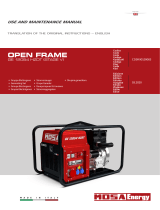
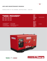
Mase IS 14.5T Usage Manual

Category
Power generators
Type
Usage Manual

This manual is also suitable for

masemase
masemase
mase
GENERATORS
I - MANUALE DI USO E MANUTENZIONE
GB - USAGE AND MAINTANCE MANUAL
F - MANUEL D’INSTRUCTIONS ET D’ENTRETIEN
D - GEBRAUCHSANWEISUNG UND WARTUNGSVORSCHRIFTEN
E - MANUAL USO Y MANTENIMENTO
NL - GEBRUIKS- EN ONDERHOUDSHANDLEIDING
I.S. 14.5T - 20T
50 Hz
REV.1 mc. 05-07-02 cod.42163
IS 14.5T - 20T
2
mama
mama
ma
ss
ss
s
ee
ee
e
MASE GENERATORS S.p.A.
Tel.0547/354311
Fax 0547/317555
NR.000000
DICHIARAZIONE CE DI CONFORMITA'
EC DECLARATION OF CONFORMITY
Fabbricante/Manufacturer: MASE GENERATORS S.p.A.
Indirizzo /Address : Via Tortona 345, Pievesestina (FC)
Il sottoscritto Luigi Foresti in qualità di direttore generale della MASE GENERATORS S.p.A., dichiara sotto la
propria responsabilità che il gruppo elettrogeno modello ......... :
The undersigned Luigi Foresti as MASE GENERATORS S.p.A. general manager declares, under his sole
responsability, that the generators model is..................:
Codice / Code Descrizione / Model Matricola / Serial N.
E' conforme alle disposizioni delle Direttive di seguito elencate :
CEE 89/392 (come emendata delle Direttive CEE 91/368 e CEE 93/44)
CEE 89/336 (come emendata delle Direttive CEE 92/31)
CEE 73/23 modificata da CEE 93/68.
Corresponds to the requirements of the following EEC Directives :
89/392/EEC (as amended by the Directive 91/368/EEC and 93/44/EEC)
89/336/EEC (as amended by the Directive 92/31/EEC )
73/23//EEC as amended by 93/68/EEC.
Cesena, / / ......................................................
Direttore Tecnico
Technical Director
GENERATORS
MASE GENERATORS S.p.A. Sede legale ed Amm.: 47023 CESENA (FC) ITALY - Via Tortona, 345 - C.F./P.I. 00687150409 Cap. Soc. milioni
1625 interamente versato - Registro Società Tribunale Forl' n. 6818 - CCIAA Forl' n.164063 - c.c.p. n. 11541471 - EXPORT FO n. 006368
1
IS 14.5T - 20T
mama
mama
ma
ss
ss
s
ee
ee
e
3
2
1
2
3
5
6
7
8
9
4
10
SERIAL No.
IS 14.5T - 20T
4
mama
mama
ma
ss
ss
s
ee
ee
e
3
1
2
3
5
6
7
8
9
21
1112
13
1416 1518
19 20 10
22
26
4
17
23
25 24
27
IS 14.5T - 20T
mama
mama
ma
ss
ss
s
ee
ee
e
5
12
9
8
7
6
10
4
5
12 3 4 5
11
1
3
2
2
45
IS 14.5T - 20T
6
mama
mama
ma
ss
ss
s
ee
ee
e
S.A.E
Service
Grade
-30 -20 -10 0 10 20 30 40
Ambient temperature (
o
C)
40
20W
20W40
20
30
5W
5W30
10W
10W30
7
6
TAB "A"
8
1
2
3
1
2
3
IS 14.5T - 20T
mama
mama
ma
ss
ss
s
ee
ee
e
7
9
10
1
2
1
3
5
4
3
2
IS 14.5T - 20T
8
mama
mama
ma
ss
ss
s
ee
ee
e
11
12
1
2
IS 14.5T - 20T
mama
mama
ma
ss
ss
s
ee
ee
e
9
13
No. FILE: 22.51.089-00
WIRING DIAGRAM
IS 14.5T - 20T
mama
mama
ma
ss
ss
s
ee
ee
e
23
GB
INDEX
Pictures ............................................................................................................. 2
Wiring diagram ................................................................................................. 9
1 GENERAL INFORMATION ................................................................... 24
1.1 Purpose and field of application of the manual ...................................... 24
1.2 Symbols ............................................................................................... 24
1.3 Reference documents ........................................................................... 25
1.4 Facsimile of CE declaration of conformity ............................................. 25
1.5 Reference regulations and legislative provisions .................................... 25
1.6 Machine identification ........................................................................... 25
1.7 Generetors conposition ......................................................................... 26
1.8 Instrument panel ................................................................................... 26
2 GENERATOR CARACTERISTIC .......................................................... 26
2.1 General caracteristic............................................................................. 26
2.2 Cooling system..................................................................................... 26
2.3 Control panel ........................................................................................ 26
2.4.1 Data sheet IS 14.5T ............................................................................. 27
2.4.2 Data sheet IS 20T ................................................................................ 28
3 SAFETY REGULATIONS ..................................................................... 28
3.1 General precautions .............................................................................. 28
3.2 Prescriptions for safety during installation and setup ............................ 29
4 USINS THE GENERATOR .................................................................... 29
4.1 Preliminary checks ............................................................................... 29
4.2 Bleeding the fuel system ...................................................................... 29
4.3 Starting ................................................................................................. 29
4.4 Stopping ...............................................................................................29
5 PROTECTIONS .................................................................................... 30
5.1 Low oil pressure protection ................................................................... 30
5.2 High water temperature protection ........................................................ 30
5.3 Alternator overheating protection ........................................................... 30
5.4 Protection against short-circuit and overload ........................................ 30
5.5 Protection against short-circuit of the low-voltage electric system ........ 30
6 MAINTENANCE .................................................................................... 30
6.1 Preamble .............................................................................................. 30
6.2 Ordinary engine maintenance ............................................................... 31
6.3 Engine oil and oil filter change .............................................................. 31
6.4 Air filter cleaning ................................................................................... 31
6.5 Fuel filter replacement .......................................................................... 31
6.6 Coolant check ...................................................................................... 31
6.7 V-belt tension check ............................................................................. 32
6.8 Emptying the cooling system ............................................................... 32
6.9 Coolant replacement ............................................................................. 32
6.10 Zinc anode replacement ........................................................................ 32
6.11 Seawater pump maintenance ............................................................... 32
6.12 Alternator maintenance ......................................................................... 32
6.13 Battery maintenance ............................................................................. 33
6.14 Periods of inactivity ............................................................................... 33
6.15 Table of scheduled maintenance ........................................................... 33
6.16 Troubleshooting .................................................................................... 33
7 TRANSPORT AND HANDLING ............................................................ 34
8 SCRAPPING ........................................................................................ 34
9 WIRING DIAGRAM REFERENCES ...................................................... 34
IS 14.5T - 20T
24
mama
mama
ma
ss
ss
s
ee
ee
e
GB
FAILURE TO RESPECT THE SPECIFICATIONS CONTAINED IN THIS USE AND MAINTENANCE
MANUAL WILL RESULT IN FORFEITURE OF THE GUARANTEE ON THE PRODUCT
1 GENERAL INFORMATION
Carefully consult this manual before proceeding with any operation on the generator.
1.1 Purpose and field of application of the manual
Thank you for choosing a mase product.
This manual has been drawn up by the manufacturer with the purpose of providing essential information and instructions
for proper use and maintenance in conditions of safety and constitutes an integral part of the generator equipment.
The manual must be kept safely, protected from any agent which might damage it, for the entire life of the generator
and must accompany the generator if transferred to another user or owner.
The information contained in the manual is addressed to all those persons involved in the operating life cycle of
the generator, and is necessary to inform both those who effectively carry out the different operations and those
who coordinate the activities, arrange the necessary logistics and regulate access to the place where the
generator will be installed and operated.
The manual defines the purpose for which the generator was constructed and contains all the information necessary
to guarantee safe and proper use.
Constant observance of the instructions contained in this manual guarantees the safety of the operator, operating
economy and a longer life of the generator.
It is warmly recommended to carefully read the contents of this manual and the reference documents; only thus
can regular functioning and reliability of the generator be guaranteed over time, and protection against damage to
persons or things.
The drawings are provided by way of example. Even if the generator in your possession differs considerably from the
illustrations contained in this manual, the safety of the generator and the information provided are nevertheless
guaranteed.
To facilitate consultation, it has been divided into sections identifying the main concepts; for a quick look at the
topics, consult the index.
Note: the information contained in this publication is correct at the time of printing. The manufacturer in his pursuit
of a policy of constant development and upgrading of the product reserves the right to make modifications without
prior notice.
1.2 Symbols
Those parts of the text not to be ignored are highlighted in bold type preceded by a symbol, as illustrated and defined
below.
Indicates that particular attention must be paid in order to prevent running into serious danger
which could lead to death or possible hazards to the health of personnel.
A condition which may occur during the lifetime of a product, system or plant considered at
risk regarding damage to persons, property, the environment or economic loss.
Indicates that particular attention must be paid in order to prevent serious consequences which
could result in damage to tangible goods, such as the resources or the product.
Instructions of particular importance.
IS 14.5T - 20T
mama
mama
ma
ss
ss
s
ee
ee
e
25
GB
1.3 Reference documents
The instructions for use provided with each generator
are made up of a collection of documents of which this
manual represents the General Part.
Normally, the following documents are provided:
a - CE declaration of conformity.
b - Instruction manual for use and maintenaqnce of the
generators (this manual).
c - Installation manual of the generators.
d - Wiring diagrams of the control panels and power
board.
e - Engine use and maintenance manual
f - Alternator use and maintenance manual
g - Any other manuals for the optional accessories
issued by the respective manufacturers.
h - List of Mase Service Centres
i - Certificate of guarantee
l - Guarantee card
1.4 Facsimile of CE declaration of conformity
The generators constructed by mase, intended for
countries in the European Community, are in
conformity with the applicable EEC Directives (see
1.5) and are furnished with an EC declaration of
conformity (Fig. 1).
EN 60439-1 (CEI 17-13/1): Assembled protection and
manoeuvring equipment for low voltage (low-voltage
panels).
EN 50081-1/2 (Electromagnetic compatibility):
General regulation on emission
– Part 1: Residential, commercial and light-industry
environments.
- Part 2: Industrial environment.
EN 50082-1/2 (Electromagnetic compatibility):
General regulation on immunity.
- Part 1: Residential, commercial and light-industry
environments.
- Part 2: Industrial environment.
89/392/EEC and subsequent amendments contained
in the Directives 91/368/EEC, 93/44/EEC and 93/68/
EEC: Essential machine requirements for safety and
health protection (“Machine” directive).
73/23/EEC and subsequent amendments contained in
the Directive 93/68/EEC: Guarantee of safety of
electrical material intended for use within certain
voltage limits (“Low Voltage” directives).
1.5 Reference regulations and legislative
provisions
All the mase diesel generators are designed and
manufactured in compliance with the legislation in force.
The generator and its components are constructed in
accordance with the following applicable regulations and
directives:
EN 292-1/2: Machine safety regulations.
General design principles.
EN 294: Machine safety regulations.
Safety distances to prevent contact of dangerous
parts with the upper limbs.
ISO 3046: Alternate internal-combustion engines.
IEC 34-1: Rotary electric machines.
ISO 8528-1: Alternate current generators driven by
alternate internal-combustion engines.
EN 60204-1 (CEI 44-5):
- Machine safety.
- Electrical equipment of machines.
1.6 Machine identification
See Fig.2
1 - Manufacturer
2 - Machine code
3 - Year of construction
4 - Power factor
5 - Declared frequency
6 - Continuous power
7 - Rated voltage
8 - Rated current
9 - Weight
10 – Serial number
The machine code number, the serial number and
the year of construction must always be quoted
when contacting the manufacturer for information,
requests for spare parts, etc.
IS 14.5T - 20T
26
mama
mama
ma
ss
ss
s
ee
ee
e
GB
2. GENERATOR CARACTERISTIC
2.1 General caracteristic
The IS generators were designed for easy installation on
boats.
The soundproof casing, obtained with insulated, painted
marine aluminium panels, allows easy access to the
engine and the alternator for maintenance and inspection
operations, and at the same time strongly reduces noise.
The 4-stroke, direct-injection, diesel engine, built by
Yanmar, is extremely reliable and robust. Exhaust
emission is in conformity with CARB regulations.
The synchronous-type, 4-pole, brushless alternator has
an electronic voltage regulator (SR7) which guarantees
stability to + 5% with respect to the nominal value. The
high pickup capacity of the alternator makes the generator
particularly suitable for the power supply of electric
motors of air conditioners, desalination plants,
compressors, etc.
The generator has a local control panel [Fig. 3 Ref. 4] on
which the controls and control instruments are housed.
2.2 Cooling system
The generator engine is cooled by closed-circuit circulation
of coolant which yields heat to the seawater by means of
a heat exchanger [Fig. 3, Ref. 20].
This heat exchanger built of cupronickel was specially
designed by mase to make the engine suitable for use
at sea.
A second heat exchanger cools the air inside the
soundproof casing and the air necessary for alternator
ventilation.
At the time of installation a seawater feed circuit for
cooling must be installed and an exhaust system to
convey the combustion gas and the water used for
cooling to the outside, as indicate in the installation
manual.
2.3 Control panel
A control panel is positioned on the generator for running
checks and to start and stop the generator. An engine
protection module [Fig. 4 Ref. 5] controls the generator
protections, stopping the engine in case of a fault and
signalling the fault detected by means of special warning
lights.
- Green “RUN” pilot light [Fig. 4 Ref. 6], when on,
indicates that the generator is running and no operating
fault has been detected.
- Red “BATT” pilot light [Fig. 4 Ref. 9), when on,
indicates that the alternator battery charger is faulty.
- Red “OIL” pilot light [Fig. 4 Ref. 7], when on, indicates
that the engine oil pressure is insufficient.
- Red [Fig. 4 Ref. 10] pilot light, when on, indicates
1.7 Generetors conposition
See Fig.3
The generators are essentially composed of the
following components:
1- Soundproof casing
2- Top access door
3- Side access door
4- Instrument panel
5- Anchoring brackets
6- Exhaust and cooling water pipe fitting
7- Seawater intake connection pipe fitting
8- Connection pipe fittings to fuel tank
9- Connection terminals to battery
10- Engine air filter
11- Coolant expansion tank
12- Engine oil extraction pump
13- Diesel fuel filter cartridge
14- Seawater pump
15- Fuel pump A.C.
16- Oil filter cartridge
17- Oil fillercap
18- Electric line connection box
19- Battery charger alternator
20- Coolant tank
21- Water/air heat exchanger
22- Exhaust manifold
23- Starter motor
24- Fuel cock
25- Remote control panel connector
26- RPM adjusting screw of engine
1.8 Instrument panel
See Fig.4
Each generators is fitted with an instrument panel for
the controls with the following components
1- Hour counter
2- Magnetothermal switch
3- DC current thermal switch
4- START/STOP-Preheat button
5- Engine protection module
6- “RUN” light – engine running
7- “OIL” light – low oil pressure
8- “ºC” light – high engine temperature
9- “BATT” light – battery charger operating
10- “ºC” light – high alternator temperature
11- Preheat ligh - (not present)
12- Fuel leak (version “RINA”)
IS 14.5T - 20T
mama
mama
ma
ss
ss
s
ee
ee
e
27
GB
that the temperature of the coolant or the water
circulating in the heat exchangers is too high.
- Red [Fig. 4 Ref. 8] pilot light, when on, indicates that
the alternator windings have reached too high
temperatures.
- Yellow [Fig.4, Ref.11] pilot ligh,when on, indicates
that the glow plugs are active.
The following may also be found on the control panel:
- A bipolar magnetothermal switch [Fig. 4 Ref. 2]
which cuts the power in case of an overload or short-
circuit.
- A thermal switch (Fig. 4 Ref. 3] to protect the low-
voltage electric system against short-circuit.
- An hour counter (Fig. 4 Ref. 1].
- The generator start/stop button [Fig. 4 Ref. 4].
The generator can be connected with a connector to the
remote starting panel, supplied by mase as an optional,
and can be installed on the dashboard.
Two different remote starting panels are available as
shown in Fig. 5.
The most simple version has a start/stop button [Fig. 5
Ref. 1] and a green pilot light [Fig. 5 Ref. 2] which, when
on, indicates that the generator is running.
The second version of the remote starting panel [Fig. 5
Ref. 3] has, in addition to the start/stop button, an
instrument which indicates the engine oil pressure value
(Fig. 5 Ref. 4] and an instrument which indicates the
coolant temperature value [Fig. 5, Ref. 5].
When carrying out maintenance
operations on the generator, disconnect the negative
pole of the starter battery to prevent accidental
starting.
2.4.1 Data sheet IS 14.5T
ENGINE
Model
Type
C
y
linders
(
nr.
)
Cylinder block material
Bore
(
mm. - in.
)
Stroke (mm.- in.)
Dis
p
lacement
(
cc. - CID
)
Power (hp)
RPM
Compression ratio
Combustion s
y
stem
Engine head material
S
p
eed
g
overno
r
Lubrication system
Oil sum
p
ca
p
acit
y
with filter
(
l -
g
l
)
Engine stop system
Fuel pump
Fuel
p
um
p
dischar
g
e
(
cm. - ft
)
Fuel consumption (l/h - gl/h)
A
ir intake
(
l/min. -
g
l/min.
)
Starting battery (Ah-V)
Batter
y
char
g
er
(
Ah-V
)
Starter
(
KW-V
)
Max. inclination
Water
p
um
p
flow
(
l/min. -
g
l/min.
)
ALTERNATOR
Type
Re
g
ulation
Coolin
g
Volta
g
e 3~
(
V
)
Fre
q
uenc
y
(
Hz
)
Max. power (Kw - kVA)
Continuous
p
ower
(
Kw - kVA
)
Power factor ( cos ø )
Insulatin
g
class
Voltage stability
Fre
q
uenc
y
stabilit
y
50
11.2-14.1
10.2-12.7
25 - 5.4
50 Hz
30°
Mechanical
50 Hz
400
18.1
1500
4 - 0.88
1100 - 241
80 - 12
40 - 12
1.2 - 12
Yanmar 3TNE88A
Diesel 4 stroke
3
Cast iron
88 - 3.46
90 - 3.5
1642 - 100.2
80 - 2.62
4.8 - 1
Cast iron
Centrifugal mechanical
Stop solenoid
Forced
18:1
Direct injection
Synchronous, 4-poles,
brush less self-excited
H
±2%
±5%
Air/water ( Intercooler W/A )
1-0.8
Electronic
IS 14.5T - 20T
28
mama
mama
ma
ss
ss
s
ee
ee
e
GB
2.4.2 Data sheet IS 20T 3 SAFETY REGULATIONS
3.1 General precautions
Before starting the generator and before starting any
lubrication or maintenance operation, it is indispensable
for the staff responsible to read and understand all the
WARNINGS and all the CAUTION and DANGER
indications listed in this manual and in the supplementary
documentation furnished.
Nevertheless, the manufacturer cannot foresee all the
possible circumstances which may lead to potential
risks in the effective conditions of use of the generator.
Any operations and/or procedures for maintenance not
expressly recommended or indicated in the user manuals
must always be notified to and approved by the
manufacturer.
In the event that a procedure not specifically
recommended needs to be applied, the user is
responsible for assuring that such procedure is safe and
does not cause harm to persons or things.
The manufacturer declines all responsibility for damage
to persons or things deriving from inobservance of the
safety regulations.
Carefully examine the safety warning plates on the
machine and respect the relevant instructions.
- Do not permit incompetent persons or without
adequate training to use the generator.
- Do not permit children or animals to approach the
generator when it is in operation.
- Do not access the generator with wet hands, since it
is a potential source of electric shock if improperly
used.
- Any inspections of the generator must be carried out
with the engine off. Inspections with the engine on are
to be carried out by specialised personnel only.
- Do not inhale the combustion smoke since it contains
substances hazardous to health.
- Use the generator with the access doors closed.
- Never touch the engine or alternator body with the hands
when the generator is running or still hot.
- When carrying out maintenance operations on the
generator, disconnect the negative pole of the
starter battery to prevent accidental starting.
- In the event of oil or fuel leaks, clean off thoroughly
to prevent creating fire hazard conditions.
- In the event of fire, use a homologated fire
extinguisher – never use water.
- Do not allow access to persons wearing a
pacemaker because of possible electromagnetic
interference with the device.
Should any problem arise or
should you have any questions, please contact the
Mase SERVICE department.
ENGINE
Model
Type
C
y
linders
(
nr.
)
Cylinder block material
Bore
(
mm. - in.
)
Stroke (mm.- in.)
Displacement
(
cc. - CID
)
Power (hp)
RPM
Compression ratio
Combustion system
Engine head material
Speed governor
Lubrication system
Oil sump capacity with filter(l -gl)
Engine stop system
Fuel pump
Fuel pump dischar
g
e
(
cm. - ft
)
Fuel consumption (l/h - gl/h)
Air intake
(
l/min. -
g
l/min.
)
Starting battery (Ah-V)
Batter
y
char
g
er
(
Ah-V
)
Starter (KW-V)
Max. inclination
Water pump flow (l/min. - gl/min.)
ALTERNATOR
T
y
pe
Voltage regulation
Coolin
g
Voltage 3~ (V)
Frequenc
y
(
Hz
)
Power factor ( cos ø )
Max. power
(
kW - kVA
)
Continuous power (kW - kVA)
Insulatin
g
class
Voltage stability
Frequenc
y
stabilit
y
13.9 - 17.4
50 Hz
24.1
1500
80 - 2.62
Electronic
30°
80 - 12
40 - 12
1.2 - 12
5.6 - 1.23
1500 - 328
25 - 5.4
50 Hz
Yanmar 4TNE88A
Diesel 4 stroke
4
Cast iron
88 - 3.46
90 - 3.5
2190 - 133.6
18:1
Direct injection
Mechanical
5.8 - 1.27
Cast iron
Centrifugal mechanical
Fuel solenoid
Forced
Synchronous, 4-poles, self-excited
H
±2%
±5%
Air/water ( Intercooler W/A )
1 - 0,8
400
50
15.3 - 19.1
IS 14.5T - 20T
mama
mama
ma
ss
ss
s
ee
ee
e
29
GB
When using the generator al-
ways bear in mind that in wet or very humid
places and in confined conduction spaces it is ob-
ligatory to comply with articles 313 and 318 of
Presidential Decree No. 547 27/04/55, as well as
Chap. 11 Section IV of the CEI 64-8 regulation.
3.2 Prescriptions for safety during installation and
setup
- The personnel in charge of installation and starting
of the generator must always wear a protective
helmet, safety shoes and overalls.
- Use protective gloves.
- Do not leave disassembled parts, tools or
anything else not forming part of the system on
or near the engine.
- Never leave inflammable liquids or cloths soaked
in inflammable liquids in proximity of the
generator, near electric equipment (including
lamps) or parts of the electrical system.
- Take the necessary precautions to prevent the
danger of electrocution.
- Check that the earthing system has been installed
and constructed in accordance with regulations.
4 USING THE GENERATOR
4.1 Preliminary checks
Before beginning with any starting procedure, it is
extremely important to become “familiar” with the
generator and its controls. Furthermore, a visual
inspection must be carried out on the machine and the
installation.
Any source of potential or real danger must be eliminated
before proceeding.
· Identify the position of the emergency stop buttons,
switches and other emergency systems on the
generator.
· Learn the special emergency procedures relative to
the installation in question.
- the oil level by means of the dipstick [Fig. 7 Ref. 2] (see
table “A” for recommended oils [Fig. 8]).
- that all the anchoring points of the generator are
properly tightened.
- that all the electrical utilities are off to prevent starting
the generator on load
- that the water and fuel pipes are properly connected
- that all the electrical connections have properly been
carried out and that there are no electrical connections
in a bad state.
- that the water cock is open [Fig. 6 Ref. 2]
- that the section of the water circuit from the pump to the
valves has been filled manually if a non-return valve has
been mounted on the sea intake (as recommended in
the installation manual) [Fig. 4 Ref. 1].
4.2 Bleeding the fuel system
The presence of air bubbles in the fuel system is caused
by irregular functioning of the engine or the incapacity to
reach the nominal number of revolutions. Air might enter
the fuel circuit through a not perfectly tight seal (pipes,
filters, tank) or when the fuel in the tank is at minimum
level. The fuel system has been designed in such a way
as to autonomously eliminate air bubbles that have
penetrated the circuit.
To eliminate the air bubbles, first of all eliminate the cause
and carry out the following operations:
1- Adjust the AC fuel pump lever manually [fig.7, ref.3]
until all the air in the supply system has been released.
2- Repeat the operations described above if engine
operation is still irregular.
For more detailed information,
consult the manual supplied by the engine
manufacturer that accompanies each generator .
4.3 Starting
Before starting the generator, ensure that the preliminary
checks described in paragraph 4.1 have been carried
out.
Start the generator by pressing the START button located
on the control panel [Fig. 4 Ref. 4] and release it only
when the generator has started, taking care not to
exceed 15 sec. for each attempt and respecting an
interval of at least 30 sec. All the warning lights of the
engine protection module [Fig. 4, Ref. 5] will come on for
a few seconds, and if there are no engine or generator
faults, only the green RUN light [Fig. 4 Ref. 6] will remain
on to indicate that the generator has been started and
that functioning is regular.
Repeated attempts at starting with
negative outcome may cause excess accumulation
of water in the exhaust system with possible serious
damage to the engine.
If it is difficult to start the engine, do not insist for too
long without first having closed the sea intake cock
[Fig. 6 Ref. 2].
4.4 Stopping
The generator is stopped by pressing the button [Fig.4,
Ref.4] on the control panel in "STOP"position.
Before stopping the generator it is
recommended to let it run for a few minutes without
drawing electric current, in order to allow the engine
and the alternator to cool down.
IS 14.5T - 20T
30
mama
mama
ma
ss
ss
s
ee
ee
e
GB
5. PROTECTIONS
The generators are equipped with a series of protections
which safeguard it against improper use and faults which
may compromise integrity.
When the generator stops because a protection has
tripped, on the engine protection module [Fig. 5, Ref. 5]
of the control panel the warning light relative to the fault
will come on.
5.1 Low oil pressure protection
Intervenes switching off the generator when the engine oil
pressure is insufficient. Its intervention is signalled by the
“OIL” light [Fig., 4, Ref. 7] coming on. Normally it is
sufficient to top up with the lacking quantity of oil to be
able to restart the generator.
- The low oil pressure protection does not give an
indication of the level of engine oil in the sump.
Therefore, check this level daily.
- The engine functions properly if it does not exceed
an inclination of maximum 30º for less than 3
minutes, 25º without time limit, both on the
longitudinal and the transverse axis. If the engine is
operated at a greater inclination, the risk is
insufficient lubrication or aspiration of engine oil
through the air filter.
5.2 High water temperature protection
Intervenes switching off the generator when the engine
coolant temperature is too high or there is no circulation
of seawater.
Its intervention is signalled by the “ºC” light [Fig. 4, Ref.
10] coming on.
Only restart the generator after the cause of the fault has
been identified and removed.
5.3 Alternator overheating protection
Intervenes switching off the generator when there is a
thermal overload on the alternator.
Its intervention is signalled by the “ºC” light [Fig. 4, Ref.
8] coming on. The generator can be restarted after a few
minutes when the temperature of the alternator windings
has returned to normal values. It is, however,
recommended to find and remove the causes of the
intervention.
In the event of one of the above
described protections intervening, after ascertaining
and removing the cause of the intervention, press the
“STOP” button to reset the control panel (otherwise
the signal would remain in memory preventing the
engine from starting).
5.4 Protection against short-circuit and overload
The generator is protected against short-circuit and
overload. A bipolar magnetothermal switch [Fig. 4 Ref.
2] cuts the supply of electric current when a short-circuit
occurs or when the electric current delivered exceeds the
nominal value.
Before restoring the contact by lifting the lever of the
magnetothermal switch, disconnect the utilities.
5.5 Protection against short-circuit of the low-
voltage electric system
In the event of a short-circuit in the low-voltage electric
system, a thermal switch [Fig. 4, Ref. 3] breaks the
circuit stopping the generator. In this case the warning
lights of the engine protection module will all be off and
it will not be possible to re-attempt starting.
Before restoring the electric circuit by pressing the
button located on the thermal switch [Fig. 4 Ref. 3], have
a specialised technician find and remove the cause of the
short-circuit.
6 MAINTENANCE
6.1 Preamble
Any maintenance operation on
the generator must be carried out with the engine off
and leaving it to cool down sufficiently, and must
only be carried out by authorised and suitably trained
personnel.
It is recommended to scrupulously follow the instructions
in the manual provided by the engine Manufacturer with
each generator.
It is important to regularly inspect and carry out
maintenance on the generator. The frequency of
maintenance should be decided on the basis of the
number of hours of operation.
To proceed with maintenance the side and top doors
must be removed.
Before accessing the generator,
disconnect one pole of the starter battery in order to
prevent accidental starting.
6.2 Ordinary engine maintenance
The periodic maintenance to be carried out on the engine
is listed in TABLE “B”.
For more detailed information consult the manual provided
with each generator by the engine manufacturer.
IS 14.5T - 20T
mama
mama
ma
ss
ss
s
ee
ee
e
31
GB
Check the oil level by means of the
graduated dipstick [Fig. 7, Ref. 2]. The level must
always be between the MAX and MIN notches on the
dipstick [Fig. 7 Ref. 1].
6.3 Engine oil and oil filter change
The engine oil sump capacity is 2.3 litres.
Top-ups and filling with engine oil is carried out through
the hole [Fig. 3, Ref. 17].
To change the oil in the oil sump, remove the dipstick
[Fig. 7, Ref. 2] and operate the special extraction pump
[Fig. 3, Ref. 12] after having removed the screw which
functions as plug.
It is recommended to drain the oil when it is still
sufficiently warm to flow easily.
For recommended oils see table “A”, Fig. 8.
- The first engine oil change must be carried out after
50 hours of generator operation. For the second
and subsequent oil changes, every 200 hours is
sufficient.
- For more detailed information on engine lubrication,
consult the engine use and maintenance manual
attached to the generator.
- Dispose of the used oil or fuel in an appropriate
manner as they are polluting products.
Take the used engine oil to special collection
centres responsible for disposal.
Avoid contact of engine oil with
the skin. During maintenance operations use gloves
and protective glasses.
In case of contact with engine oil, immediately and
thoroughly wash the affected part with soap and
water.
To replace the engine oil filter cartridge [Fig. 3, Ref.16],
unscrew it from its support, using suitable tools normally
found on the market. Reposition the new cartridge,
taking care to lubricate the rubber ring gasket.
The first replacement must be carried out after 50 hours
of generator operation. For the second and subsequent
replacements, respect an interval of 400 hours.
For further information consult the engine use and
maintenance manual.
For the safety of the engine, use
only original spare parts.
When the operation has been
completed, thoroughly wipe off all oil and fuel from
the engine parts.
6.4 Air filter cleaning
The generators of the IS series have a dry air filter which
prevents foreign bodies from entering the combustion
chamber. For its maintenance it is sufficient to clean the
filtering mass with diesel fuel once a year to remove nay
impurities.
Dispose of the liquids used for air
filter washing in an appropriate manner. Take them
to special collection centres.
6.5 Fuel filter replacement
To guarantee long life and proper functioning of the
engine, it is extremely important to periodically replace
the fuel filter cartridge, respecting the frequency indicated
by the engine manufacturer as listed in the table in
Paragraph 6.15.
This operation is carried out in the following steps:
- Close the fuel cock [Fig. 3, Ref. 24]
- Completely unscrew the ring nut of the support [Fig. 3,
Ref. 13]
- Remove the old cartridge and position the new one.
- For remounting repeat the operations in reverse order.
When the filter has been replaced, bleed the fuel system
carrying out the operations described in Paragraph 4.2.
Avoid contact of the fuel oil with
the skin. During maintenance operations use gloves
and protective glasses.
In case of contact with fuel, immediately and
thoroughly wash the affected part with soap and
water.
When the operation has been
completed, thoroughly wipe off all traces of fuel and
take the used cloths to special collection centres.
6.6 Coolant check
Periodically check the coolant level in the closed-circuit
cooling system. The reference index for this check is
printed on the expansion tank [Fig. 3, Ref. 11]. If the level
is insufficient, pour coolant into the expansion tank,
taking care not to exceed the maximum level index.
Never open the cap of the
expansion tank [Fig. 3, Ref. 11] or coolant tank [Fig.
3, Ref. 20] when the engine is hot to prevent
dangerous coolant leaks.
IS 14.5T - 20T
32
mama
mama
ma
ss
ss
s
ee
ee
e
GB
6.7 V-belt tension check
A V-belt is used to transmit the rotary motion from the
drive shaft pulley to that of the seawater pump [Fig. 9 Ref.
1].
Excessive belt tension accelerates wear, while a slack
belt makes the pulleys idle and does not allow sufficient
water circulation.
Adjust the belt tension as follows:
Loosen the two adjusting screws [Fig. 9, Ref. 2] and
move the seawater pump outwards to increase the
tension or inwards to decrease it. Lock the screws and
check the tension.
The correct belt tension is such as to allow a yield of
about 5 mm [Fig. 9] under a thrust force of 8 kg.
A second belt is used to transmit the rotary motion from
the drive shaft pulley to that of the closed-circuit coolant
pump and the battery charger DC alternator [Fig. 9 Ref.
3].
Adjust the belt tension as follows:
Loosen the adjusting screw [Fig. 9 Ref. 4] and move the
battery charger DC alternator [Fig. 9, Ref. 5] outwards to
increase the tension and inwards to decrease it.
The correct belt tension is such as to allow a yield of
about 10 mm [Fig. 9] under a thrust force of 8 kg.
To prevent the belt from slipping,
do not dirty it with oil. Clean the belt with petrol if any
oil is spilled.
Keep hands away from the V-belt
or the pulleys when the engine is running.
6.8 Emptying the cooling system
To carry out maintenance on the water/air exchanger or
on the cooling system the seawater must be drained
from the intake circuit. This operation is carried out as
follows:
- Close the sea intake cock [Fig. 6, Ref. 2]
- Open the drain tap [Fig. 6, Ref. 3] until all the water
has run out
- Close the drain tap.
Reopen the seawater intake cock
before starting the generator.
6.9 Coolant replacement
Annually replace the coolant in the closed cooling circuit
as follows:
- Remove the lower door (Fig.10, Ref.2) by unscrewing
the retaining screws (Fig.10, Ref.3).
- Take a rubber hose of about 50 cm long with an inside
diameter of 30-40 mm.
- Insert the hose through the lower slit, position it under
the cap (Fig.10, Ref.1) and connect it to the inside of a
container of about 10 litre capacity.
- Open the cap and completely drain the closed cooling
circuit.
When the operation has been completed, close the cap
and fill the circuit with new coolant.
Dispose of the used coolant in an
appropriate manner as it is a polluting product.
Take the used coolant to special collection centres
responsible for disposal.
6.10 Zinc anode replacement
To protect the water/air heat exchanger [Fig. 11, Ref. 1]
and the water/coolant heat exchanger [Fig. 11, Ref. 2]
against galvanic current, two sacrificial zinc anodes [Fig.
11, Ref. 4] have been inserted inside them. Periodically
check their state of wear and, if necessary, replace them
in order to prevent that the galvanic current irreparably
corrodes the heat exchanger. It is recommended to
check the zinc anodes at least once a month when the
generator is new to check how fast consumption is, to
then be able to act accordingly.
It is, however, opportune to replace the zinc anodes at
least once a year.
Fig. 11 shows the points where the zinc anodes are
positioned.
6.11 Seawater pump maintenance
At least once a year check the integrity of the rubber rotor
of the seawater pump [Fig. 12, Ref. 1].
Before opening the seawater pump to inspect the rotor,
drain the seawater from the cooling system as described
in Paragraph 6.8.
To access the rotor, remove the cover [Fig. 12, Ref. 2]
and with the aid of a pair of pliers extract the rotor pulling
it out with force.
To remount a new rotor, repeat the operations described
above in reverse order.
6.12 Alternator maintenance
The alternator used on this model of generator is type
synchronous, self-energised, with electronic voltage
regulation. This model alternator, without manifold and
brushes, does not require particular maintenance
operations. The periodic checks and maintenance are
limited to removing any traces of damp and oxidation
which might damage it.
IS 14.5T - 20T
mama
mama
ma
ss
ss
s
ee
ee
e
33
GB
6.13 Battery maintenance
For starting all the generator models, it is recommended
to use an 70 A/h battery for ambient temperatures
exceeding 0ºC, and 100 A/h for lower temperatures.
Before installing a new battery it is important that it
undergoes a full charging cycle.
At least once a month check the level of the electrolyte
and, if necessary, top up with distilled water. If the
generator is not to be used for a long period, it is
recommended to disconnect the battery and store it in a
dry place at a temperature over 10ºC and to carry out a
full charging cycle once a month.
If the battery is left completely flat
for long periods, there is a risk of irreparably damaging
it.
The positive terminal of the battery must be protected
with Vaseline to prevent corrosion and the formation of
oxide.
For top-ups with sulphuric acid,
ready solutions must be used.
The battery top-up operations with
distilled water or with acid must be carried out with
rubber gloves and protective glasses to prevent
accidental contact of the sulphuric acid with the
skin.
In the event of accidental contact, thoroughly wash
the part affected with soap and water and consult a
doctor.
Before recharging the battery
check the level of the electrolyte and, if necessary, fill
up with distilled water. This operation must be
repeated when the recharging cycle has been
completed.
6.14 Periods of inactivity
Start up the generator at least once a month.
If the generator is not to be used for a long time, the
following operations must be carried out:
- Change the engine oil
- Replace the oil filter cartridge (see par. 6.3)
- Replace the fuel filter cartridge (see par. 6.5)
- Remove the injectors and pour 2 cc engine oil into
each cylinder and let the engine turn over a few times,
manually operating the drive shaft pulley. Remount the
injectors.
- Replace the zinc anodes (see par. 6.10)
- Through the seawater intake pipe aspirate some anti-
freeze whose function is to protect the heat exchangers
against low temperatures and to lubricate the seawater
pump rotor and the metallic parts in the cooling
system.
- Disconnect the starter battery and store it in a dry
place (see par. 6.13)
- Disconnect the sea exhaust pipe from the engine
manifold.
- Clean the seawater filter.
- Close the seawater intake cock.
- Drain the seawater from the exhaust.
- Clean and lubricate the antisiphon valve, if installed
(siphon break).
6.15 Table of scheduled maintenance
OPERATION HOURS
Check engine oil level .............................................. 10
Check coolant .......................................................... 10
Check for oil leaks ................................................... 20
Check for fuel leaks................................................. 20
Check for coolant leaks .......................................... 20
Adjust V-belt tension .............................................. 100
Check battery charger ........................................... 100
Clean fuel filter ........................................................ 200
Adjust belt tension .................................................. 200
*Change engine oil .................................................. 200
Check seawater pump rotor .................................. 400
Check engine rpm ................................................... 400
Check integrity of electrical connections ............ 400
Replace fuel filter .................................................... 400
* Replace oil filter .................................................... 400
Check injectors ....................................................... 400
Check injector timing ............................................. 400
Adjust play on intake/exhaust valve ...................... 400
Check the fuel injection pump .............................. 1000
Check battery electrolyte level ...........................monthly
Clean and deoxidise the metallic parts .............. yearly
Clean air filter ........................................................ yearly
Replace coolant completely ................................. yearly
Replace zinc anodes ............................................ yearly
Carry out the first maintenance operation after 50
hours, subsequently according the required intervals.
6.16 Troubleshooting
The starter motor turns but the main engine does
not start
- Check that there is fuel in the tank (fill up)
- Check if the stop electromagnet is in the firing position
(consult Service Centre)
- Bleed the air bubbles from the fuel circuit (see par. 4.2)
The engine protection module is not activated
when the START button is pressed
- battery, and the electrical connections (reconnect).
- Check integrity of the battery (recharge or replace).
The generator switches off during the operating
period
- Check if a protection has been activated with the
TABLE “B”
  • Page 1 1
  • Page 2 2
  • Page 3 3
  • Page 4 4
  • Page 5 5
  • Page 6 6
  • Page 7 7
  • Page 8 8
  • Page 9 9
  • Page 10 10
  • Page 11 11
  • Page 12 12
  • Page 13 13
  • Page 14 14
  • Page 15 15
  • Page 16 16
  • Page 17 17
  • Page 18 18
  • Page 19 19
  • Page 20 20
  • Page 21 21
  • Page 22 22
  • Page 23 23
  • Page 24 24
  • Page 25 25
  • Page 26 26
  • Page 27 27
  • Page 28 28
  • Page 29 29
  • Page 30 30
  • Page 31 31
  • Page 32 32
  • Page 33 33
  • Page 34 34
  • Page 35 35
  • Page 36 36
  • Page 37 37
  • Page 38 38
  • Page 39 39
  • Page 40 40
  • Page 41 41
  • Page 42 42
  • Page 43 43
  • Page 44 44
  • Page 45 45
  • Page 46 46
  • Page 47 47
  • Page 48 48
  • Page 49 49
  • Page 50 50
  • Page 51 51
  • Page 52 52
  • Page 53 53
  • Page 54 54
  • Page 55 55
  • Page 56 56
  • Page 57 57
  • Page 58 58
  • Page 59 59
  • Page 60 60
  • Page 61 61
  • Page 62 62
  • Page 63 63
  • Page 64 64
  • Page 65 65
  • Page 66 66
  • Page 67 67
  • Page 68 68
  • Page 69 69
  • Page 70 70
  • Page 71 71
  • Page 72 72
  • Page 73 73
  • Page 74 74
  • Page 75 75
  • Page 76 76
  • Page 77 77
  • Page 78 78
  • Page 79 79
  • Page 80 80
  • Page 81 81
  • Page 82 82
  • Page 83 83
  • Page 84 84
  • Page 85 85
  • Page 86 86

Mase IS 14.5T Usage Manual

Category
Power generators
Type
Usage Manual
This manual is also suitable for

Ask a question and I''ll find the answer in the document

Finding information in a document is now easier with AI

in other languages