White Rodgers 668-451 Kwik-Sensor CAD Cell Relays User manual
- Category
- Smoke detectors
- Type
- User manual
This manual is also suitable for

WHITE-RODGERS DIVISION
EMERSON ELECTRIC CO.
9797 REAVIS RD., ST. LOUIS, MO. 63123
(314) 577-1300, FAX (314) 577-1517
9999 HWY. 48, MARKHAM, ONT. L3P 3J3
(905) 475-4653, FAX (905) 475-4625
R
Printed in U.S.A.
PART NO. 37-2228E
Replaces 37-2228D
9625
TYPE 668-451
Intermittent Ignition* – Non Recycling
OIL BURNER CONTROL
With Series 956 Flame Detector
(For use with 40VA Cooling Load)
INSTALLATION INSTRUCTIONS
DESCRIPTION
FAILURE TO READ AND FOLLOW ALL INSTRUCTIONS CAREFULLY BEFORE
INSTALLING OR OPERATING THIS CONTROL COULD CAUSE PERSONAL
INJURY AND/OR PROPERTY DAMAGE.
This Type 668 Oil Burner Control provides safe operation
of oil burners on heating plants where ignition during the
entire burner cycle is desired. It is capable of powering
external cooling loads up to 40 VA. A Sub-Base or other
means must be used to prevent heating and cooling
systems from being energized at the same time. The Type
668 is used with the Type 956 Flame Detector.
* Formerly called constant ignition.
PRECAUTIONS
SPECIFICATIONS
INSTALLATION AND WIRING
Operator: Save these instructions for future use!
WHITE-RODGERS
If in doubt about whether your wiring is millivolt, line, or low
voltage, have it inspected by a qualified heating and air
conditioning contractor, electrician, or someone familiar
with basic electricity and wiring.
Do not exceed the specification ratings.
All wiring must conform to local and national electrical
codes and ordinances.
This control is a precision instrument, and should be
handled carefully. Rough handling or distorting compo-
nents could cause the control to malfunction.
To prevent electrical shock and/or equipment
damage, disconnect electric power to system, at
main fuse or circuit breaker box, until installation
is complete.
Do not use on circuits exceeding specified volt-
ages. Higher voltages will damage control and
could cause shock or fire hazard.
CAUTION
!
WARNING
!
ELECTRICAL DATA
Input voltage: 120 VAC, 60Hz.
Maximum Load Current:
Oil Burner Motor (Orange Wire):
10 Amps F.L. 60 Amps L.R.
Ignition Transformer:
360VA (3.0 Amps)
Relay Voltage: 24 Volts AC, 60Hz.
Room Thermostat:
Set adjustable heat anticipator at 0.4 Amps.
Low Voltage Rating (Terminals R&C):
Maximum cooling load of 40VA @ 24v. 60 Hz.
Continuous duty. W & C cycled through thermostat.
Safety Timing: 45 seconds
The proper Location and Mounting of the primary oil
burner control panel on the burner and the flame detector
with respect to the oil flame shall be determined by the
furnace, boiler, or burner manufacturer.
If this control, supplied as part of a furnace, boiler or
burner, is wired to the equipment or if the manufacturer
of such equipment provides instructions for wiring this
control, then follow his recommendations. If no special
wiring instructions are given, then follow the electrical
connections shown.
For more complicated systems, especially for hot water
heating, consult the manufacturer of the heating plant for
full details of the desired sequence of control operation.

2
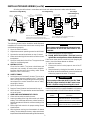
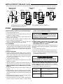
INSTALLATION AND WIRING (cont’d)
HEATING-COOLING THERMOSTAT WITH SWITCHING
SUB-BASE (NOTE: If separate Heating & Cooling
Thermostats are used, SPDT Selector switch must be used.)
*NOTE: HONEYWELL TYPE R8184M USES DUMMY “Y“
AND “G” TERMINALS AS TIE POINTS.
F
F
C
W
RH
RH
W
Y
G
RC
Y*
G*
F
F
C
W
RH
RH
W
Y
G
RC
ORANGE
FLAME
DETECTOR
WIRE
NUTS
INSTALLED
JUMPER
W-R
HEATING-COOLING
THERMOSTAT
W-R TYPE 668-451
WIRING TERMINALS
W-R TYPE 668-451
WIRING TERMINALS
W-R 2-WIRE
HEATING ONLY
THERMOSTAT
IGN.
TRANS.
PRIMARY
CONTROL
WHITE
COOLING
CONTACTOR
FAN RELAY
FLAME
DETECTOR
FLAME
DETECTOR
H-W TYPE R8184M
WIRING TERMINALS
COOLING
CONTACTOR
FAN RELAY
BLACK
LIMIT
LINE
HOT
N
BURNER
MOTOR
F
F
C
W
RH
RH
W
External Line Voltage Wiring
Low Voltage Wiring
Low Voltage
2-Wire Heating Only
All wiring should be done in accordance with local and national electrical codes and ordinances.
TESTING
The following control checks should be made after each
installation to insure that the controls are correctly wired
and functioning properly.
1. Open the main line switch.
2. Adjust thermostat or operating control to call for heat.
3. Operate the manual reset button on top of control.
4. Make certain that high limit control is set at the correct
temperature.
5. Open the hand valve in the oil line. The system is now
ready for the following tests.
A. NORMAL CYCLE:
Close the line switch. The burner should start and
continue to run normally. (If burner starts, establish-
ing flame, but then locks out on safety, make “Flame
Detector Check” at this time.)
B. SAFETY TIMING:
1. Let the burner run for about 5 minutes. Then remove
one of Flame Detector leads from the “F” terminals.
After a time period corresponding to the safety timing
has elapsed, the control should lock out on safety,
stopping the burner.
2. Open the line switch.
3. Replace Flame Detector lead removed in step 1.
4. Wait 3 minutes. Then operate the manual reset button
on top of control.
C. HIGH LIMIT AND THERMOSTAT CHECK:
1. Close the line switch to start the burner.
2. Lower the setting of the high limit control to its lowest
setting. This should stop the burner, unless furnace or
boiler temperature is below the minimum setting of the
high limit.
3. Return high limit control to its proper setting. Burner
should restart.
4. With the burner running, turn thermostat to its lowest
setting. This should stop the burner, unless actual room
temperature is below the lowest setting of the thermostat.
On systems supplying domestic hot water, burner
will continue to run if low limit control is not
satisfied.
5. Return thermostat to its proper setting.
D. FLAME DETECTOR CHECK: (This test is not re-
quired if the control performs as described in test A.)
If the burner starts but the control locks out (stopping the
burner), check the flame detector as follows:
1. Open the line switch.
2. Connect one end of a wire jumper to one of the “F”
terminals.
3. Start the burner by closing the line switch. As soon as
the flame has been established, connect the other end
of the wire jumper to the other “F” terminal.
The control provides NO SAFETY PROTECTION
with this jumper installed. DO NOT leave burner
in this condition except for making this check.
If the control still locks out with the jumper installed, the control
should be replaced. If the control does not lock out, however,
check the operation of the 956 flame detector as follows:
NOTE
WARNING
!
Possible Cause of
Trouble
Open circuit in Cell
Flame detector im-
properly positioned
Replace Cell (or Cell Assembly) of
956 Flame Detector. Do not disturb
position of bracket or socket assembly.
Locate flame detector according to the
burner manufacturer’s specifications.
Correction

3
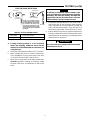
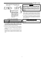
TESTING (cont’d)
Rotate Cell Assembly counter-
clockwise to remove it. To replace
it, insert end through notched open-
ing in bracket and rotate clock-
wise. NOTE: If bracket is ever re-
moved from burner, Cell Assembly
will not fit if bracket is reinstalled
backwards.
TYPE 956 FLAME DETECTORS
OLD STYLE
NEW STYLE
CELL ASSEMBLY
SOCKET
ASSEMBLY
CELL
BRACKET
F063-0485
F063-2006
Cell only (Old Style)
Cell assembly (New Style)
PART No. OF REPLACEMENT PARTS
4. If safety lockout problem is of an occasional
nature the following additional check may be
made to insure that flame detector location is not
a marginal one:
a. Disconnect flame detector leads from “F” terminals.
b. Attach a jumper wire to one “F” terminal. Start burner.
Then immediately connect jumper wire to the other
“F” terminal. Burner should continue to run.
c. With burner running, attach flame detector leads to an
accurate ohmmeter. Reading of ohmmeter should
be below 1000 ohms, and preferably as low as 500
ohms.
If indicator of ohmmeter remains steady, read-
ings up to 2000 ohms should also be acceptable.
Generally, the lower the reading, the better the
application, and less likely the chance of burner
flame variation causing a safety lock-out.
d. If resistance of flame detector is over 1000 ohms, it
may not be able to see the burner flame properly.
Check alignment of the flame detector through the
hole in the static pressure disc. Clean this hole if it is
blocked by foreign matter. Check for broken “F” wires.
e. If flame detector alignment is good but resistance is
still high, readjustment of burner flame and/or nozzle
replacement may be necessary (according to burner
manufacturer’s instructions).
Be sure to remove wire jumper after finishing this
flame detector check.
NOTE
WARNING
!
Page is loading ...
Page is loading ...
Page is loading ...
-
 1
1
-
 2
2
-
 3
3
-
 4
4
-
 5
5
-
 6
6


White Rodgers 668-451 Kwik-Sensor CAD Cell Relays User manual
- Category
- Smoke detectors
- Type
- User manual
- This manual is also suitable for
Ask a question and I''ll find the answer in the document
Finding information in a document is now easier with AI
in other languages
Related papers
-
White Rodgers 668-430 User manual
-
-
-
-
-
-
-
White Rodgers 152-10 Line Voltage, Locked Case User manual
-
-
Other documents
-
Emerson 5C06 User manual
-
UPM THM101B Owner's manual
-
Honeywell RTH2520 Owner's manual
-
Honeywell R8184M User manual
-
Broan RG1 Installation guide
-
 White-Rodgers 36H Installation guide
-
A.O. Smith 100122526 Installation guide
-
-
-
Rodgers Imagine Series 351 Owner's manual
