7
940 watts ÷ 12V = 78 DC Amps
468 Amp-Hours ÷ 40 Amps
Inverter/Charger Rating
= 11.7 Hours Recharge
Example
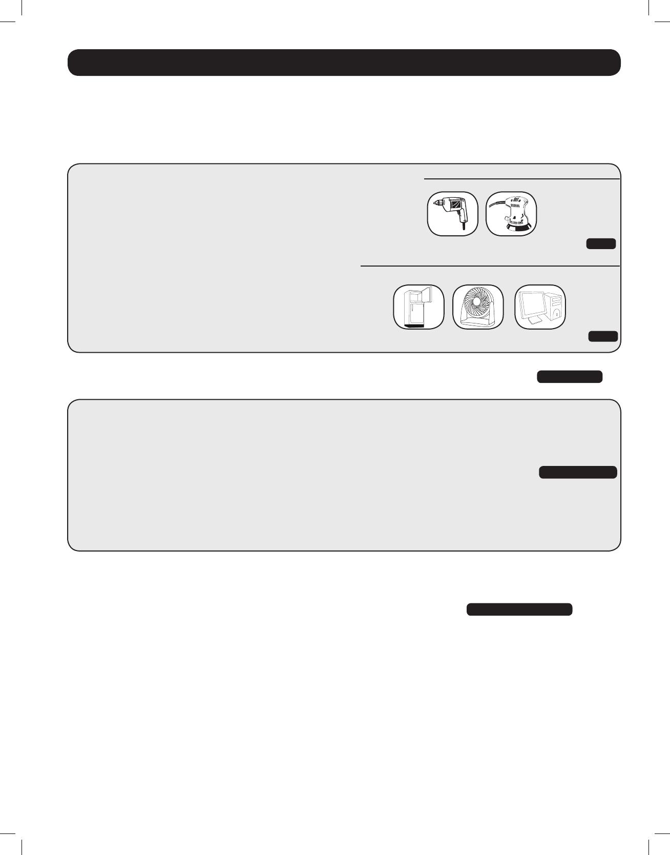
Tools
13mm (1/2”) Drill Orbital Sander
Appliances and Electronics
Desktop Computer with
Refrigerator Table Fan Large LCD Monitor
640W + 220W = 860W
540W + 150W + 250W = 940W
78 DC Amps × 5 Hrs. Runtime
× 1.2 Inefficiency Rating = 468 Amp-Hours
•STEP1)DetermineTotalWattageRequired
Add the wattage ratings of all equipment you will connect to your
Inverter/Charger. Wattage ratings are usually listed in equipment
manuals or on nameplates. If your equipment is rated in amps,
multiply that number times AC utility voltage to estimate watts.
(Example: a drill requires 2.8 amps. 2.8 amps × 230 volts = 640 watts.)
NOTE: Your Inverter/Charger will operate at higher efficiencies at about
75% - 80% of nameplate rating.
•STEP2)DetermineDCBatteryAmpsRequired
Divide the total wattage required (from step 1, above)
by the nominal battery voltage to determine the DC amps required.
•STEP3)EstimateBatteryAmp-HoursRequired
Multiply the DC amps required (from step 2, above) by the number of
hours you estimate you will operate your equipment exclusively from
battery power before you have to recharge your batteries with utility- or
generator-supplied AC power. Compensate for inefciency by
multiplying this number by 1.2. This will give you a rough estimate of
how many amp-hours of battery power (from one or several batteries)
you should connect to your Inverter/Charger.
NOTE: Battery amp-hour ratings are usually given for a 20-hour discharge rate. Actual
amp-hour capacities are less when batteries are discharged at faster rates. For example,
batteries discharged in 55 minutes provide only 50% of their listed amp-hour ratings, while
batteries discharged in 9 minutes provide as little as 30% of their amp-hour ratings.
•STEP4)EstimateBatteryRechargeRequired,GivenYourApplication
You must allow your batteries to recharge long enough to replace the
charge lost during inverter operation or else you will eventually run down
your batteries. To estimate the minimum amount of time you need to
recharge your batteries given your application, divide your required battery
amp-hours (from step 3, above) by your Inverter/Charger’s rated charging
amps (depending on the Switch 6, 7 and 8 ON/OFF settings).
NOTE! For Tripp Lite Inverter/Chargers providing 1000 watts or less of continuous AC
power, a full-size battery will normally allow sufficient power for many applications before
recharging is necessary. For mobile applications, if a single battery is continuously fed
by an alternator at high idle or faster, then recharging from utility or generator power
may not be necessary. For Tripp Lite Inverter/Chargers over 1000 watts used in mobile
applications, Tripp Lite recommends you use at least two batteries, if possible fed by
a heavy-duty alternator any time the vehicle is running. Tripp Lite Inverter/Chargers will
provide adequate power for ordinary usage within limited times without the assistance
of utility or generator power. However, when operating extremely heavy electrical loads
at their peak in the absence of utility power, you may wish to “assist your batteries” by
running an auxiliary generator or vehicle engine, and doing so at faster than normal idling.
3. Battery
3.1.1 Match Battery Amp-Hour Capacity to Your Application
Select a battery or system of batteries that will provide your Inverter/Charger with proper DC voltage and an adequate amp-
hour capacity to power your application. Even though Tripp Lite Inverter/Chargers are highly efcient at DC-to-AC inversion,
their rated output capacities are limited by the total amp-hour capacity of connected batteries and the support of your
vehicle’s alternator if the engine is kept running.
201110117 93-3054.indb 7 11/9/2011 10:57:56 AM