
T1
T2
C
Y
O
W2
R
DFT
E
DF1 DF2
O
LPS
DEFROST CONTROL BOARD
DEFROST
THERMOSTAT
CONTACTOR
LIQUID LINE
SELENOID
COIL (WHEN
REQUIRED)
REVERSING
VALVE
SELENOID
H
S
R
C
S
R
C
CF
T1 T2
L2L1
CCH
COMPRESSOR
DUAL CAPACITOR
OUTDOOR FAN MOTOR
GROUNDING
LUG
SINGLE PHASE
FIELD SUPPLY
YELLOW
YELLOW
RED
BLACK
START
CAPACITOR
START
RELAY
TO T2 ON
CONTACTOR
TO T1 ON
CONTACTOR
TO “H” ON CAPACITOR
2
1
5
OPTIONAL HARD START KIT
BLACK OR BLACK / WHITE
YELLOW OR YELLOW / BLACK
BLUE
ORANGE
RED
BLACK
BLACK
BLACK
RED
RED
YELLOW
BLACK
BLACK
BLACK
BLACK
BLUE
C
L2
T2
R
H
L1
T1
CCH (IF EQUIPPED)
COMPRESSOR
CONTACTS
C
F
DUAL CAPACITOR
LOW VOLTAGE
TERMINALS
COMPRESSOR
OUTDOOR
FAN MOTOR
R
S
S
C
Control
Logic
CC
DFT
RVS
LPS
DFT
DEFROST CONTROL BOARD
DF1
DF2
R
W2
O
Y
C
T1
T2
ODT
R
E
O
Y
C
W2
2
1
1
3
4
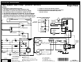
DFT - Defrost Thermostat
RVS - Reversing Valve Solenoid
CC - Contactor Coil
CCH - Crankcase Heater (If Equipped)
ODT - Outdoor Thermostat
(Select Models Only)
Closing during defrost.
Rating: 1 Amp. Max.
Opens during defrost.
Rating: 2 HP at 230 Vac Max.
Closed when "Y" is on.
Open when "Y" is off.
Provides "off" delay time of 5 min. when "Y" opens.
With DFT closed and "Y" closed, compressor run time is
accumulated. Opening of DFT during defrost or interval
period resets the interval to 0.
1
2
3
4
LPS - Low Pressure Switch
* These features are not included on all models.
Defrost Board Operation:
(Note: Five minute delay on power
up or on power interruption)
Split System Heat Pump (Outdoor Section)
NOTES:
1. Disconnect all power before servicing.
2. For supply connections use copper conductors only.
3. Not suitable on systems that exceed 150 volts to ground.
4. For replacement wires use conductors suitable for 105 C.
5. For ampacities and overcurrent protection, see unit rating plate.
6. Connect to 24 vac/40va/class 2 circuit. See furnace/air handler
instructions for control circuit and optional relay/transformer kits.
7. DO NOT install a Hard Start Kit on a model with a PTCR installed.
1. Couper le courant avant de faire letretien.
2. Employez uniquement des conducteurs en cuivre.
3. Ne convient pas aux installations de plus de
150 volt a la terre.
Single Phase
WIRING DIAGRAM
710253A
(Replaces 7102530)
10/08
FIELD WIRING
LEGEND:
LOW VOLTAGE
HIGH VOLTAGE
¢710253x¤
-
 1
1

Westinghouse FT5BD Product information
- Type
- Product information
- This manual is also suitable for
Ask a question and I''ll find the answer in the document
Finding information in a document is now easier with AI
Related papers
-
Westinghouse CSH4BE Installation guide
-
-
-
Westinghouse MT4(B,Q)D Archived 11/21/2011 Installation guide
-
-
Broan FT4BE Product information
-
-
Broan 1-Phase Split System Heat Pump WD Product information
-
-
Other documents
-
Reznor JS4BD Product information
-
Gibson JT4BD Product information
-
Unbranded T3BN 7.5 - 10 Product information
-
Gibson DT5BD Product information
-
Intertherm S(T)4BX Product information
-
Reznor JT4BE Installation guide
-
-
-
Nordyne T3BN 7.5 - 10 User manual
-