Page is loading ...

Turbo Carnival
Clubhouse
Carnival
Clubhouse
COPYRIGHT 2017 RAINBOW PLAY SYSTEMS, INC. ALL RIGHTS RESERVED
RAINBOW RESERVES THE RIGHT TO MAKE CHANGES AND MODIFICATIONS TO THIS PRODUCT.
!
Carnival Clubhouse
Assembly Instructions
5-70-0424
(Rev 1 -3/7/17)
Contains Assembly, Use, and Maintenance Instructions
WARNING: Not suitable for children under 36 months. Fall Hazard.
Only for domestic use.
To be used under the direct supervision of an adult. Intended for children ages 3-12.
This owner's manual contains important information about how to assemble, locate, use,
and maintain this playground equipment. Read this manual before you start assembly. Follow all
instructions. Be sure to educate all children who use this playground and all adult supervisors about
the rules for safe use that are contained in this manual.
Keep this Owner's Manual for future reference and to remind you of how to safely use and maintain this equipment.

OWNER'S MANUAL
Rainbow Play Systems, Inc.
Thank you for choosing Rainbow Play Systems, Inc. Please read the
instruction manual thoroughly before you start building your Carnival
Clubhouse to help ensure safe installation. Familiarize yourself with all
hardware and parts to help with building your playground.
WARNING: Failure to follow the assembly, location, use, and
maintenance instructions in this manual could result
in serious injury to children using this playground.
Rules for Safe Play..........................................................................2
Choosing Location of Play System..................................................3
Choosing Proper Surface Material..................................................3-4
Maintenance....................................................................................4
Helpful Tips.....................................................................................5
Commonly Asked Questions...........................................................6
Hardware........................................................................................7-10
Tool Required for Assembly...........................................................10
Parts Identification.........................................................................11-36
Instructions....................................................................................36-130
Warranty..........................................................................................131
1

Thoroughly read all Safety Instructions on pages 2-5 before beginning assembly of your playset.
Welcome to RAINBOW
Welcome to our family of ready-to-build residential play equipment. Ease of assembly has been pre-engineered into
our product and we provide step-by-step installation instructions.
To ensure safe play for your children, before building your play system, please take some time with your children and
go over the
Rules for safe play on your play system.
Do not allow children in the area while you are assembling
your play system. Many of Rainbow's components are very heavy and could seriously injure a child. Observing these
rules reduces the likelihood of serious or fatal injury.
After thoroughly reading the information below, locate your play site and carefully unpack parts.
As you
unpack your play system, keep the parts list handy and become familiar with each part before beginning assembly.
Remember that a little extra time spent familiarizing yourself with the parts and the instructions before you begin will
help to avoid mistakes and save you time later. Please keep these instructions for future reference.
This product is recommended for children 3 to 12 years of age.
Note: This product is not intended for public use. Rainbow Play Systems, Inc. does not
warranty its Residential Play Equipment subject to commercial use.
Safety Instructions
Rules for Safe Play
WARNING: Before allowing children to play on this equipment for the first time, carefully review
the rules for safe play with them. Observing the following statements and warnings
reduces the likelihood of a serious or fatal injury.
1.
IT IS RECOMMENDED
that no more than 8-10 children, not exceeding a combined weight of 1,500 pounds, play on the
system at one time. This product is recommended for children 3 to 12 years of age.
2.
CLOSE ADULT SUPERVISION
is required for children of all ages.
3.
WARN CHILDREN TO AVOID
playing or walking in front of, behind, or between moving equipment.
4.
WARN CHILDREN NOT TO
twist swing chains or ropes, or to loop them over the top support bar since this may reduce the
strength of the chain or rope.
5.
INSTRUCT CHILDREN NOT TO
swing empty seats, trapeze bar, gliders, buoy balls or tire swings.
6.
INSTRUCT CHILDREN
to always sit, never stand or kneel, in the center of the swing seat with their full weight.
7.
INSTRUCT CHILDREN NOT TO
use any part of the play system in a manner other than what it is intended.
8.
INSTRUCT CHILDREN NOT TO
get off equipment while it is in motion.
9.
DRESS CHILDREN APPROPRIATELY. CHILDREN SHOULD NOT
wear scarves, hats with straps, helmets, jackets with
draw strings, hooded jackets, poorly fitting shoes, or any other loose fitting clothing that is potentially hazardous while
using equipment.
10.
INSTRUCT CHILDREN NOT TO
play on the equipment if it is wet. Potentially slippery surfaces may cause a hazard.
11.
VERIFY
all suspended items such as ropes and chains are secure at both ends.
12.
VERIFY
all suspended items such as climbing ropes are tight so they cannot be looped back on themselves.
13.
INSTRUCT CHILDREN NOT
TO
attach items to the play system not specifically intended for use with the play equipment.
Items such as, but not limited to, jump ropes, clotheslines, pet leashes, cables and chain may pose a strangulation hazard.
14.
INSTRUCT CHILDREN TO REMOVE
any bike or other sports helmets before playing on the play equipment, as they may
pose a possible hanging hazard. Children must be dressed appropriately.
15.
INSTRUCT CHILDREN
there may only be one person on a swing at a time with a maximum weight of 150 pounds per swing.
16.
VERIFY
there are no gaps between the slide bed way and the slide screws.
17.
INSTRUCT CHILDREN
to always go down slides feet first. Never slide head first.
18.
INSTRUCT CHILDREN TO NEVER
climb, crawl, or walk on items not intended for such use. Such types of play on top of
Monkey Bars, Fort Roof, and Swing Beams greatly increase the risk of a serious or fatal fall.
19.
INSTRUCT CHILDREN
that only one child can be on Wave Slide at a time with a maximum weight of 140 pounds.
2

6' min.
6' min.
6' min.
6' min.
2x Swing Beam
Height
2x Swing Beam
Height
Choosing a location for your play system
When selecting your play site, always keep the child's safety in mind. Here are some recommendations that should help you achieve a safe
play area.
1. The play system should be located on solid level ground free of objects that could cause injury such as, but not limited to, tree stumps,
roots, and large rocks. Stationary components such as ladders and slides must be no less than SIX FEET (1.8 meters) from any
structure or obstruction such as a fence, garage, house, tree or overhanging branches, electrical wires or clotheslines. Any swinging
equipment must be a minimum distance of TWICE the height of the swing beam away from any structures or obstructions as specified
above. We also recommend that you do not install your play system near a lake, river, swimming pool or other water hazards.
2. If anchoring your play system, all underground utilities must be located in play zone before starting assembly of play system.
3. Try to locate slide out of direct sunlight to reduce the likelihood of serious burns. A slide that faces north will receive the least direct
sunlight.
4. It is recommended not to place a set on sandy soil or loose fill as it may require additional anchoring in that situation.
5. Do not install your play system over concrete, asphalt, packed earth, grass, carpet, or any other hard surface. A fall onto a hard surface
can result in serious injury to the play system user.
Choosing a surfacing material
The consumer shall provide playground surfacing materials under and around residential play equipment that conforms to the
recommendations of the Consumer Product Safety Commission's Outdoor Home Playground Safety Handbook publications #324. A copy
of the section relating to surfacing materials is included in the installation instructions. Free copies of this handbook are available on line at
www.cpsc.gov or by contacting the CPSC Publications Office in Washington D.C. 20207.
Playground equipment should never be placed on hard surfaces such as concrete or asphalt. Do not use loose fill surfacing on top of hard
surfaces such as concrete or asphalt. While grass may appear to be acceptable, it may quickly turn to hard packed earth in areas of high
traffic. Shredded bark mulch, wood chips, fine sand or fine gravel are considered to be acceptable shock absorbing surfaces when installed
and maintained at a sufficient depth under and around playground equipment. The U.S. Product Safety Commission (CPSC) estimates that
about 100,000 playground equipment-related injuries resulting from falls to the ground surface are treated annually in U.S. hospital's
emergency rooms. Injuries involving this hazard pattern tend to be the most serious of all playground injuries, and have a potential to be
fatal, particularly when the injury is to the head. The surface under and around playground equipment can be a major factor in determining
the injury-causing potential of a fall. It is self evident that a fall onto a shock absorbing surface is less likely to cause a serious injury than a
fall onto a hard surface.
The following information is intended to assist in comparing the relative shock-absorbing properties of various materials. No particular
material is recommended over another. However, each material is only effective when properly maintained. Materials should be checked
periodically and replenished to maintain correct depth as determined necessary for your equipment. The choice of a material depends on
the type and height of your playground equipment, the availability of the material in your area, and its cost.
Table 3.1 lists the maximum height from which a child would not be expected to sustain a life-threatening head injury in a fall onto four
different loose-fill surfacing materials if they are installed and maintained at depths of 6, 9, and 12 inches. However, it should be recognized
that all injuries due to falls cannot be prevented no matter what surfacing material is used.
The URL is http://www.cpsc.gov/cpscpub/pubs/324.pdf and the file size is 456.5KB
Set Dimensions
Play Zone
L 20' 3" x W 16' 5" x H 11' 7"
L 32' 3" x W 32' 2"
3

NOTICE:
It is recommended to use containment, such as digging out around the perimeter and/or lining the perimeter with
landscape edging for surfacing materials.
Installations of rubber tiles or poured-in-place surfaces (other than loose-fill materials) generally require a professional and are
not "do-it-yourself" projects.
When surfacing is to be used it is recommended to use Playground Surfacing Materials (other than loose-fill materials) which
comply to the safety standard ASTM 1292 Standard Specification for Impact Attenuation of Surfacing Materials within the Use
Zone of Playground Equipment.
Maintenance of your play system
To ensure safe enjoyment of your Rainbow Play System for years to come, follow these maintenance tips:
1.
At the beginning of each usage season and twice each month,
check and tighten as needed (but do not over
tighten causing the wood to crack) all nuts and bolts. Acorn nuts should be tightened to 5 foot pounds of torque.
Hardware used on swinging elements should be checked at least twice a month to ensure proper fastening.
2.
At the beginning of each usage season and twice each month,
check all coverings for bolts and sharp edges
to be certain they are in place. Replace when necessary.
3.
Oil all
metallic moving parts and grease Tire Swivel monthly during the usage period.
4.
Check
all moving parts including swing seats, ropes, and chains for wear, rust, or other deterioration and replace
as needed.
5.
Check
all metal parts for rust. If needed, sand and repaint using a nonlead-based paint meeting the
requirements of Title 16 CFR Part 1303.
6.
Check
the S-Hooks on the chains to ensure the gap is less than .040 inches. Tighten/close as necessary.
7.
Remove
plastic swing seats and take indoors or do not use when temperature drops below 32
Fahrenheit.
Reinstall swing seats when the cold season is complete.
8.
Check, twice a month,
the depth of loose fill protective surfacing materials to prevent compaction and to
maintain appropriate depth. Rake or replace as necessary.
9.
When you are ready to dispose of your playset,
make sure all metal, plastic and wood components are
disposed of in accordance with local waste ordinances and ensure that no unreasonable hazards exist.
10.
On a yearly basis,
we recommend that you coat your play system with a sealant or preservative. You may
also want to spot sand areas before sealing. Be sure that the sealant you select is non-toxic and child safe.
11.
Check
all wood members for deterioration and splinters. Spot sand any areas that are checking or
splintering. If parts are deteriorating, replace as needed.
Chart obtained from U.S. Consumer Product Safety Commission Handbook for Public Playground Safety
Surfacing in "compressed" depths - See CPS & ASTM for Fall Heights of equipment
Equipment Fall Height
1' 2' 3' 4' 5' 6' 7' 8' 9'
10' 11' 12'
Wood Chips
6" 6" 6" 6" 6" 6"
6 1/2" 7 1/2" 8 1/4"
9"
12" 13"
Double Shredded Bark Mulch
6" 6" 6" 6" 7" 8" 9"
9 3/4"
10 1/2" 11 1/2"
12" 13"
Engineered Wood Fibers
6" 6" 6" 7"
8 1/2"
9"
9 1/2"
10 1/4" 10 3/4"
11"
10 3/4"
12"
Fine Sand
6" 6"
6 1/2"
8"
9
10"
10 1/2" 11 1/4"
12"
13 1/2" 14 3/4"
16"
Coarse Sand
6" 6"
7 1/2"
9"
10 1/2"
12" 14" 16" 18" 20" 22" 24"
Fine Gravel
6" 6" 6"
6 3/4"
8" 9"
10"
10 3/4" 11 1/2"
12"
13 1/4" 14 1/2"
Medium Gravel
6"
6 1/4"
8" 9" 9"
12" 14" 16" 18" 20" 22" 24"
TABLE 3.1 Fall Height in Feet From Which a Life Threatening Head Injury Would Not Be Expected
Type of Material
6 in. depth 9 in. depth
12 in. depth
Double Shredded Bark Mulch
6 ft. 10 ft. 11 ft.
Wood Chips
6 ft. 7 ft. 12 ft.
Fine Sand
5 ft. 5 ft. 9 ft.
Fine Gravel
6 ft. 7 ft. 10 ft.
4

DETAIL A
UPRIGHT
PILOT
HOLES
FACIA
DETAIL B
USE FACIA AS
A GUIDE FOR
PRE-DRILLING
HOLES
FACES MUST
BE FLUSH
Helpful Installation Hints
1.
Wear safety glasses to protect your eyes from flying wood chips when drilling or cutting.
2.
Verify that all bolts and screws are secured tightly and all acorn nuts are snug
(acorn nuts should be
tightened to 5 foot pounds of torque).
3.
DO NOT
allow children to play on the play system until it is completely assembled in a proper location.
4.
DO NOT
allow children in the area while you are assembling your play system. Many of the Rainbow Play
Systems, Inc. components are very heavy and could seriously injure a child.
5.
After thoroughly reading all information and properly locating your play system site, carefully unpack
parts.
As you unpack your play system, keep the parts list handy and become familiar with each part before
beginning assembly. Remember that a little extra time spent familiarizing yourself with the parts and
instructions before you begin will help avoid mistakes and save you time later.
6.
Group
both wood and non-wood parts together in accordance to each page, or Step, of this assembly
manual. Doing this now will help you quickly locate parts and assemble the set with ease.
7.
Sort
your hardware into groups of similar hardware pieces. Use a solid surface, such as the empty boxes, to
ensure you do not lose any hardware.
8.
Before
starting each Step, thoroughly read all of the instructions to ensure all information is understood. Pay
special attention to the orientation of each part, details & notes, and proper usage of hardware. Each piece of
hardware is required for a certain part of the assembly.
9.
Certain
steps of the assembly are best performed on a hard flat surface to ensure proper and accurate
assembly.
10.
All
Lag Bolts must have pre-drilled holes 2" deep (as shown in Detail A). Use a 1/8" drill bit for all 1/4" and
5/16" Lag Bolts and use a 1/4" drill bit for all 3/8" Lag Bolts. Lag Bolts can be difficult to put in knot holes.
Pre-drilling pilot holes will help to prevent the Lag Bolts from breaking.
11.
All
#14 Phillips Pan Head Tap Screws must have pre-drilled holes 1/2" deep. Use a 1/8" drill bit.
12.
Use
a clamp to secure facias flush to the Uprights and use holes in facia as a guide for placing Lag Bolt Pilot
Holes (as shown in Detail B).
13.
Verify
Facias are flush with Uprights.
14.
Check
assembly periodically to ensure the set is level and all facias are square to the uprights.
15. If a gap occurs between boards when inserting Screws or Lag Bolts, back out hardware and apply pressure to
the top board while reinserting hardware in the same hole.
WARNING
Drilling, sawing, sanding or machining wood products generates wood dust,
a substance known to the State of California to cause cancer. Avoid inhaling
wood dust or use a dust mask or other safeguards for personal protection.
California Health and Safety Code Section 25249.6
5

EXAMPLE OF SEASONAL
CHECKS OR SURFACE
CRACKS
COMMONLY ASKED QUESTIONS
Question: How do I know when Lag Bolts and other Fasteners are tightened properly?
Answer: Lag Bolts and other Fasteners are tight when the head of the Lag Bolt and Washer
are firmly compressed against the wood. If splintering occurs, that is an indication you
are over tightening the Lag Bolts and other Fasteners. (Splintering is when the wood
fibers fracture out from under the washers).
Question: What should I do if a Lag Bolt or other Fastener lines up with a knot, or if the Lag Bolt
breaks?
Answer: There is extra Hardware provided with the set for this reason. Re-Drill a new hole with
a 1/8" Drill Bit in a new direction to miss the obstruction.
Question: What if my Play System is leaning and/or rocks?
Answer: This is caused by unleveled ground under the Base and Support Wings of the Play
System. It may be necessary to remove or add some soil beneath the Play System
to make it level. Ground Stakes, when installed, will also provide stability.
Question: What if my Play System has cracks on the wood or seems to be developing cracks?
Answer: Seasonal checks, surface cracks, and knot holes are natural characteristics of all
wooden play equipment. A check is a separation of the wood fibers running with the
grain. This is caused by varying temperature and moisture conditions. By coating
your Play System annually with a sealant or preservative, you can help protect your
Play System from developing (not stopping) seasonal checks. Please remember to
follow all installation instructions, including installing the play set on solid level ground.
Question: What is the sticky substance that appears on the wood?
Answer: The sticky substance that may appear on the wood is called pitch. It is common for
the lumber to have occasional pitch seepage which does not affect the structural
integrity of the part. Pitch provides the natural rot resistant characteristics of the
lumber. If play surfaces or play items become overly sticky with pitch use rubbing
alcohol to safely remove.
Question: What accessories may be added or what modifications can be made to my Rainbow
boxed kit set?
Answer: Rainbow boxed kit sets are complete kits and are not modular. Play sets with
unauthorized accessories or modifications will not be covered under warranty.
Non-residential use of the play set voids warranty.
Question: Is my child old enough to use all play items on my set?
Answer: All play items on Rainbow boxed kit sets are designed
for children ages 3 to 12, but it is the end users
responsibility to determine suitability of use by their
children for each play item.
6

0
1
2
3
4
5
6
7
8
9
H76
H72
H71
H52
H50
H46
H65
H56
H54
H53
7
Hardware for Assembly
Note: Thread length may vary from what is pictured.

0
1
2
3
4
5
6
7
8
9
H139
H135
H133
H124
H129
H146
H143
H215
H115
H116
H119
H121
H131
H151
*H151 is a 1/2" x 12" Hex Head Bolt
8
Hardware for Assembly
Note: Thread length may vary from what is pictured.

0
1
2
3
4
5
6
7
8
9
H108
H104
H100
H97
H93
H188
H155
H154
H153
H152
H194
H32
H34
H30
H169
H192
H166
H164
H157
H216
H183
9
Hardware for Assembly
*Note: Thread length may vary from what is pictured.

0
1
2
3
4
5
6
7
8
9
TOOLS REQUIRED FOR ASSEMBLY
Tape Measure
Carpenters Level
Carpenters Square
Rubber Mallet (optional)
Claw Hammer
Wood Clamp
Standard or Cordless Drill
with #2 & #3 Phillips Bits
Electric Impact Gun or 1/4"
and 3/8" Ratchet
1/8" Drill Bit
1/4" Drill Bit
9/16" Drill Bit
Torque Wrench
Crescent Wrench
7/16" Deep Well Socket
1/2" Deep Well Socket
9/16" Deep Well Socket
9/16" Box Wrench
8' Step Ladder
Safety Glasses
Adult Helper
H5
H4
H3
H1
H7
H13
H28
H29
H17
H18
H24
H9
H11
H12
10
Hardware for Assembly
*Note: Thread length may vary from what is pictured.

6316
6317
6318
6319
6342
7024
7025
1 @ 4 x 4 x 80" LEFT MONKEY BAR ARM (3-06-0316)
1 @ 4 x 4 x 80" RIGHT MONKEY BAR ARM (3-06-0317)
1 @ 4 x 4 x 100 1/4" LEFT MB SUPPORT LEG (3-06-0318)
1 @ 4 x 4 x 100 1/4" RIGHT MB SUPPORT LEG (3-06-0319)
2 @ 4 x 4 x 20" MONKEY BAR SUPPORT
BLOCK (3-06-0342)
1 @ 4 x 6 x 14 1/8" RIGHT MONKEY BAR
BRACKET(3-07-0024)
1 @ 4 x 6 x 14 1/8" LEFT MONKEY BAR
BRACKET (3-07-0025)
N3
N405
N391
6 @ 21" PIPE
(5-31-0073)
5 @ 28" PIPE
(5-31-0148)
2 @ SAFETY HANDLE
(5-33-0121)
Carnival 4x4 Monkey Bar Parts List
F/N#
DESCRIPTION
DIMENSION
QTY
FOUND IN
H3
Flat Washer
3/8"
15
5-46-0902
H4
Flat Washer
1/2"
4
5-46-0902
H5
Flat Washer
3/4"
2
5-46-0902
H11
Lock Washer
3/8"
2
5-46-0902
H12
Lock Washer
1/2"
2
5-46-0902
H17
Standard Nut
3/8"
2
5-46-0902
H18
Standard Nut
1/2"
2
5-46-0902
H28
Acorn Nut
3/8"
2
5-46-0902
H29
Acorn Nut
1/2"
2
5-46-0902
H71
Carriage Bolt
1/2" x 6 3/4"
2
5-46-0902
H56
Carriage Bolt
3/8" x 6 1/2"
2
5-46-0902
H104
Lag Bolt
5/16" x 2"
4
5-46-0695
H116
Lag Bolt
3/8" x 3 1/2"
8
5-46-0902
H119
Lag Bolt
3/8" x 5"
4
5-46-0902
H139
Hex Head Bolt
3/8" x 9"
1
5-46-0902
H216
Phillips Pan Head Self Drilling Screw
#8 x 1 1/2"
22
5-46-0902
20

6147
7024
7051
7052
7053
7054
4007
6342
7025
1 @ 4 x 4 x 32 3/4" MONKEY BAR GROUND
RUNNER (3-06-0147)
1 @ 4 x 6 x 14 1/8" RIGHT MONKEY
BAR BRACKET (3-07-0024)
1 @ 4 x 6 x 87" LEFT MONKEY BAR ARM (3-07-0051)
1 @ 4 x 6 x 87" RIGHT MONKEY BAR ARM (3-07-0052)
1 @ 4 x 6 x 101 3/4" LEFT MB SUPPORT LEG (3-07-0053)
1 @ 4 x 6 x 101 3/4" RIGHT MB SUPPORT LEG (3-07-0054)
5 @ 2 x 8 x 27" LADDER STEP (3-14-0007)
2 @ 4 x 4 x 20" MONKEY BAR SUPPORT BLOCK
(3-06-0342)
1 @ 4 x 6 x 14 1/8" LEFT MONKEY BAR BRACKET
(3-07-0025)
N3
N6
6 @ 21" PIPE
(5-31-0073)
2 @ LADDER HANDLE
(5-33-0103)
Carnival 4x6 Monkey Bar Parts List
F/N#
DESCRIPTION
DIMENSION
QTY
FOUND IN
H3
Standard Nut
3/8"
4
5-46-0903
H7
Acorn Nut
3/8"
4
5-46-0903
H74
Carriage Bolt
3/8" x 6 1/2"
4
5-46-0903
H104
Lag Bolt
5/16" x 2"
4
5-46-0695
H116
Lag Bolt
3/8" x 3 1/2"
8
5-46-0903
H119
Lag Bolt
3/8" x 5"
6
5-46-0903
H124
Hex Head Bolt
3/8" x 9"
1
5-46-0903
H155
Lock Washer
3/8"
4
5-46-0903
H164
Flat Washer
3/8"
19
5-46-0903
H166
Flat Washer
1/2"
4
5-46-0903
H192
Phillips Wood Screw
#8 x 3 1/2"
20
5-46-0903
H216
Phillips Pan Head Self Drilling Screw
#8 x 1 1/2"
12
5-46-0903
21

3175
3181
4069
4150
6321
7055
9243
9245
0147
3180
4066
4147
6320
6344
7056
9244
0146
2 @ 2 x 4 x 28 1/2" SHORT PENTHOUSE
CENTER POST (3-03-0175)
2 @ 2 x 4 x 58" PENTHOUSE SIDE BOARD
(3-03-0181)
8 @ 2 x 6 x 58" PENTHOUSE SIDE BOARD
(3-04-0069)
1 @ 2 x 6 x 30 5/8" PENTHOUSE END FACIA
(3-04-0150)
1 @ 4 x 4 x 40 3/4" PENTHOUSE CORNER POST
(3-06-0321)
1 @ 4 x 6 x 22" FILLER BLOCK (3-07-0055)
1 @ 5/4 x 4 x 30 5/8" DECK BOARD (3-09-0243)
4 @ 5/4 x 4 x 30" PENTHOUSE RAIL UPRIGHT
(3-09-0245)
9 @ 5/4 x 6 x 30 5/8" DECK BOARD (3-10-0147)
1 @ 2 x 4 x 58" TARP BOARD (3-03-0180)
1 @ 2 x 6 x 23 7/8" MONKEY BAR
ENTRAPMENT BOARD (3-04-0066)
2 @ 2 x 6 x 30 5/8" TARP FACIA (3-04-0147)
3 @ 4 x 4 x 40 3/4" PENTHOUSE CORNER
POST (3-06-0320)
1 @ 4 x 4 x 23 7/8" STEP BLOCK (3-06-0344)
1 @ 4 x 6 x 15" FILLER BLOCK (3-07-0056)
3 @ 5/4 x 4 x 23 7/8" SHORT DECK BOARD
(3-09-0244)
1 @ 5/4 x 6 x 23 7/8" SHORT DECK BOARD
(3-10-0146)
N391
N33
2 @ SAFETY HANDLE
(5-33-0121)
2 @ T-BRACKET
(5-35-0087)
*NOT SHOWN:
1 @ CARNIVAL PENTHOUSE TARP
(5-22-0278, 5-22-0279)
N376
Carnival Penthouse Parts List
F/N#
DESCRIPTION
DIMENSION
QTY
FOUND IN
H1
Flat Washer
1/4"
56
5-46-0906
H3
Flat Washer
3/8"
20
5-46-0906
H9
Lock Washer
1/4"
3
5-46-0906
H32
4 Prong T-Nut
1/4"
3
5-46-0906
H97
Lag Bolt
1/4" x 3"
54
5-46-0906
H104
Lag Bolt
5/16" x 2"
4
5-46-0906
H116
Lag Bolt
3/8" x 3 1/2"
2
5-46-0906
H119
Lag Bolt
3/8" x 5"
14
5-46-0906
H121
Lag Bolt
3/8" x 7"
4
5-46-0906
H146
Hex Head Bolt
1/4" x 2 1/2"
2
5-46-0906
H215
Hex Head Bolt
1/4" x 1"
1
5-46-0906
H154
Phillips Wood Screw
#8 x 2"
80
5-46-0906
H164
Phillips Pan Head Tap Screw
#14 x 1"
18
5-46-0906
22

7085
N60
N91
6010
6021
6010
N402
N401
N83
N404
N352
9233
6138
9233
4132
6302
4132
9233
6303
N391
9168
0145
9221
0136
0134
0135
0135
N156
3296
3296
4133
4133
0128
9230
3297
9231
6302
N211
6108
0128
N366
6304
N20
N19
N60
PARTS IDENTIFICATION
Carnival Clubhouse
35

N352
9233
6324
N19
7052
7053
7054
7051
7025
N6
7084
N60
N92
6053
6052
6052
N297
N410
N211
4133
9233
4133
4153
4006
4152
N113
3217
3318
2073
1275
2073
0091
0090
3214
9222
N18
9239
4132
6138
6008
6007
PARTS IDENTIFICATION
Turbo Carnival Clubhouse
36

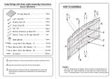
23 7/8"
24"
N405
6318
6319
6317
6316
N3
6319
6318
6317
6316
H216
H216
N3
N405
PRE-DRILLED
HOLES UP
*NOTE: 4x4 Monkey Bar can only be mounted on the Carnival Clubhouse and MUST NOT have
a Penthouse mounted on it.
1. Place Left and Right Monkey Bar Arms
(6316) (6317)
and Left and Right Monkey Bar Support Legs
(6318) (6319)
on a flat surface directly across from each other with pre-drilled hole facing up (as
(shown).
2. Insert Pipes
(N3)
in to pipe holes into both Monkey Bar Arms
(6316) (6317)
to connect the two Monkey
Bar Arms
(6316) (6317)
together.
*NOTE: Monkey Bar assembly must measure 23 7/8" wide when properly assembled.
3. Ensure width of Monkey Bar assembly is
23 7/8"
wide (as shown) and insert #8 Hardware
(H216)
through pre-drilled holes in Monkey Bar Arms
(6316) (6317)
into Pipes
(N3)
, to secure Pipes in pipe
holes.
4. Insert Pipes
(N405)
in to pipe holes into both Monkey Bar Support Legs
(6318) (6319)
to connect the
two Monkey Bar Support Legs
(6318) (6319)
together.
*NOTE: Inside of Monkey Bar Support assembly must measure 24" wide when properly
assembled.
5. Ensure width of Monkey Bar Support assembly is
24"
wide (as shown) and insert #8 Hardware
(H216)
through pre-drilled holes in Monkey Bar Support Legs
(6318) (6319)
into Pipes
(N405)
, to secure
Pipes in pipe holes.
87
Step 48
4x4 Monkey Bar
Assembly

*NOTE: A Helper will be needed to complete this Step.
*NOTE: Rail Uprights (9022) should not have been installed in the opening that the Monkey
Bar is being installed in. If Rail Uprights were installed, remove and reinstall after
Monkey Bar has been installed.
1. In the opening the Monkey Bar is being installed in, measure down from bottom of 6 Hole Facia
(4132)
1 11/16”
and drill a hole in each Corner Upright
(6302)
and Center Post
(6138) (6313)
, using a
7/16”
drill bit
(as shown in Inset A).
*NOTE: The 7/16” diameter holes must be drilled in the centers of the Corner Upright and
Center Post.
2. On the ground, position Monkey Bar inside of Monkey Bar Support, lining up the bottom hole in
Support with the back counter bored holes in Monkey Bar.
*NOTE: Orient the Monkey Bar Support so that the previously installed Hardware screwed into
the Pipes is facing toward the set. Orient the Monkey Bar so that the previously
installed Hardware screwed into the Pipes is facing down.
3. Attach Monkey Bar Support to Monkey Bar using 3/4” Hardware
(H5)
and 1/2” Hardware
(H4) (H12)
(H18) (H71)
. Do not fully tighten Hardware at this time.
4. Lift up on Monkey Bar and position Monkey Bar Brackets
(7024) (7025)
against Monkey Bar and
Support so that all faces of Monkey Bar, Support and Brackets are flush. Attach Monkey Bar
Brackets to Monkey Bar and Monkey Bar Support using 3/8” Hardware
(H3) (H116)
.
*NOTE: There should be no gaps in all adjoining faces of Monkey Bar Brackets, Monkey Bar
& Monkey Bar Support when properly installed.
5. Lift Monkey Bar assembly up into opening and align holes in Monkey Bar with previously drilled holes
in Corner Upright
(6302)
and Center Post
(6138) (6313)
.
6. Attach Monkey Bar to Corner Upright
(6302)
and Center Post
(6138) (6313)
using 1/2" Hardware
(H4)
and 3/8" Hardware
(H3) (H11) (H17) (H28) (H56)
.
7. Check that Monkey Bar is level and fully tighten Hardware from #3. Attach 1/2” Hardware
(H29)
to
the end of 1/2” Hardware
(H71)
from #3.
8. Position Safety Handles
(N391)
on Support, in approximate location shown, and attach Safety Handles
(N391)
to Support using 5/16" Hardware
(H104)
.
Continued on next page:
88
Step 49
4x4 Monkey Bar
Installation

A
H56
H4
H3
H11
H17
H28
6317
6316
6319
6318
N391
N391
H104
H104
H71
H5
H3
H116
7024
7025
H29
H18
H12
H4
H5
H71
H3
H116
H4
H56
6302
6138 6313
H3
H116
USE BOTTOM
HOLE IN
SUPPORT
B
1 11/16" 1 11/16"
7/16" DIAMETER
HOLE
4132
6138
6302
Continued from previous page:
6313
89
Step 49
4x4 Monkey Bar
Installation

A
H3
H119
6342
6302
6138
6313
6342
B
1 7/8" 1 7/8"
9222
H152
6342
6342
9223
4132
1. Position Monkey Bar Support Blocks
(6342)
against Corner Upright
(6302)
and Center Post
(6138)
(6313)
, pushed up tight to underside of Monkey Bar.
2. Attach Monkey Bar Support Blocks
(6342)
using 3/8" Hardware
(H3) (H119)
.
3. On inside of set, evenly space three Rail Uprights
(9222)
across Corner Facia
(9223)
and 6 Hole
Facia
(4132)
, in between Monkey Bar Support Blocks
(6342)
. Attach Rail Uprights using #8
Hardware
(H152)
.
*NOTE: Gaps between Rail Uprights and Support Blocks should measure approximately
1 7/8" when properly installed.
90
Step 50
Monkey Bar Support Block
& Rail Upright Installation
/