
2:1(56
0$18$/
+RZ WR PDLQWDLQ DQG RSHUDWH \RXU
(FR:DWHU ELUP ILOWHU ZLWK DLU LQMHFWHG DVVHPEO\
02'(/6
(7) $,,)
(7) $,,)

Unpacking, Table of Contents
ECOWATER
SYSTE MS
2
UNPACKING
EcoWater Air Injected Iron Filters are shipped from
the factory in four master cartons consisting of ...
...Mineral tank and adaptor assembly
...Controller assembly (includes this manual)
...Birm packed `
...Quartz packed
Thoroughly check the filter for possible shipping
damage and parts loss. Also inspect and note any
damage to the shipping cartons. Notify the trans-
portation company if damage is present. EcoWater
is not responsible for in-transit damages.
Removeanddiscard(RECYCLE)allpackingmateri-
als. Filter assembly instructionsare on pages5 & 6.
TABLE OF CONTENTS
PAGE
Unpacking 2
Warranty-Safety Guides 3
Specifications - Dimensions 4
Filter Assembly 6
Typical Installation Drawing 7
Where To Install The Filter 8
Installation Steps 9 -11
Plumb In and Out Pipes 9
Connect Valve Drain Hose 10
Connect Air Pump 11
Electrical Connections 11
Pressurizing System - Checking Work
For Leaks
11
Program Filter Timer 12- 13
Timer Features 13- 14
Service Information 18- 19
Repair Parts 20- 23
` Note: The birm will initially retain large amounts of air. If it is backwashed before the air is re-
moved, the valve may get plugged with birm particles, or particles may get flushed to the drain.
To remove the air, soak the birm in water for 24 hours prior to loading into the tank, or load the dry birm
into the tank, but do not allow the filter to regenerate until the birm has been wetted for at least 24 hours.

Warranty, Safety Guides
ECOWATER
SYSTE MS
3
EcoWater Systems, Inc.
Advantage Warranty
Series ETF AIIF Water System
Congratulations! You have just purchased the highest quality water conditioning
productonthemarket. Toregister yourwarranty, completetheenclosedWarranty
Registration Card and mail it within 30 days of purchase.
To whom is this warranty extended?
EcoWater Systems, Inc. warrants its products to the original owner and
guarantees that the products will be free from defects in materials and
workmanship from the original date of installation.
How does my warranty work?
If, during the respective warranty period, a part proves, after inspection by
EcoWater, to be defective, EcoWater will, atits sole option repair or replace that
part at no charge, other than normal shipping and installation charges.
What is covered by the warranty?
EcoWater systems, Inc. guarantees that,
for the LIFETIME of the original owner, theMINERALTANK willnot rust,corrode,
leak, burst, or in any other manner fail to perform its proper function and that,
fora periodof FIVE(5)YEARS afterinstallation, theVALVEBODY will be freeof
defectsinmaterials andworkmanshipandwillperformits properfunctionandthat,
for a period of THREE (3) YEARS after installation, the ELECTRONIC
FACEPLATEwill befreeofdefectsinmaterialsandworkmanshipandwillperform
its normal functions and that,
for a period of ONE (1) YEAR after installation, ALL OTHER PARTS will befree
of defects in materials and workmanship and will performtheir normal functions.
How do I obtain local service?
Should you need service, your local, independent EcoWater Dealer is only a
phone call away.
PHONE:
If I need a part replaced after the factory warranty expires, is that part
warranted?
Yes, EcoWater Systems, Inc. warrants FACTORY REPAIRS as well as all
REPLACEMENT PARTS for a period of 90 DAYS.
Are any additional warranties available?
We are pleased to say, YES! EcoWater Systems, Inc. offers an EXTENDED,
PARTS ONLY WARRANTY fortheELECTRONICS portion of your product. This
warranty is called the “Perfect Ten” and extends the three year warranty on the
electronicFACEPLATE,WIRINGHARNESS,DRIVEMOTOR,TRANSFORMER,
POWER CORD, SENSOR HOUSING, and MICRO SWITCHES to atotal ofTEN
YEARSfrom thedateof originalinstallation. Should yourlocal dealernotofferthis
warranty, you may contact the factory for additional information.*
General Provisions
The above warranties are effective provided the water conditioner is operated at
water pressures not exceeding 125psi, andatwatertemperatures notexceeding
120 F;providedfurther thatthe waterconditioner isnot subject to abuse,misuse,
alteration, neglect, freezing, accident ornegligence; and provided further thatthe
waterconditioneris notdamaged asthe result ofany unusual forceof naturesuch
as, butnot limited to,flood,hurricane, tornadoorearthquake. EcoWaterSystems,
Inc., is excused iffailure toperform its warranty obligations is theresult ofstrikes,
government regulation, materials shortages, or other circumstances beyond its
control.
Toobtain warrantyservice, notice mustbe given, within thirty(30) days of thedis-
covery of the defect, to your local EcoWater Systems dealer.
*THERE ARE NO WARRANTIES ON THE WATER CONDITIONER BEYOND
THOSE SPECIFICALLY DESCRIBED ABOVE. ALL IMPLIED WARRANTIES,
INCLUDING ANY IMPLIED WARRANTY OF MERCHANTABILITY OR OF
FITNESSFORAPARTICULARPURPOSE,AREDISCLAIMEDTOTHEEXTENT
THEY MIGHT EXTEND BEYOND THE ABOVE PERIODS. THE SOLE
OBLIGATIONOF ECOWATERSYSTEMS, INC. UNDER THESE WARRANTIES
IS TO REPLACE OR REPAIR THE COMPONENT OR PART WHICH PROVES
TOBE DEFECTIVEWITHIN THESPECIFIEDTIMEPERIOD,ANDECOWATER
IS NOT LIABLE FOR CONSEQUENTIAL OR INCIDENTAL DAMAGES. NO
ECOWATER DEALER, AGENT, REPRESENTATIVE, OR OTHER PERSON IS
AUTHORIZED TO EXTEND OR EXPAND THE WARRANTIES EXPRESSLY
DESCRIBED ABOVE.
Some states do not allow limitations on how long an implied warranty lasts or
exclusions orlimitations ofincidental orconsequential damage,so thelimitations
and exclusions in this warranty may not apply to you. This warranty gives you
specific legalrights, andyou may have otherrights which vary from state tostate.
This warranty applies to consumer-owned installations only.
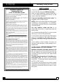
SAFETY GUIDES
Follow the installation instructions carefully. Failure
to install the filter properly voids the warranty.
Beforeyou begininstallation,read thisentiremanu-
al. Then, obtain all the materials and tools you will
need to make the installation.
Check local plumbing and electrical codes. The
installation must conform to them.
NOTE: Codesin the stateof Massachusettsrequire
installation by a licensed plumber. For installation,
useplumbingcode248-CMRoftheCommonwealth
of Massachusetts.
Use only lead-free solder and flux for all
sweat-solder connections, as required by state and
federal codes.
Usecarewhenhandlingthefilter.Donotturnupside
down, drop, or set on sharp protrusions.
Do not locate the filter where freezing temperatures
occur. Do not attempt to filter water over 120F.
Freezing, or hot water damage voids the warran-
ty.
Avoid installing in direct sunlight. Excessive sun
heat may cause distortion or other damage to non-
metallic parts.
The filter requires a minimum water flow of 7 gal-
lons per minute at the inlet for EDFNZDVK.
Maximum allowable inlet water pressure is 60
psi. Useapressurereducing valveifnecessary.Be
sure the addition of a pressure reducing valve will
not reduce the flow to less than the 7 gpm needed
for backwash.
This filter controller works on 24 volt-60 hzelec-
trical power only. Be sure to use the included
transformer. Theairpumpmustbeseparatelywired
to 110V or 220V service.
This system is not intended to be used for treating
waterthat ismicrobiologically unsafeor of unknown
quality without adequate disinfection before orafter
the system.

Specifiecations / Dimensions
ECOWATER
SYSTE MS
4
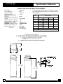
%,50 ),/7(5 :,7+ $,5 ,1-(&7,21 $66(0%/<
Filter Type 2[LGL]LQJ..................
Type of Mineral
%LUP.............
Amount of Mineral
FX IW...........
Amount of Gravel
OEV...........
Maximum Water Supply
Pressure
SVL...................
Recommended Type Water
Supply
:HOO 6\VWHP.....................
Maximum Water Temperature
E ).
Minimum Water Supply pH
...
Maximum Service Flow
JDO SHU PLQ......
Minimum Backwash Flow
➀ JDO SHU PLQ..
Minimum In-Out Pipe Size LQ....
Electrical: Filter Timer
9+]........
Air Pump
9+]..........
RU 9+]
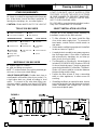
Some feed water with high iron concentrations, or low pH
may require limited service flows or a neutralizer filter be-
fore the system.
IRON
CONC.
MAXIMUM SERVICE FLOW RATE OF
IRON FILTER
20 PPM 4 4 4 4
15 PPM 4 4 4 5
10 PPM 4 4 4 6
5 PPM 4 4 5 7
2 PPM 4 4 6 8
6.5 7.0 7.5 8.0
pH
Neutralizer needed
Contaminant Removal Limitations:
up to 10 ppm iron* and 3ppm hydrogen sulfide at pH of 7.0 and higher
up to 20 ppm iron* and 2ppm hydrogen sulfide at pH of 8.0 and higher
up to 2 ppm manganese at pH of 8.5 and higher
* , bacterial and organically bound iron
➀ A minimum flow of 7 gpm is required for filter backwash.
14”
14”
71 - 3/8”
64 - 1/2”

Assembly Instructions
ECOWATER
SYSTE MS
5
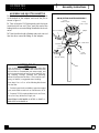
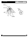
ASSEMBLE AIR INJECTOR ADAPTOR
1. Putthetop end of thefloat into the matching port
in the bottom of the adaptor and insert the pin as
shown in figure 1.
2. Take a length of 1/4” tubing and push the insert
(restrictor) into one end. Then, push this end of the
tubingintothe connectorfittinginstalledinthecheck
valve.
3. Taketheotherlengthoftubingandpush oneend
into the other connector fitting on the adaptor.
SANITIZING THE FIL-
TER
Care is taken at the factory to keep your water filter
clean and sanitary. Materials used to make the filter
will not infect or contaminate your water supply, and
will not cause bacteria to form or grow; however, dur-
ing shipping, storage, installing and operating,
bacteriacould get intothe filter. For this reason, sani-
tizing, as follows, is suggested when installing.
Pour about 1 oz. or 2 oz. of the followingdisinfectant
into the filter.
1. Calciumhypochlorite,availableingranularortablet
form, under trade names such as Perchloron orHTH.
2. Common5.25% householdbleachsuch asClorox,
Linco, Bo Peep, White Sail, Eagle, etc.
6$1,7,=,1* &217,18(' ,1 67(3 3$*(
$1' 67(3 21 3$*(
FIGURE 1
O-ring
2-7/8” x3-1/4”
O-ring
2-3/4” x3”
Adaptor
Float
Pin
O-ring
13/16” x1-1/16”
Insert
(restrictor)
Check Valve
1/4” x72” Tubing
1/4” x72” Tubing
AIR INJECTOR ADAPTOR ASSEMBLY
Connector

Assembly Instructions
ECOWATER
SYSTE MS
6
FILL THE MINERAL TANK
1. Remove the shipping cap from the mineral tank.
2. Fillthetankwiththe gravelandbirm,inthatorder.
Be sure the bottom distributor is centered in the
tank. Donotgetgravelandbirminside thedistri-
butor.
Note: The birm will initially retain large amounts of
air. If itisbackwashedbeforetheairisremoved,the
valve may get plugged with birm particles, or par-
ticles may get flushed to the drain.
Toremovetheair,soakthebirminwaterfor24hours
priortoloadingintothetank,orloadthedrybirminto
thetank,butdo notallowthefilterto regenerateuntil
the birm has been wetted for at least 24 hours.
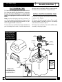
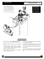
INSTALL ADAPTOR ON MINERAL TANK
1. Be sure o-ring seals are lubricated and installed
in place on the adaptor.
2. Be sure the tank opening is clean. Then, install
the tank adaptor as shown in Figure 2. Use clamps
and retainers to fasten in place.
3. Removethecontrollercoversandinstallthevalve
assembly, clamping in place.
Cover
Clamp
Retainer (4)
Clamp
Section (4)
Valve
Assembly
Adaptor
Assembly
Air Filter
POWER CORD,
to outlet wired in
parallel with well pump,
SEE WIRING
SCHEMATICS, PAGE 11.
TO DRAIN
(excess air)
Check Valve
Remove ship-
ping cap. It is
not used.
Iron Filter
Tank
Connector
FIGURE 2
Controller
Assembly
WARNING: FILTER
TANK CONTAINS AIR.
TO RELIEVE PRES-
SURE, PUT BYPASS
VALVE IN BYPASS AND
ADVANCE FILTER
VALVE TO BACKWASH
BEFORE DISASSEMBLY.

Planning Installation
ECOWATER
SYSTE MS
7
120 Volt
outlet
FILTERED
WATER
UNFILTERED
WATER
TO FILTER
INLET
FROM
FILTER
OUTLET
CROSS - OVER
Use if water supply flows from the left.
Include single or 3 - valve bypass.
transformer
FILTERED WATER
WATER IN
TO DRAIN
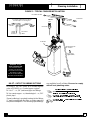
FIGURE 3 - TYPICAL FINI
S
HED INSTALLATION
WARNING: FILTER
TANK CONTAINS AIR.
TO RELIEVE PRES-
SURE, PUT BYPASS
VALVE IN BYPASS AND
ADVANCE FILTER
VALVE TO BACKWASH
BEFORE DISASSEMBLY.
DRAIN HOSE, 5/8”
I.D. minimum
to floor drain
(5gal./min.)
floor drain
1-1/2”
airgap
INLET - OUTLET PLUMBING OPTIONS
1. ALWAYS INSTALL either an EcoWater bypass
valve, #7214383, or a 3 valve bypass system.
2. Use 1”... or, 3/4” (minimum) pipe and fittings.
3. Usesweat copper...or,threadedpipe*...or,PVC
plastic pipe.*
*Sweat soldering is required to adapt to the fittings
(1” male) supplied with the filter, or obtain approved
compressionadaptors.Thefollowing specialfittings
are available from EcoWater. Be sure to comply
with all local plumbing codes.

Planning Installation
ECOWATER
SYSTE MS
8
OTHER REQUIREMENTS
4. Adrainis neededfor regenerationdischargewa-
ter. A floor drain, close to the filter is preferred. A
laundry tub, standpipe, etc., are other options.
CAUTION: DRAIN WATER EXITS THE HOSE AT
A FAST FLOW RATE, AND AT WATER SYSTEM
PRESSURE. BE SURE THE HOSE IS FASTENED
IN SOME MANNER TO PREVENT “WHIPPING”,
AND SPLASHING TO PREVENT WATER DAM-
AGE TO SURROUNDING AREA.
5. A120v-60Hz,groundedelectricaloutlet(continu-
ously “live” is need within 10’ of the filter.
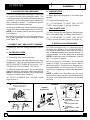
TOOLS YOU MAY NEED
common screwdriver pliers
cross-point screwdriver tape measure
SOLDERED COPPER THREADED CPVC PLASTIC
tubing cutter hacksaw or
pipe cutter
hacksaw
propane torch threading tool adjustable
wrench
LEAD-FREE
solder and flux
pipe joint com-
pound*
solvent cement*
emery cloth,
sandpaper or steel
wool
primer
MATERIALS YOU MAY NEED
1 bypass valve, or 3 valves
1 pipe and fittings as required
1 5/8”I.D.minimumdrainhose,eitherstandardgar-
den hose, or hose onto a barb fitting*
*VALVE DRAIN OPTIONS: Flexible drain hose is
not allowed in all localities (check your codes). For
a rigid valve drain run, plumb according to local
codes. To connect to the valve drain fitting, pur-
chase an adaptor, garden hose thread x 5/8” (mini-
mum)tube. Use ahacksaw tocut barbsfromthe fit-
ting.
SELECT INSTALLATION LOCATION
Consider all of the following when selecting an
installation location for the filter selected.
: To filter all water in the home, install the filter
close to the water supply inlet. To conserve fil-
tered water, outside faucets should remain on
raw water.
: Ifotherwaterconditioningequipmentisinstalled,
locate as shown in Figure 4.
: Anearbydrainisneededtocarryawayregenera-
tion discharge water. A floor drain is preferred,
with a laundry tub, standpipe, etc., as other op-
tions (check your local codes).
: Thefilterworkson24voltsonly. A transformeris
included(FORINDOORUSE)toreduce120V-60
Hzhouse electricalpower.Provide an approved,
groundedoutletwithin10’ofthefilter.Thefilterin-
cludes a10’powercableforconnectionbetween
the transformer and the timer.
: Position the filter at least 6” from surrounding
walls, or other appliances, to allow access for
servicing.
: Ifinstallingthefilterinanoutsidelocation,besure
toprovideprotectionfromthe elements,contami-
nation, vandalism, and sunlight heat. The sun’s
heat can melt plastic parts.
FIGURE 4

Installation
ECOWATER
SYSTE MS
9
1. INSTALL INLET AND OUTLET FITTINGS
Note: All fittings are in the small parts bag.
a. Insert the turbine support, into the valve outlet
port, up to the shoulder.
NOTE: If installing the EcoWater bypass
valve,
see separate instructions included with it.
b. Slide a lubricated o-ring onto one of the copper
tubes. Carefullyinsertthecoppertubeintotheoutlet
port (Figure 5) and secure in place witha plastic“C”
clip.
Note: For lubrication, use silicone grease approved
for use on potable water supplies.
c. Repeat step b on the inlet side.
2. TURN OFF WATER SUPPLY
a. Close the main water supply valve, near well
pump or water meter.
b. Shut off the electricity or fuel supply to the water
heater.
c. Open high and lowfaucets todrainallwaterfrom
hose pipes.
3. INSTALLING 3-VALVE BYPASS
Ifinstallinga3-valvebypasssystem,plumbasneed-
ed. Ifinstallingsweatcopper,besuretoUSELEAD-
FREE SOLDER as required by Federal and State
codes. Use pipe joint compound on outside pipe
threads.
4. MOVE FILTER INTO PLACE
Move the filter into the installation position, setting
on a solid, smooth and level surface. If needed,
place the filter on a section of 3/4” plywood. Then
shimundertheplywoodtolevelthefilter,FIGURE6.
CAUTION: DO NOT PLACE SHIMS DIRECTLY
UNDERTHESHROUD. The weightofthe tankmay
cause the shroud to fracture at the shim.
5. ASSEMBLE INLET AND OUTLET PLUMBING
Measure,cutand looselyassemblepipe andfittings
from the main water pipe (or from bypass valves
installedinstep3),tothefilterinletandoutletcopper
tubes.
BE SURE UNFILTERED WATER
SUPPLY PIPE
GOESTOTHEFILTERINLET
SIDE. Trace thewa-
ter flow direction to be sure.
VALVE
INLET
o-ring seal (2)
1” copper tube (2)
clip (2)
turbine support
FIGURE 5 FIGURE 6
shroud
3/4” plywood
shim

Installation
ECOWATER
SYSTE MS
10
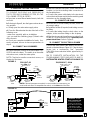
6. COLD WATER PIPE GROUNDING
Thehousecoldwaterpipe(metalonly)is oftenused
as a ground for the house electrical system. The
3-valvebypasstype,ifinstalled,willmaintainground
continuity. If you usethe plasticbypassvalve at the
filter, continuity is broken. To restore the ground,
install one of the following grounds.
a. Usetheincluded hose clamps andwire to jumper
acrosstheinletandoutletcoppertubesFIGURE7a.
NOTE: Hose clamps must be placed on pipes be-
fore soldering.
b. Install a #4 copper wire across the removed sec-
tion of main water pipe, securely clamping on both
ends (figure 7b).
7. CONNECT INLET AND OUTLET PLUMBING
Complete the inlet and outlet plumbing as applica-
ble.
a. SOLDERED
COPPER
(1) Thoroughly clean and flux all joints.
(2) Removetheinletandoutlettubesfromthevalve
(pullplastic“C”clips),ando-ringsfromthetubes.DO
NOTSOLDERWITHTUBESIN THEVALVE. SOL-
DERING HEAT WILL DAMAGE THE VALVE.
(3) Makeallsolderconnections. Be sureto keepfit-
tings fully together, and pipes square and straight.
NOTE: Ifusingground(step6a),hose clampsmust
be placed on pipes before soldering.
(4) AFTER PLUMBING HAS COOLED, repeat
steps 1b and 1c.
b. THREADED
PIPE
(1) Apply pipe joint compound to all outside pipe
threads.
(2) Tighten all threaded joints.
(3) If SOLDERING TO INLET AND OUTLET
TUBES, observe steps (1) through (4) above.
c. CPVC PLASTIC
PIPE
(1)Clean,primeandcementalljoints(followinstruc-
tions of the plastic pipe and fittings manufacturer).
(2) IF SOLDERING TO INLET AND OUTLET
TUBES, observe preceding steps (1) through (4).
8. INSTALL VALVE DRAIN HOSE
a. Connect a length of 5/8” I.D. (minimum) hose to
the valve drain elbow on the controller FIGURE 3.
The elbow accepts either a hose onto the barb fit-
ting, or standard garden hose onto the threads. To
use the threads, cut off the barbs with a hacksaw.
NOTE: Flexible drain hoseisnotallowedinalllocali-
ties. See option on page 8.
b. Run the hose to a floor drain, and as typically
shown in FIGURE 2, tie orwire the end to a brick or
otherheavyobject. Thiswillprevent “whipping”dur-
ing regenerations. Be sure to provide a 1-1/2” mini-
mumairgap, toprevent possiblesewer waterback-
up.
NOTE: In addition to a floor drain, you can use a
laundry tub or stand pipe as a good drain point for
this hose. Avoid long drain hose runs, or elevating
the hose.
ground wire
clamp (2)
FIGURE 7
FIGURE 8
B
A
3 - Valve Bypass
OUTLET
VALVE
INLET
VALVE
BYPASS
VALVE
to conditioner
from conditioner
EcoWater
Bypass Valve
for SERVICE:
-Openthe inlet and outlet
valves.
-Closethe bypass valve.
for BYPASS:
-Closethe inlet and outlet
valves.
-Openthe bypass valve.
Install hose clamps before
soldering copper tubes
copper
tubes
hose clamp,
ground (2)
ground wire

Installation
ECOWATER
SYSTE MS
11
9. PRESSURE TESTING FOR LEAKS
TO PREVENT EXCESSIVE AIR PRESSURE IN
THE FILTER AND PLUMBING SYSTEM, DO THE
FOLLOWING STEPS IN ORDER
a. Open two or more filtered waterfaucets, both hot
and cold.
b.Referringtofigure8,turnthebypassvalvestoser-
vice position.
c. Slowly open the main water supply valve.
d. Close the filtered water faucets after both of the
following occur.
- water runs smoothly, with no air bubbles
- you can smell the sanitizing (page 5) bleach odor
at the faucets
e. Check your complete installation for leaks. If re-
work is required, be sure to observe precautions in
step 6.
10. CONNECT ALL LEADWIRES
a.Connectthewireharnessto thevalveswitchFIG-
URE 10 andto the timer. The switch is on the outlet
side valve cover, under the motor plate.
NOTE:Checktobesuretheconnectorissecure,on
the back of the timer.
b. Attachthe femaleconnectors, on the valve motor
leadwire, to the the matching male connectors on
the faceplate timer.
c. Connect the power cable leads to the two termi-
nalsonthetransformerandtothethematchingmale
connectors on the faceplate timer.
11. CONNECT AIR PUMP
a. On the flooror a shelf nearby the filter, fasten the
air pump in place.
b. Installthe airfilter(ifrequired)and tubingconnec-
tor fitting.
c. Connect the tubing from the check valve, on the
adaptor, to the connector fitting on the air pump.
d.Wirethe airpump tothe wellpumptocycle offand
on withit. Thisshould be done by a qualified, com-
petent electrician. RefertoFigure9.
12. CONNECT TO ELECTRICAL POWER
Connect the timer power cable leads to the two ter-
minalsonthetransformerFigure10. Plug thetrans-
former into a continuously “live”, grounded,
120V-60Hz house electrical outlet, approved by lo-
cal codes.
13. TO COMPLETE INSTALLATION, DO THE
PROGRAMMING STEPS ON PAGES 12 AND 13.
NOTE WATER HEATER START-UP ON PAGE 13.
WELL
PUMP
PUMP
PRESSURE
SWITCH
110/120 V
AIR PUMP
NEMA 5-15R TYPE
RECEPTACLE
120 V
POWER
SOURCE
230 V
POWER
SOURCE
L2
P. CORD
L1
NEUTRAL
NEMA 6-15R TYPE
RECEPTACLE
WELL
PUMP
PUMP
PRESSURE
SWITCH
P. CORD
L1
L1
L2
L2
GND
L1
NEUTRAL
GND
220 V
AIR PUMP
NOTE: If thewell pumppressure switchis not accessible forsome reason,you
must install and wire to a compatible flow switch, on the inlet side of the filter.
Position Switch
Motor
120 V
Power
Source
24V
Transformer
Back of Solid State
Timer PWA
WH.
GRN.
HEADER 1 HEADER 2
shunts on both
headers
WARNING: FILTER
TANK CONTAINS AIR.
TO RELIEVE PRES-
SURE, PUT BYPASS
VALVE IN BYPASS AND
ADVANCE FILTER
VALVE TO BACKWASH
BEFORE DISASSEMBLY.
FIGURE 9
220 VOLT, 60
Hz
110/120 VOLT, 60 Hz
FIGURE 10

Programming Face Plate Timer
ECOWATER
SYSTE MS
12
FIGURE 11
displaydisplaydisplay
CURRENT TIME
AND DAY keypad
RECHARGE TIME
keypad
RECHARGE
DAYS
keypad
SET keypad
VACATION / RECHARGE NOW
keypad
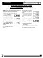
1.Whenthetransformerispluggedintotheelectrical
outlet,12:00 AM,SUndaybegins toflashin thetime
display. Set the time of day and present day of
week as follows:
A.SetTimeofDay
1. Press the CURRENT TIME AND DAY keypad
once. The hour display continues to flash.
2.PresstheSETkeypaduntilthepresenthourofthe
day shows in the display. Be sure AM for morning
hours, or PM for afternoon and evening hours
shows.
Note: Press SET and quickly release to move the
hour display ahead one hour at time to the correct
hour. Or, hold the SET keypad to move the display
ahead two hours each second, to the correct hour.
3. PressCURRENT TIMEANDDAYkeypadonceto
steady the hour display,and minutesbegin to flash.
Press SET until the correct minutes show in the dis-
play.
4. Press CURRENT TIME AND DAY keypad again
tosteadytheminutedisplay(daywillbeginflashing).
B. Set Present Day of Week
1. Press the SET keypad to set the present day of
the week in the display.
Note: Press SET and quickly release to move the
daydisplay oneday at atime, hold the SETkeypad
to move the display ahead two days each second.
2. Press the CURRENT TIME AND DAY keypad
again to steady the entire display.
C. Set Days and Time of Backwash
Note: The timer is factory set (default time) for
Monday, Wednesday, and Saturday backwashes,
beginning at 12:00 AM. If you have an Eco Water
conditioner or another filter installed, the backwash
timer and/or days should be offset to assure ade-
quatewaterflowandpressure. Forexample,setthe
filter to start backwash at 12:00 AM, or 4:00 AM, if
the conditioner is set to begin recharge at 2:00 AM.
1.PressRECHARGETIME keypadonce, todisplay
the factory set backwash days and starting time
(flashing). To change the backwash start time, do
step 2 following, otherwise proceed to step 3.
2.PresstheSETkeypaduntilthedesiredbackwash
starting time shows in the display.
Note: Press SET and quickly release to move the
displayaheadonehouratatime,holdthe SETkey-
pad to move the displayahead twohours each sec-
ond.
3. Press the RECHARGE DAYS keypad and
SUnday begins to flash.
...If you want backwashes on Sunday, press the
SET keypad to display ON.
NOTE: One backwash each week is usually suffi-
cient to keep the mineral bed clean and expanded.
If the water supplycontains iron, or highsediments,
additional backwashes may be needed.
...If you do not want Sunday backwashes, press
SET keypad to display OFF.

Programming Face Plate Timer
ECOWATER
SYSTE MS
13
4. Press the RECHARGE DAYS keypad again to
display a flashing MOnday and ON (factory set re-
charge). As you did in step 3, use the SET keypad
to change the display from ON to OFF, or fromOFF
to ON, as desired.
5. Press RECHARGE DAYS keypad to display a
flashing TUesday, WEdnesday, etc., each time us-
ing the SET keypad to display either ON or OFF as
needed.
2. Press and hold the VAC/RCHG keypad for three
seconds until RCHG begins to flash in the display,
starting a backwash. This backwash flushes“fines”
fromthenewmineral,andpurgesairandbleach,re-
maining fromthe sanitizingprocedure. The filterre-
turns to service in about 45 minutes.
3. RESTART THE WATER HEATER: Turn on the
electric or fuel supply to the water heater, and light
the pilot, if applies. Note: The water heater is filled
with unfiltered water and, as hot water is used, it re-
fills with filtered water. In a few days, hot water will
be fully filtered. To have fully filtered water immedi-
ately, wait until the recharge (step 2 above) is over.
Then, drain the water heater until water runs cold.
THE SOLID STATE TIMER IS NOW
PRO-
GRAMMED AND INSTALLATION IS
COMPLETE.
FEATURES / OPTIONS
RECHARGE NOW - For an immediate extra back-
washatanytime. Pressandholdin theVAC/RCHG
keypad for three seconds until RCHG flashes in the
display. The filter backwashes for 25 minutes, fol-
lowed by a 5 minute fast rinse cycle. Then the filter
returns to service.
VACATION -Thedayyouleave onvacation, oroth-
erlongabsence,press(DONOTHOLDIN)theVAC/
RCHG keypad. VAC begins to flash in the display.
The timer will keep time, but the filter will not back-
wash and waste water.
Note: Whilein the VACATION setting,the filterwill
go through a backwash if the RECHARGE NOW
feature is used (see above).
WHEN YOU RETURN, press the VAC/RCHG key-
pad again to return the filter to service, and the cor-
recttimeofdayinthedisplay. Rememberto tothis
or the filter will not backwash and you will soon
have unfiltered water.
DOUBLE BACKWASH - Although available on this
timer, a double backwash cycle is not normally
neededwithasediment,tasteandodor,orneutraliz-
ing filters. To set, if desired...
1. Press and hold SET until
18:88 showsin the display..
2. Press CURRENT TIME
AND DAY to display 3
dashes.
3. PressSETtodisplaydbl.
4. Press CURRENT TIME
AND DAY to display 18:88.
5. Press SET to return present time.
To cancel double backwash, repeat the above
steps. Displays for dbl and --- occur in reverse or-
der.
TIMER “POWER-OUTAGE MEMORY” - If electri-
cal power to the timer goes off, the “memory” built
into the timer circuitry keeps all settings for at least
twodays ormore. The displayis blankand thefilter
willnotbackwash. Whenelectricalpowercomeson,
one of two things will happen.
1. The present time of day will show, meaning the
timer memory has kept all settings.
1RWH ,I WKH ILOWHU ZDV LQ D EDFNZDVK ZKHQ SRZHU
ZDV ORVW LW ZLOO QRZ ILQLVK WKH F\FOH
2. Thedisplaywillshowa time,but itwill beflashing.
Thetimermemorydidnotkeepthetimesettingsand
they must be reset.
Theflashingdisplayis toremindyoutoresetthe
timer.
Notes:
When power comes on, the flashing display returns
to a time of 12:00 AM SUnday, then begins to keep
time again. If you do not reset all time settings, the
filter will backwash three days each week (default
time). However, backwash may be on the wrong
days and at the wrong time.
If the filterwas in a backwash when power went off,
the valve willreturntoserviceposition withoutfinish-
ing the cycle. If yourwater isunfiltered, use the RE-
CHARGE NOW feature to start another cycle.

Programming Face Plate Timer
ECOWATER
SYSTE MS
14
INFORMATION FOR QUALIFIED TECHNICIANS
ONLY
RECHARGE CYCLE TIME ADJUSTMENTS: Factory set default cycle times are:
BACKWASH...25 minutes, and FAST RINSE...5 minutes. Do the following to check for correct cycle times.
Note: Removing from electrical power (about two
days) resets times to factory set defaults.
DISPLAY MUST SHOW TIME AND DAY
1. Press and hold SET ...
entire display comes on.
2. Press RECHARGE TIME
... 2:00 should show in the
display. If not, press SET
until 2:00 does show.
3. Press RECHARGE TIME
... 3:25 shows, meaning #3
cycle (backwash) and 25
minutes.
a. If 3:25 does show, go to
step 4.
*b.Ifotherthan3:25(3:00to
3:30), press SET until 3:25
shows.
4. Press RECHARGE TIME
... 4:05 shows, meaning #4
cycle (fast rinse) and 5 min-
utes.
a. If 4:05 does show, go to
step 5.
b. If other than4:05 (4:00to
4:30), press SET until 4:05
shows.
5. PressRECHARGETIME
... 18:88 shows.
6. Press SET to return present time and day.
*Or, set other cycle length, if desired.

Filter Operation
ECOWATER
SYSTE MS
15
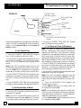
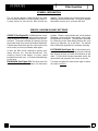
GENERAL
INFORMATION
The air injector adaptor installs between the filter
valve and mineral tank as shown below in figure 2.
A pump injects air into the iron filter through the
adaptor. The air oxidizes iron and it is mechanically
filteredbythefiltermineralbed.Theinjectoradaptor
float allows excess air to vent from the tank.
SERVICE, BACKWASH AND FAST RINSE
SERVICE (See Figure 12): Unfiltered water enters
the valve inletport. Internalvalve porting routes the
waterdown and out the top distributor, into the min-
eral tank. The water is filtered as it passes through
the mineral bed, then enters the bottom distributor.
Filtered water flows back into the valve and out the
valve outlet, to the house filtered water pipes.
In time, the filter needs cleaning to remove sedi-
ments, dirt, iron, etc., from the mineral bed. This
cleaning is done in two stages, or cycles, called
backwash and fast rinse. It is started automatically
by the timer.
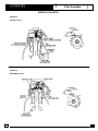
BACKWASH (See Figure 13
): The timer starts the
valve motor and moves the valve into backwash
position. Water is routed down and out the bottom
distributor, up through the mineral bed, and out the
top distributor to the drain. The fast flow(controlled
by a flow plug in the drain fitting) flushes dirt, sedi-
ments, iron deposits, etc. to the drain. The mineral
bed is lifted and expanded for maximum cleaning.
FAST RINSE (See Figure 14)
: Valve rotation posi-
tionsthe innerdiscssowaterflowentersthemineral
tank through the top, and exits at the bottom, to the
drain. The fast flow of water downward, packs the
mineral bed and prepares it for return to service.
The timer energizes the valve motor again to return
the valve to service
.

Filter Operation
ECOWATER
SYSTE MS
16
WATER FLOW PATHS
FIGURE 12
SERVICE CYCLE
FIGURE 13
BACKWASH CYCLE

Filter Operation
ECOWATER
SYSTE MS
17
FIGURE 14
FAST RINSE CYCLE

Service Information
ECOWATER
SYSTE MS
18
TO DRAIN
WARNING: FILTER
TANK CONTAINS AIR.
TO RELIEVE PRES-
SURE, PUT BYPASS
VALVE IN BYPASS AND
ADVANCE FILTER
VALVE TO BACKWASH
BEFORE DISASSEMBLY.
Adaptor Troubleshooting Guide
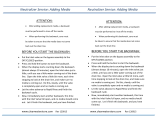
If excess air is in household plumbing, the
air vent is most likely plugged with debris.
Temporarily move the pump tube to the
drain fitting and energize the air pump.
After vent is cleared, change tubing back.
TROUBLESHOOTING
ALWAYS MAKE THESE INITIAL CHECKS FIRST
1. Does the time display show the correct time of
day?
...Ifdisplayisblank, checkpowersourceto thefilter.
...If time isflashing,powerwasoff forovertwodays.
The filter resumes normal operation but back-
washes occur at the wrong time.
2. Plumbing bypass valve(s) must be in SERVICE
position (see figure 7, page 9).
3.Theinletandoutletpipesmustconnecttothefilter
inlet and outlet respectively.
4. Is the transformer plugged into a “live” grounded
wall outlet, and the powercable fastened securely?
5. The valve drain hose must be free of kinks and
sharp bends.
If youdo notfind the problemafter making the initial
checks, do the MANUAL ADVANCE DIAGNOS-
TICS.

.
.
Service Information
ECOWATER
SYSTE MS
19
MANUAL ADVANCE DIAGNOSTIC
Use the following procedures to advance the filter
valve through the regeneration cycles to check op-
eration.
Remove the top cover to observe cam and switch
operation during valve rotation.
DISPLAY MUST SHOW TIME AND DAY
1. Press and hold set for 3
seconds until 18:88 displays.
2. Press RECHARGE DAY to
display the position switch
open or closed indicator.
The letter (P) and dash or
dashes indicate position
switch operation. The letter
shows if the switch is closed.
A dash shows when the
switch is open.
NOTE:7KH SRVLWLRQ VZLWFK LV FORVHG ZKHQ WKH SOXQJ
HU LV GHSUHVVHG RSHQ ZKHQ H[WHQGHG
CORRECT SWITCH
DISPLAYS
VALVE CYCLE STATUS
-- valve in service, backwash or
fast rinse position
-P valve rotating from one posi-
tion to another
NOTES:
While inmanual advance,the timedisplay willauto-
matically return to the present time, if a face plate
keypad is not pressed within four minutes.
Pressing VAC/RCHG while the motor isrunninghas
no effect.
3. To enter backwash, press and hold VAC/
RCHGfor three seconds to start the motor.
a. If the motordoes not run, check the motorand all
wiring connections.
Lookforafastflowofwaterfromthedrainhose(see
specs).
a.Anobstructedflowindicatesapluggedtopdistrib-
utor, backwash flow plug, or drain hose.*
*Note: Be sure household waterpressure (wellsys-
tem)ismaintainedataminimumof20psi. Adjustthe
pump switch upward, if needed.
4.PressVAC/RCHGtomovethe filterintofastrinse.
Again, lookforadrain flowrate aboutthe same and
in backwash.
5. To return the filter to service, press VAC/RCHG
once.
6. Upon returning to service, press RECHARGE
DAY to display 18:88.
7. Press SET to return to the present time.
OTHER SERVICE
UNFILTERED WATER BYPASS (unfiltered water
“bleeds” into filtered water supply.
1. Defective inlet disc, seal or wave washer (see
pages 22 and 23).
2.Missing ordefectiveo-ring(s)atresintanktovalve
connection (see pages 20 & 21).
AUTOMATIC ELECTRONIC DIAGNOSTICS
The face plate has a self diagnostic function for the
electrical systems (except input power). The face-
plate monitors the electronic components and cir-
cuits for correct operation. If a malfunction occurs,
an error code appears in the faceplate display.
POSSIBLE DEFECT
CODE MOST LIKELY
➤--------------------------------------➤ LEAST LIKELY
Err 01 Err 02
Err 03 Err 04
wiring harness or connection to position switch / switch / valve defect causing high torque
/ motor inoperative
Err 05 faceplate
PROCEDURE FOR REMOVING ERROR CODE FROM FACEPLATE: 1. Unplug transformer---- 2. Correct defect----3. Plug
intransformer----4.Waitfor6 minutes.The errorcodewillreturn ifthe defect was not corrected. Press and hold the
keypad
for 3 seconds as an alternate way to clear an error code.

Repair Parts
ECOWATER
SYSTE MS
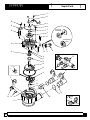
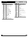
20
8
10
9
4
11
12
13
14
15
16
6
7
5
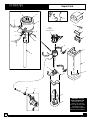
Valve
Assembly
(see page 22)
1
2
3
WARNING: FILTER
TANK CONTAINS AIR.
TO RELIEVE PRES-
SURE, PUT BYPASS
VALVE IN BYPASS AND
ADVANCE FILTER
VALVE TO BACKWASH
BEFORE DISASSEMBLY.
26
18
22
19
23
21
17
25
20
24
24
26
27
Page is loading ...
Page is loading ...
Page is loading ...
Page is loading ...
-
 1
1
-
 2
2
-
 3
3
-
 4
4
-
 5
5
-
 6
6
-
 7
7
-
 8
8
-
 9
9
-
 10
10
-
 11
11
-
 12
12
-
 13
13
-
 14
14
-
 15
15
-
 16
16
-
 17
17
-
 18
18
-
 19
19
-
 20
20
-
 21
21
-
 22
22
-
 23
23
-
 24
24


Ask a question and I''ll find the answer in the document
Finding information in a document is now easier with AI
Related papers
-
EcoWater ETF2100 PF Owner's manual
-
-
-
-
-
-
-
-
-
EcoWater ETF AIV-10 Owner's manual
Other documents
-
ISPRING UVT11A Operating instructions
-
Sears 625.348241 User manual
-
Kenmore 625348233 Owner's manual
-
North Star 7263146 Installation guide
-
-
Oatey 30041 Installation guide
-
 Protect Plus WFTST010 User manual
-
Hydrotech 89BM-150 Operating instructions
-
Hellenbrand Iron Curtain IC-10+ User manual
-
 Clack Corosex or FloMag pH Filter Media 10 Lb User guide

