FRONT
BACK
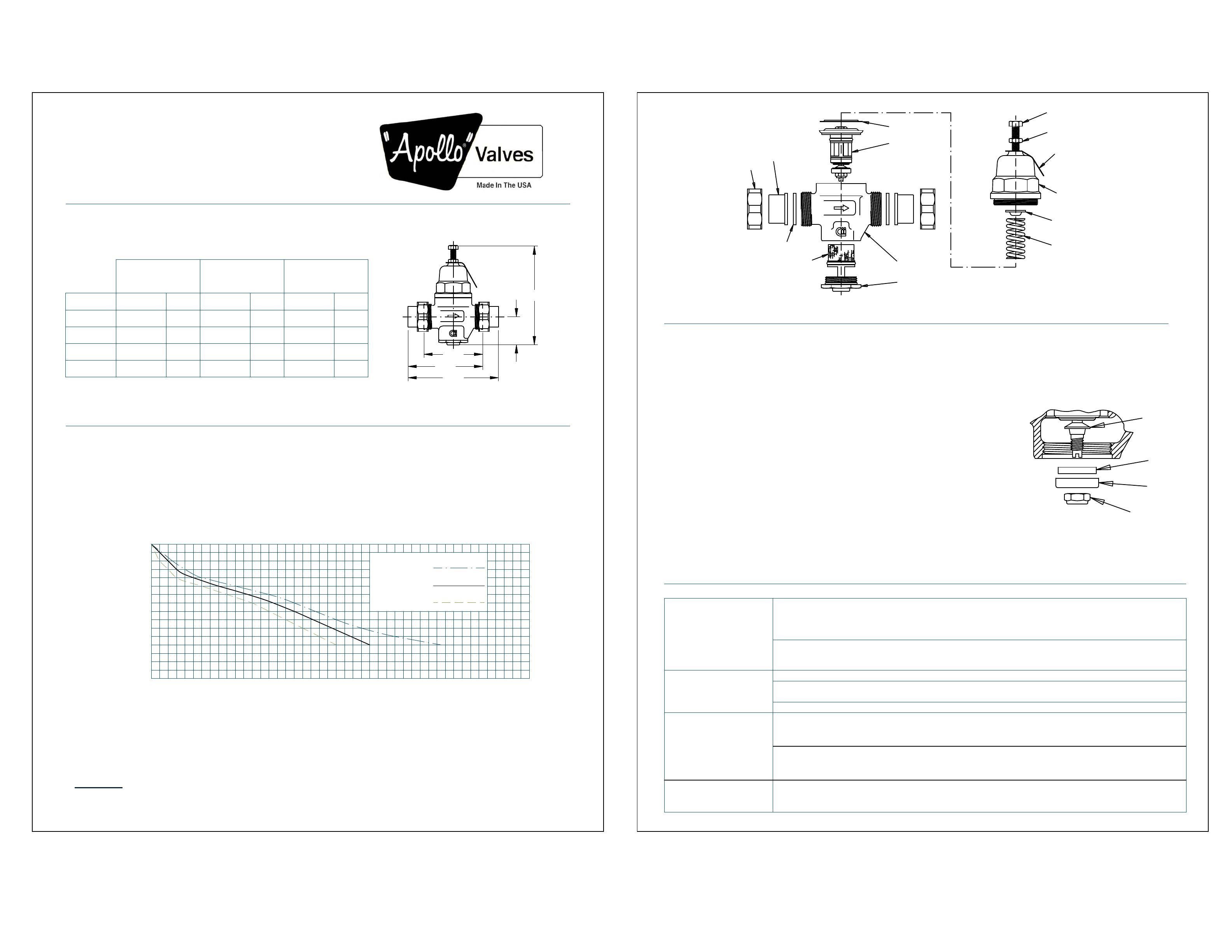
PRESSURE REDUCING VALVE
CONBRACO INDUSTRIES, INC., 1418 Pearl St., Pageland, S.C. 29728 Phone: (704)841-6000
(36C SERIES)
Installation
Size 1/2" & 3/4" 1/2" & 3/4" 1/2" & 3/4"1" 1" 1"
A
B
C
D
3 1/2"
N/A
N/AN/A
N/A N/A N/A
N/AN/AN/AN/A
N/A N/A
1 5/8" 1 1/2"
3 3/4"
4 13/32" 4 3/4"
1 1/2"1 5/8"
5 3/8"
1 5/8"
5 7/8"
1 1/2"
Non-union
(npt x npt)
Inlet-union Double-union
(npt, solder or
meter x npt)
(npt, solder or
solder x solder)
TABLE 1
Dimensions
(inches)
NOTE:
Operation
Example:
NOTE:
FIGURE 1
NUT
TAILPIECE
GASKET
STRAINER BODY
CLEAN-OUT PLUG
ASSEMBLY
FRICTION RING
(INNER LIP UP)
CARTRIDGE
ASSEMBLY
ADJUSTING
SCREW
LOCK NUT
NAMEPLATE
CAP
ASSEMBLY
SPRING DISC
SPRING
Maintenance
A major repair kit is also available (36C-004-01) to replace the cartridge assembly
and the two clean-out plug O-rings. Normally, the cartridge assembly does not require
servicing but can become damaged due to freeze-up or over pressurizing. In this case,
the cap assembly and the clean-out plug will have to be removed.
CAUTION: Always relieve the spring pressure by unscrewing the adjusting screw
before attempting to unscrew the cap assembly.
Unscrew the cap assembly by placing a wrench on the 1-3/4" hex and turn counter-
clockwise. With the cap off, use a finger from the bottom to push the cartridge assembly
out through the top. Reverse the previous procedure when re-assembling. Be certain that
the O-rings are lubricated with a non-toxic lubricant and free of foreign particles. Do not
over tighten the cap assembly. Turn the adjusting screw to re-establish the pressure setting. Use a gauge to check the pressure
in the downstream line. Flow a small amount of water and double-check the setting. Tighten the lock-nut.
FIG. 2
STEM
SEAT
DISC
SEAT
HOLDER
LOCK NUT
Trouble-Shooting
1. Gauge indicates outlet
set pressure rises above
the original setting.
A. If the rise is slow and not immediately noticed, the problem could be thermal expansion in the
downstream line. If this is the problem, the pressure should drop immediately after flow resumes.
If the pressure is not relieved and rises to equal the inlet pressure to the PRV, the by-pass feature
then will prevent any further increase by by-passing the pressure upstream.
2. Lack of flow. A. Lack of pressure at the supply. Fluctuations at the source may be temporary and correct itself.
C. Clogged strainer in the PRC. Remove clean-out plug and rinse strainer.
3. Excessive noise within
the pipeline at the PRV.
4. Leakage from cap.
PROBLEM POSSIBLE CAUSES
0
6
12
18
24
30
510152025303540
CHART 1
C
APACITIES
SET PRESSURE DIFFERENCE = 50 PSI @ STATIC, NO-FLOW
KEY
FLOWRATE (GPM)
PRESSURE FALL-OFF (PSI)
Although this chart shows curves at a 50 psi set differential, curves for other settings are similar. The curve
shifts sightly to the left for a smaller differential and to the right for a greater differential. The adjustment is as
follows: for a 25 psi set differential subtract 15% from the flow rate shown. For a 75 psi set differential add 15 % to
the flow rate shown.
I548300
MODEL PRC 1/2"-1"
* (the low range PRC comes set at 25 psi and is adjustable from 10-35 psi; the high range comes set at 100 psi and is adjustable from 75-125 psi)
PRC 1/2"
PRC 3/4"
PRC 1"
Prior to installing the PRC, all debris should be flushed from the line. Isolate
the section where the PRC is to be installed by closing the appropriate shut-off valves. Refer to Table 1 below for length
dimensions for the size and end configuration of the PRC you plan to install. The PRC is designed to be
installed in a piping system with the arrow on the valve pointing in the direction of flow.
The PRC is designed to reduce pressures up to 400 psi to a more functional level within its adjustment range.
The standard PRC is factory set at 50 psi outlet pressure and is adjustable from 25 to 75 psi.* To increase the
set pressure, loosen the locknut and turn the adjusting screw clockwise. To decrease the set pressure, turn the adjusting screw
counterclockwise. Re-tighten the locknut. Allow for some fall-off from set pressure during flow conditions. Refer to Chart 1
below to determine the amount of fall-off to expect at a certain rate of flow.
A PRC 3/4" has a inlet pressure of 100 psi and a set outlet pressure of 50 psi in the static, no-flow
condition. The flow demand through the valve is expected to be 19 gpm. The chart shows the pressure fall-off to be
about 18 psi. Thus the pressure will drop from 50 psi to approximately 32 psi at that flow rate.
The PRC is designed so that it can be serviced through the clean-out plug without removing the cap assembly
and disturbing the pressure setting. Routine servicing usually requires that the strainer be cleaned to remove debris that can
become caught on the strainer. Over time a clogged strainer can severely limit flow resulting in a high pressure loss across the
device. Less frequently, the rubber seat disc may need to be replaced as they sometimes become embedded with grit or other
foreign particles. Both the strainer and seat disc can be accessed from the clean-out plug (see figure 2). The plug uses a 1-1/2"
hex drive. A clean-out repair kit (36C-003-01) is available that includes the seat disc,
locknut, and two plug O-rings. Removing the lock nut requires a standard screwdriver
to hold the stem from rotating while turning the nut with a 7/16" wrench. Assemble in
reverse order. Tighten the lock nut firmly.
C
A
B
D
6"
Loose cap, damaged diaphragm, or loose center bolt o
n cartridge assembly. If tightening the cap
will not correct the leakage, then inspect the cartridge assembly. Check to see if the center bolt is
tight. If the diaphragm is damaged, replace the cartridge assembly.
WITH INTEGRAL BY-PASS FEATURE
If a solder union is to be used, sweat the union tailpiece and nut onto the pipe prior to installing the PRC
assembly, otherwise the heat could damage the assembly components.
B. A PRC that quickly rises above its set outlet pressure indicates some sort of seal leakage
within the valve. Remove the clean-out plug and inspect the plug O-rings and the seat disc for
cuts or debris. Clean or replace as necessary.
B. Several fixtures in the downstream line may be open creating a high demand. It may be
necessary to adjust the PRC to a higher setting if a higher flow demand is required.
A.High water velocities can sometimes cause a whistling or hum. A slight adjustment of the PRC
may eliminate the noise. If not, the line size may be too small for the flow rate. See Chart 1 for
capacities of the different PRC sizes.
WARNING! This product contains chemicals known to the State of California to cause cancer and birth defects or other
reproductive harm. (California law requires that this warning be given to the consumers in the State of California.)
THIS PRODUCT MEETS THE REQUIREMENTS OF THE EPA SAFE DRINKING WATER ACT
For more information visit www.apollovalves.com.
B. Chatter or other noise tend to be more frequent at low flows or when a valve has been
oversized. For the system sizing should be based on minimum and maximum system demands
(gpm).

