Page is loading ...

1
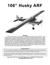
Congratulations on choosing the Eagle 2 ARF! This aircraft has been carefully engineered to pro-
vide you with all the terrific flight characteristics of the Goldberg Eagle 2 kit, a plane that has helped
thousands of R/C pilots earn their wings. Your Eagle 2 ARF's sure-footed ground handling, superb
stability, and super-slow landings will help make your early attempts at R/C flying successful. But
first, take the time to read carefully through this booklet. It will speed the assembly process, help
ensure that the plane you take to the field performs properly, and will increase your understanding of
the challenging and fun sport of R/C flying.
EAGLE 2
ARF
CARL GOLDBERG PRODUCTS, LTD.
P.O. Box 88 Oakwood GA 30566 Phone #678-450-0085 Fax # 770-53-63 www.carlgoldbergproducts.com
© Copyright 1999 Carl Goldberg Products LT.
WARNING
A radio-controlled model is not a toy and is not intended for persons under 16 years old. Keep
this kit out of the reach of younger children, as it contains parts that could be dangerous. A radio-
controlled model is capable of causing serious bodily injury and property damage. It is the buyer's
responsibility to assemble this aircraft correctly and to properly install the motor, radio, and all other
equipment. Test and fly the finished model only in the presence and with the assistance of another
experienced R/C flyer. The model must always be operated and flown using great care and common
sense, as well as in accordance with the Safety Code of the Academy of Model Aeronautics (5151
Memorial Drive, Muncie, IN 47302, 1-800-435-9262). We suggest you join the AMA and become prop-
erly insured prior to flying this model. Also, consult with the AMA or your local hobby dealer to find an
experienced instructor in your area. Per the Federal Communications Commission, you are required
to use only those radio frequencies specified "for Model Aircraft."
LIMITED WARRANTY
Carl Goldberg Products has inspected and certified the components of this aircraft. The company urges the buyer to perform his
own inspection, prior to assembly, and to immediately request a replacement of any parts he believes to be defective for their
intended use. The company warrants replacement of any such components, provided the buyer requests such replacement with-
in a period of one year from the date of purchase and provided the defective part is returned, if so requested by the company.
No other warranty, expressed or implied, is made by the company with respect to this kit. The buyer acknowledges and under-
stands that it is his responsibility to carefully assemble the finished flying model airplane and to fly it safely. The buyer hereby
assumes full responsibility for the risk and all liability for personal or property damage or injury arising out of the buyer's use of the
components of this kit.
Instructions

ITEMS NEEDED TO COMPLETE
THIS AIRCRAFT
1 RADIO GUIDANCE SYSTEM (4
CHANNEL MINIMUM REQUIRED)
1 ENGINE .40-.45 2-CYCLE, AND
MUFFLER
(a 4-cycle engine is NOT recommended)
1 CA ACCELERATOR
1 2 OZ. BOTTLE CA GLUE
1 1/2 OZ. BOTTLE CA GLUE
1 20-MINUTE EPOXY
20 #64 RUBBER BANDS
OPTIONAL
1 PIECE OF MEDIUM SANDPAPER
PAINTS FOR PILOT FIGURE &
COCKPIT
HEAT GUN OR IRON (for covering
touch-up)
1/2” FOAM RUBBER
SWITCH HARNESS
2
TOOLS AND SUPPLIES
REQUIRED FOR ASSEMBLY.
ROLL OF WAXED PAPER
MODELING OR UTILITY KNIFE
WORK SURFACE (24" x70")
ELECTRIC DRILL
1/8", 1/16", 3/32" DRILL BITS
SMALL STANDARD & PHILLIPS
SCREWDRIVERS
MASKING TAPE
NEEDLE NOSE PLIERS
YARD STICK
FLEXIBLE STRAIGHT-EDGE
30-60-90° x 6"
ENGINEERING TRIANGLE
SOFT PENCIL
A FEW STRAIGHT OR "T" PINS
ADJUSTABLE WRENCH
WIRE CUTTER (DYKES)
HAIR DRYER
(OR OPTIONAL HEAT GUN)
ACID BRUSH

ARC: Almost Ready to Cover
ARF: Almost Ready to Fly
AILERON: the control surface on the wing that rolls (or
banks) the plane
AIRFOIL: the shape of the wing as seen from the end
ANGLE OF ATTACK: the angle at which the wing meets
the air flow
BEVEL: to sand to an angle shape
BURR: the rough edges on a piece of wood or metal after
it is cut
CAP STRIP: a thin strip glued to the edges of the ribs to
shape the wing
CONTROL HORN: a device attached to each control sur-
face to provide an attachment point for the pushrod
COWL (COWLING): the nose section of the fuselage that
encloses the engine
DECALAGE: the difference between the incidence of the
wing and stabilizer
DIHEDRAL: the upward angle of the wings, as seen from
the front
ELEVATOR: the moveable part of the horizontal tail, which
controls pitch
EMPENNAGE: the tail of the plan
FIN: the fixed vertical part of the tail
FIREWALL: the plywood former at the front of the fuse-
lage, to which the engine is mounted
FORMER: a piece which shapes the fuselage; and to
which the sides of the fuselage are attached.
GUSSET: a small triangular piece glued into a corner to
strengthen it
INCIDENCE: the angle of the wing or the tail in relation to
the thrustline
LAMINATE: to glue two thin pieces of material together to
form a thicker, stronger piece
LEADING EDGE (L.E.): the front edge of the wing that
first meets the airflow
LONGERON: a stringer that runs the length of the fuse-
lage
PITCH: an up and down movement of the nose of the
plane, which is controlled by the elevator
PROTOTYPE: the full scale airplane from which the model
design was taken
PUSHROD: the long, stiff dowel or wire that connects the
servo with the control horn
RECEIVER ("Rx"): Receives radio signal
RETRACTS: (Retractable Landing Gear) devices for
extending and retracting the wheels on command
3
RTF: Ready to Fly
RIB: the airfoil-shaped piece that connects the leading
edge, spars and trailing edge of the wing together and
holds them in shape
ROLL: tilting of the plane as viewed from the front, con-
trolled by the ailerons
RUDDER: the moveable vertical tail of the plane, which
controls yaw
SERVO: the part of the airborne radio system that moves
the control surfaces
SERVO ARM (OUTPUT ARM, SERVO WHEEL): the
piece that attaches to the servo and connects it to the
pushrod
SHEAR WEB: wood sheeting that connects the top and
bottom spars to stiffen the wing
SHIM: a thin piece of wood or other material inserted
between two other pieces to improve their fit
SPAR: a wooden stick running lengthwise through the
wing that serves as its backbone
SPINNER: the rounded cone that fits over the propeller
hub
STABILIZER (STAB): the fixed horizontal part of the tail
STALL: a situation in which the plane is flying too slowly
to move sufficient air across the wing to produce lift
STRINGER: a long piece of wood attached to the formers
to shape the fuselage
THRUSTLINE: a line drawn from the center of the pro-
peller hub straight through the airplane
TORQUE: a rolling tendency caused by the spinning pro-
peller
TRAILING EDGE (T.E.): the edge of the wing that faces
the rear of the plane
TRANSMITTER ("Tx"): Transmits radio signal to servos
TRIM: small adjustments made to the control surfaces to
cause the plane to fly straight and level by itself
WASHIN: a twist in the wing that makes the trailing edge
lower than normal
WASHOUT: a twist in the wing that makes the trailing
edge higher than normal
WING SADDLE: the shaped part of the fuselage in which
the wing rests
WHEEL COLLAR: a metal ring that holds the wheel on
the axle
YAW: a right-to-left movement of the nose, controlled by
the rudder
GLOSSARY
of common modeling terms

USING THIS INSTRUCTION MANUAL
Before you begin assembling your Eagle 2
ARF, take some time to read through this entire
instruction book. It is designed to take you step-
by-step through the process and to give you
added information on engine and radio selection
and set-up, balancing your aircraft, and flying
your model. The time you spend will speed the
assembly process and help you avoid problems.
PREPARING FOR ASSEMBLY
You will need a work table of approximate-
ly 24 x 70" which has been covered to protect it
from adhesive and paint drips, as well as cuts
and other damage. Many people cover their
work area with a sheet of dry wall (sheet rock)
and/or waxed paper to prevent CA glue and
Epoxy from ruining the work surface.
4
INTRODUCTION
CONSTRUCTION TIPS
If you have never assembled a built-up
model before, the following tips will prove helpful.
IMPORTANT: ALWAYS READ A FEW
STEPS AHEAD. This will alert you to coming
instructions and will help you plan accordingly.
Using the Parts Identification section,
familiarize yourself with the various items includ-
ed in your kit box.
As you work, CHECK OFF EACH STEP
in the box provided, so that you are sure you do
not forget anything.
Do not hesitate to ask questions. Your
local hobby dealer and area flyers will most likely
by happy to help, as they want you to have a
successful flying experience. You may also
receive technical assistance from Carl Goldberg
Products via e-mail (questions@goldbergprod-
ucts.com) or by telephone 1-678-450-0085.
SELECTING RADIO CONTROL EQUIPMENT
CHOOSING A RADIO
IMPORTANT: When selecting a radio, remember
that there are many radio frequencies available,
but not all of these frequencies can be used
legally to operate model airplanes. Be sure to
tell your dealer that you want a radio with a
"Model Airplane" frequency.
Your model was designed to use a four-channel
radio. In flight, the model is controlled primarily
by using the ailerons and the elevator (see draw-
ing). One radio channel controls the aileron,
which is the primary turn control. It rolls, or
"banks" the model. Another channel operates the
elevator, which controls the pitch (climbing, level
flight, and descent). The third channel is for the
engine throttle and controls the engine speed. A
fourth channel is used for rudder, which assists
the ailerons in turning the aircraft. The new R/C
flyer probably will use the rudder only for steering
the model on the ground.
Radios are battery powered with rechargeable
nickel-cadmium batteries (ni-cads). Such sets
come equipped with a recharging unit. Also,
many of the radio systems now available feature
"servo reversing" switches which allow the pilot
to reverse the response of the servo. This fea-
ture simplifies installation and is a worthwhile
consideration when selecting a radio system.
Other radios come with a variety of sophisticated
features, such as dual rates, exponential and
control mixing, etc. These features are typically
used by more advanced flyers and are not nec-
essary for flying the Eagle 2 ARF

5
ENGINE & PROPELLER
Your plane flies well using any 2-cycle engine size from .35
to .45. (We do not recommend a 4-cycle engine for this
aircraft, due to the more complicated set-up required.) The
numbers .35 to .45 refer to the amount of space the piston
moves through inside the cylinder of the engine. This
space is called displacement; larger displacement general-
ly means more power. If you live in a hot climate, or your
flying field is approximately 3,000 feet or more above sea
level, you should stay with a .45 engine. It's a good idea to
select an engine that is popular at the flying field, so that if
you have any engine problems, other modelers will be
familiar with the engine and be able to help.
The propeller size must be matched to the engine. For
example, a .35 may use a 9" diameter prop while a .45 can
use a 10" prop. Refer to the information that is supplied
with your engine for recommended propeller sizes. It's
wise to buy a few spare props, as everyone breaks them
occasionally, and particularly often when learning to fly.
Balancing your propeller helps to protect your radio from
the damaging effects of vibration. There are good, easy to
use prop balancers on the market. Follow the instructions
that are supplied with the prop balancer. Never carve or cut
a prop near the hub for any reason (such as to fit a spin-
ner).
A 2-1/4" CGP 4-Pin Snap-On Spinner is included
in the Eagle 2 ARF. It is a rugged precision molded spin-
ner that does not require any special mounting nuts or
screws. Carefully read the spinner instructions and warn-
ings included in this book. Although a spinner helps
reduce the chance of injury from a rotating prop, extreme
caution always must be used when the engine is running.
The following equipment will be needed at the flying field
to start your engine, make adjustments, and clean your
model after flying.
FLIGHT BOX: Something sturdy in which to carry
your equipment. CGP's quick-building MiniTote carries the
basics: fuel, starter and battery, and a few essential tools.
The larger CGP SuperTote or Monster Tote are both eco-
nomical, easy to build, and pack lots of utility into little
space. They hold fuel, transmitter, starter & battery, as
well as many tools, in a balanced load that is easy to carry.
STARTING BATTERY AND GLO-PLUG CLIP: A 1-
1/2 volt battery is required to heat your engine's glo-plug
for starting. Wires connect the glo-plug clip to the battery.
Because engine starting draws a lot of electric power from
the battery, rechargeable ni-cad batteries are recommend-
ed. Although they cost more initially, they are more eco-
nomical in the long run than frequently replacing dry-cell
batteries.
FUEL: For best engine performance, use the fuel
recommended by your engine's manufacturer. 2 and 4-
cycle engines require different fuel blends. Ask your deal-
er to recommend a good quality 5-10% Nitro fuel.
FUEL PUMP: Needed to transfer fuel from the fuel
can to the model's fuel tank. A simple squeeze-type bulb
will do for small tanks, whereas manual crank or electric
pumps fill larger tanks more quickly.
FUEL LINE: Have about 3 feet of silicone fuel line
to make connections between the fuel pump, the fuel can,
and the model's fuel tank.
EXTRA PROPS: Experts always have a few
spares on hand, so flying doesn't have to stop due to a
broken propeller.

6

7
NOTE: If the covering on your aircraft has wrinkled in tran-
sit, refer to the "Covering" section earlier in this book.
1. Collect the following wing parts, as shown
above:
(1) Right wing
(1) Left wing
(3) Wing joiners
(1) Aileron servo plate
(2) Aileron servo plate supports
2. Although the control surfaces of the Eagle
ARF have been glued in at the factory, apply a drop of
Instant (thin) CA glue at each hinge location, for added
security. Allow the glue to wick into the hinge slot.
3. When dry, make sure the hinge installation
is firm by gently pulling on each hinge location.
4. Holding the three wing joiner pieces
together, with the angle cut facing up, insert them into the
joiner pockets in both the right and the left wing halves.
The joiners should fit easily in the pockets and the wing
halves should meet in the middle, with the wing dihedral
forming a broad "V".
5. Working on a protected surface, and with
paper towel handy for cleaning fingers, THOROUGHLY
mix 1-2 large (soup) spoons each from bottle A and bottle
B of 30 min. Epoxy. (Use equal amounts of each part, mix
with a stick in a plastic or paper cup or on a sheet of
waxed paper.)
6. Spread the epoxy on the three joiners and
laminate them to form a single piece. Then put additional
epoxy in each wing pocket and spread a thin layer along
one side of the entire center joint area. Immediately pro-
ceed to next step.
7. Working rapidly, so that the epoxy does
not set before you are finished, slide the laminated wing
joiner into one wing pocket and then slide the other wing
half onto the joiner until the wing halves are touching.
Wing Assembly

8
8. Using masking tape, tape the wing halves
together at the trailing edge and close to the leading edge
together, as shown. This will help keep the wing from twist-
ing.
9. Next, place additional tape at several loca-
tions across the center seam of the wing, so that the
halves stay firmly together while the epoxy is setting.
NOTE: The wing dihedral will force one side of the wing up
off the tabletop. Place a book under the high side to help
support the wing and keep the halves in the proper posi-
tion. Caution: Do not distort the wing by blocking it too high
and do not touch until the epoxy dries.
NOTE: Each radio manufacturer has its own way to mount
the servos. Therefore, read the instruction manual includ-
ed with your radio to understand exactly how the servo
should be mounted.
1. Collect the following parts:
(1) Horn bracket
(1) Servo tray
(2) ¼" sq. x 1-3/4" wood servo tray supports
(2) Snap links
(2) 7" wires threaded on one end
(1) Snap nut star tree.
(1) Servo and the necessary mounting hard
ware (grommets, brass eyelets) supplied
with the radio.
2. Place the servo tray over the servo open-
ing in the center of the wing, as shown. Trace the outline
of the servo tray.
3. Being extremely careful not to cut into the
wood underneath, cut the covering along the outline and
remove the covering in the area where the tray will fit.
4. Using CA glue, glue the servo tray sup-
ports to the bottom of the servo tray, as shown.
AILERON SERVO INSTALLATION

9
5. Gather one servo, four rubber grommets,
and four eyelets from your JR radio box. If using another
brand of radio, use the parts called for in the radio instruc-
tions.
6. Place the rubber grommets over each
mounting lug on the end of the servo. These rubber grom-
mets will prevent the lugs from breaking when the servo
moves around.
7. Working from the bottom of the mounting
lug, put an eyelet into each hole. This prevents the mount-
ing screw from being over-tightened when the servo is
mounted.
8. Place the servo into the servo-mounting
tray and enlarge the opening, if needed. Mark the location
of the mounting screws. Using a 1/16" drill bit, drill the
holes for the screws which have been supplied with your
radio. Then mount the servo into the servo tray, as shown.
9. With the servo arm positioned nearest the
trailing edge, place the servo assembly in the wing open-
ing and check the fit. Enlarge the opening, if needed. The
wire should exit under the tray, allowing the servo to fit
down into the wing. When satisfied with the fit, apply CA
glue to each tray support and glue assembly in place.
NOTE: The servo arm on the top of your servo must be
similar to the one shown in the photo above. If it is not,
choose another arm from the selection in your radio box.
Twist the servo arm until it is positioned as shown above.

10
10. Thread the mini-snap links onto the two 7"
threaded wires until the wire shows in the middle of the
snap link.
11. Thread the horn brackets on the aileron
torque rods. Be sure to screw them down until they are
flush with the top of the torque rods.
12. Referring to the above photo, install the 7"
pushrod with the snap links connecting to the horn brack-
ets.
13. To make pushrod installation easier, tape
the ailerons to the wing in the center (level) position .
14. Lay the pushrods on the top of the servo
arm and mark where the rod meets the outside hole.
15. Remove the pushrods from the horn bracket. Make
a 90° bend at the mark. Then, cut off the NON
THREADED end at approximately ½" from the
bend.
16. For ease of installation, remove the servo
arm, as shown, and take two snap nuts from the snap nut
tree.
17. Insert the pushrod through the bottom of
the servo arm and then push (snap) the snap nut on top,
to hold the pushrod is held in place. (Pliers may be help-
ful.)
18. Starting at the top of the servo opening,
press the wide white vinyl tape down over the joined wing
seam. MAKE SURE THE MIDDLE OF THE TAPE COV-
ERS THE CENTER JOINT OF THE WING, WITH HALF
OF THE TAPE ON EACH SIDE OF THE SEAM. Apply the
tape all the way around the wing, stopping at the bottom of
the servo hole. Cut off any excess tape. Peel off the clear
tape on the surface of the white tape.
19. Re-install the servo arm on the top of the
servo and reattach the push rods to the control horns. Be
sure to REMOVE THE TAPE FROM YOUR AILERONS, so
they will be able to move later, when you are setting up
your radio.
This completes your wing.

11
1. Collect the required parts.
(1) Fuselage
(1) Wing
(1) Stabilizer/Elevator assembly
(1) Fin
(1) Large control horn with nut plate attached
(2) 2-56 x ½ "screws
NOTE: Prior to assembly, the stab assembly has no top or
bottom. Use either side to begin.
2. As with the ailerons, the stab/elevator
hinges have been glued at the factory, However, for added
security, apply a drop of Instant 30 min.. (thin) CA at each
hinge location. Allow the glue to wick into the hinge slot.
When dry, check the installation by gently
pulling on each hinge location to confirm that it is secure.
3. Locate the center of the stab and mark it
at the hinge line.
With the stab assembly on end, use your
triangle to draw a line across the stab, as shown.
4. Continue the line across the elevator and
around the Leading Edge of the stab to the top side, to
help in locating the control horn.
5. Cut off the nut plate attached to the large
control horn.
6. Locate the centerline of the control horn
right over the centerline on the elevator. With a pencil,
mark the location of the holes on the base of the control
horn onto the elevator.
7. Drill a 3/32" diameter hole through the ele-
vator at each hole location.
8. Place the large control horn on the eleva-
tor and push the 2-56 x ½" screws through the holes.
TAIL ASSEMBLY & INSTALLATION
MOUNTING THE STABILIZER
Control
Horn
Nut Plate
#2-56 x 1/2”
Machine Screws

12
9. Holding the screws in place, turn the ele-
vator over and place the back plate (cut from the control
horn) over the screws. Tighten the screws, a little at a time,
until the wood just starts to dent. Set the stab aside for
now.
10. Mark a centerline down the stab platform
area, as shown. Be sure to extend the line onto the cover-
ing on top of the fuse and onto the back of the fuse, so
that you will be able to locate the center once you have put
the stab in place.
11. Using a twisting motion, insert the wing
dowels through the fuselage cabin. The dowels should
protrude an equal distance on either side of the cabin.
When satisfied with the location, glue in place.
OPTIONAL: Before flying your airplane, seal the exposed
ends of the wing dowels and any other unprotected wood
surfaces with fuel proof paint .
12. Mount the wing on the fuse, using #64
rubber bands. Measure carefully, as shown above, from
the fuselage sides out to the wing tips ("A" arrows) to be
sure the wing is centered. Then measure from the wing
tips to the back end of the fuselage ("B" arrows) to make
sure the wing is square with the fuse.
13. Using masking tape or a washable mark-
ing pen, mark the wing center at the leading and trailing
edges. Mark the top of the fuselage at the wing center-
point.
14. Using no glue, and with the control horn
pointing down, trial fit the stab onto the fuse, adjusting it as
needed to line up with the wing. Measure from the stab
tips to the fuse front ("C" arrows) to make sure the stab is
square with the fuse.
15. View the model from the rear, as shown,
to see if the stab is level, with respect to the wing. If not,
cut paper strips about ¼ x 1" and shim under the low side
until the stab is level.

13
16. When satisfied with the fit, draw match-up
lines on both the stab and the fuse to show the correct
location of the stab on the fuselage.
17. Using a sharp-bladed hobby knife, strip
covering from the stab at the points where the stab and
fuse mate, being sure to leave 1/8" to 3/16" of covering
overlap, as shown above. Erase any marks that will show
after the installation.
18. Mix epoxy as before (about 2 large spoon-
fuls), and glue the stab in place on the fuselage. Check
again to make certain the tail assembly is level and
straight. Allow epoxy to dry THOROUGHLY.
1. Collect the following parts:
(1) Fin/rudder assembly
(1) Small control horn
(2) #2-56 x ½" screws
2. Remove the wing. Add a drop of thin CA
to the fin/rudder hinges, as you have done with the aileron
and elevator hinges. When dry, CHECK TO MAKE SURE
THE HINGES ARE SECURELY GLUED by pulling gently,
but firmly, on the rudder.
3. Making sure your rudder/fin assembly is
facing the same direction as the above photo, measure up
from the bottom of the rudder ½" (12 mm.) Put a mark,
next to the hinge line, for the location of the control horn.
4. Separate the nut plate from the small con-
trol horn.
CAUTION: In the following step, take great care to avoid
cutting into the wood structure underneath the covering!
INSTALLING THE FIN

14
5. Place the control horn on the rudder, as
shown above, and mark the hole locations on the rudder,
just as was done on the elevator. Then drill 3/32" holes
and mount the control horn, screwing through the rudder to
the nut plate.
6. Slide the fin mounting posts into the top of
the fuselage and check the fit. The fin should fit easily into
each slot and should stand upright by itself. Enlarge the
holes, if necessary. When satisfied with the fit, draw lines
on both sides of the fin, showing its location on top of the
fuselage.
7. Remove the fin and carefully trim away the
covering where the fin mounts on the fuselage and stab,
being sure to avoid cutting into the wood structure
underneath.
8. Remount the fin back on the fuselage and
put a 90° triangle against the fin to make sure it is mount-
ed perpendicular to the stab.
9. When satisfied with the fit, mix up a couple
of spoonfuls of epoxy.
10. Remove the fin and apply a thin, even
coat of epoxy on the bottom of the fin and along both sides
of the fin mounting posts. Be careful not to apply too thick
a coat of epoxy, to avoid the glue squeezing out from
underneath the fin.
11. Mount the fin on the fuselage and place
the 90° triangle against the fin. Use masking tape to hold
the triangle in place until the epoxy dries. Make sure to
not glue the triangle!

15
CAUTION: The spinner, propeller, and engine, if improperly
installed, or if misused, may result in serious injury to you
or to others. Follow the spinner assembly instructions, and
other instructions and warnings elsewhere in this book,
carefully.
General Precautions:
· Never use a spinner where the cut-out is too small
for the propeller you are using.
· Follow the engine and prop mounting instructions.
· Inspect frequently, and discard any prop with nicks,
scratches, splits, cracks, or any other signs of damage.
Never repair a prop!
· Inspect for loosening and retighten using a prop
wrench.
· Make sure you and any spectators are not in the
plane of rotation of a prop.
· Protect you eyes with safety glasses.
· Get expert advice from your dealer or equipment
manufacturer, if you have any questions or concerns
regarding the spinner, engine, or propeller.
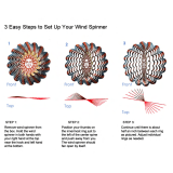
1. Open the spinner by carefully pushing a
small screwdriver (one that does not exceed the width of
the slot) straight into all four slots. DON'T TWIST! For
safety, hold the screwdriver close to the tip.
2. Examine the Retaining Pins closely for
possible tiny threads and remove.
Rub fingers around the Retaining Pins, to
give them a little lubrication.
3. "Work in" the spinner by assembling and
disassembling three or four times, rotating the pins each
time before snapping the spinner to the backplate. The
spinner will be quite stiff, at first. You may also boil it in a
pan of water for 20 minutes to rehydrate the nylon and
make it more workable.
4. Place the backplate on the engine. It
should fit snuggly. If it does not, add one of the
bushings provided, using a drop of glue to secure it, if nec-
essary.
5. Set the prop against the locator pins and
hold while tightening the nut. The prop may turn away
from the pins, as you tighten. If this happens, secure the
prop with a small drop of CA glue. If you are not satisfied
with the prop-to-spinner match-up using the locator pins,
rotate the prop 90° and adjust prop as desired.
6. Large cutouts have been molded into the
spinner for propeller clearance. Make sure the prop you
have selected has clearance all around.
INSTALLING FUSELAGE COMPONENTS
SPINNER ASSEMBLY
Push Stright Into
Slots
Finger Lube Pins
Retaining
Pin
Thread
Repeat This Sequence
Bushings Furnished
With 2” to 3” Spinners
only
Select
Best
Bushing
Bushing
Locating Pins
Clearance All Around

16
2. With the "R" facing up and on the right
side of the aircraft, as shown, place the motor mount in the
fuselage. but do not glue at this time. Position your engine
on top of the motor mount.
NOTE: The motor mount cutout will accept most stan-
dard size motors. However, if your motor is wider than
the mount, carefully trim equal amounts from both
sides of the opening, until your engine fits. Preserve
the right offset, as described above.
3. Slide the engine to the rear of the opening
until the back of the spinner has clearance of approximate-
ly 1/8".
4. When you are satisfied with the fit, use a
pencil to mark straight down through the engine mounting
holes onto the motor mount.
7. Close the spinner by positioning the
spinner with the retaining pin at the top and
squeezing the backplate onto the nose cone.
Rotate the next pin to the top and repeat, until all
four pins are secure.
8. Examine the spinner for good fit.
Make sure there is no distortion evident. Look
for a slight separation between the spinner cone
and the backplate, as shown above.
NOTE: Make sure the tail assembly is thoroughly
dry before removing the triangle and continuing.
1. Place the wooden motor mount on
your work surface, exactly as shown above. The
cut out for the motor should offset, so that there
is a little more wood in the lower the right corner.
This will give your engine right thrust. Write the
letter "R" in the upper right hand corner to mark
the top and the right side of the motor mount.
MOTOR MOUNT INSTALLATION

17
5. Remove the engine from the motor mount
and the motor mount from the fuse. At the marked hole
locations, drill four 1/8" holes through the motor mount.
HINT: Place scrap ply under the motor mount to avoid
splintering when drilling.
6. Using a toothpick, apply a drop of Vaseline
in each blind nut hole and on the top engine screw hole to
keep epoxy out of the openings.
7. Mix up approximately 2-3 spoonfuls of
epoxy and making sure the "R" is facing up, glue the motor
mount in place. The epoxy should cover all areas of con-
tact between the motor mount and the rail on which it is sit-
ting.
8. Finally, put a thin coat of epoxy over all the
wood surfaces: above and below the motor mount, on the
wood firewall, and on the fuse sides. This will protect these
areas from fuel and oil when your engine is running.
1. Collect the following items:
(1) Nosegear block
(4) 4-40 x ½ socket head screws
(4) 4-40 blind nuts
(1) # 4 washer
2. Turning fuse upside down and using the
Allen wrench supplied with this kit, screw the nosegear
block to the firewall with the 4-40 x ½" screws and the #4
washers. Screw the bolts part way until the ends are just
coming through the backside of the firewall. Refer to photo
for correct installation.
9. After the epoxy dries, permanently install
four blind nuts in the bottom of the engine mount, using
socket head screws and washers to pull the blind nuts up
into the screw holes, as shown. After tightening the blind
nuts, remove the screws.
NOSEGEAR BLOCK
INSTALLATION

18
3. Turn the fuse right side up and place the
4-40 blind nuts on the ends of the screws, with the teeth
pointed toward the firewall.
1. Collect the following items:
(2) Plywood servo trays
(3) Servos
(12) Servo rubber grommets
(12) Servo eyelets
(12) Servo screws
(1) ¼ x½ x 3-5/8 wood servo rail
2. Set up the three servos in the same man-
ner as the wing servo was prepared. Review the Wing
Assembly section of the book, if necessary. Also refer to
the specific instructions included with your radio.
3. Using Ca Glue, laminate the two plywood
servo trays together. Hold flat and allow to dry.for approxi-
mately one minute.
4. Place the servos in the tray and install with
screws, as shown. Make sure the servo arms and wheels
on your servos look approximately like the ones in the
photo. If necessary, change the arms and wheels to
match.
5. Position the ¼ x ½ x 3-5/8" wood servo
rail inside the fuselage, fitting it into the notches in the side
doublers. If the rail is too tight, sand to fit. When satisfied,
glue in place.
6. Slide the servo tray into the fuselage, plac-
ing the back of the servo tray into the notches in the rear
cabin former. After making sure the tray is straight in the
fuselage, CA glue in place by putting glue on top of the rail
and at the notches in the rear cabin former.
SERVO INSTALLATION

19
1. Collect the follow parts:
(1) Hatch hold-down
(3) #2 x 3/16" sheet metal screw
(1) Hatch cover
2. Position the hatch cover on the fuse.
Press hold-down against the front of the firewall and up
against the bottom of the hatch cover, as shown. The
"straight action" end should point towards the fuse bottom.
Tape in position on firewall.
Remove the hatch cover and apply CA
glue to the hold down. Replace the hatch cover on fuse,
gluing it to the hold-down. Allow to dry.
3. When dry, remove the hold-down/hatch
assembly from the firewall and drill two 1/16" pilot holes.
Secure the hold-down to the hatch with the two 3/16"
screws.
4. Reposition the hatch on the fuse. Mark
the location for the #2 screw and install the screw on the
firewall, as shown. Be sure to leave enough of the
unthreaded shank to engage the hold-down. Snap on and
off several times, to make sure the screw is properly
secured.
1. Collect the following parts:
(1) 1/8" x 10-1/2" nylon tube
(1) .072 x 19" threaded rod
(1) nylon mini-snap link
2. Remount the engine into the front of the
fuselage.
3. Screw the mini-snap link onto the threaded
rod.
4. Referring to the photo, start at the hole in
the right side of the firewall and slide the throttle guide
tube into the fuselage and through the upper notch on the
side of the front cabin former. The nylon guide tube should
protrude 1/8" out of the firewall as shown in the following
drawing.
HATCH INSTALLATION THROTTLE PUSHROD
INSTALLATION
#2 Shoulder Screw as Mounted in Firewall
Note: Unthreaded Shank
#2 x 3/16 Sheet
Metal Screw
#2 x 3/16 Sheet
Metal Screw
Hatch
Hold - Down
“Straight Action”
End

20
5. Referring to the drawing, and starting at
the firewall, slide the threaded rod into the nylon tube.
Connect the mini-snap link to the engine throttle arm.
6. Again referring to the drawing, move the
pushrod back and forth to simulate servo action. If the
pushrod does not move freely, adjust the wire bend where
necessary. Test the front and rear "limits" of the throttle
arm, to have a feel for what they are.
NOTE: Later, when setting the controls, make sure to set
the throttle servo linkage within the range of the throttle
arm movement.
7. Glue the nylon tube to the firewall and to
the second former.
8. Remove the servo wheel from the throttle
by removing the screw on the center of the arm and then
pulling up gently on the arm.
9. Install the push rod connector on the servo
arm as shown.
10. Guide the throttle pushrod wire though the
pushrod connector and slide the servo arm up to the throt-
tle servo.
11. Replace the servo arm on the throttle
servo and twist the servo arm clockwise until it stops.
Reposition the servo arm, as well, so that it is in the same
position as shown in the photo. Then replace the screw
into the center of the servo arm.
12. Pull the throttle pushrod back through the
untightened pushrod connector until it stops, and then
tighten the setscrew on top of the pushrod connector.
13. When the setscrew is tight, twist the throt-
tle servo arm counter-clockwise until the servo stops. Now
look at the carburetor in the front of your engine. The car-
buretor should be open (high speed) all the way, just as
shown above.
14. Now twist the throttle servo arm clockwise
until the servo stops. At this point, the carburetor should be
closed (slow speed).
NOTE: The throttle servo will be adjusted more accurately
after the radio installation.
Simulating
Servo Action
Nylon Guide Tube
Throttle Rear Limit
(usually Idle Position)
Front Limit
(usually Full
Power
Nylon Tube protrudes 1/8” Out Firewall
Pushrod
Connector
Broken View Through
Servo Wheel To Show
Installation
/