
AUTOTROL
®
740/760 CONTROL 255 & PERFORMA SERIES VALVES
(268, 268 FA)
SERVICE MANUAL
www.pentairaqua.com

TABLE OF CONTENTS
MANUAL OVERVIEW ............................................................2
SAFETY INFORMATION ........................................................ 2
LOGIX™ SERIES INSTALLER QUICK-START SHEET ............3
SYSTEM SPECIFICATIONS ...................................................6
EQUIPMENT INSTALLATION ..............................................11
SYSTEM START UP .............................................................16
PROGRAMMING .................................................................19
SERVICE AND MAINTENANCE ..........................................24
ASSEMBLY DIAGRAMS.......................................................30
TROUBLESHOOTING ..........................................................37
FLOW DIAGRAMS ............................................................... 40
FLOW DATA CHARTS ..........................................................43
MANUAL OVERVIEW
How To Use This Manual
This installation manual is designed to guide the installer
through the process of installing and starting conditioners
featuring the 700 Logix series controllers.
This manual is a reference and will not include every system
installation situation. The person installing this equipment
should have:
• Training in the 700 Logix series controllers and water
conditioner installation.
• Knowledge of water conditioning and how to determine
proper control settings.
• Adequate plumbing skills.
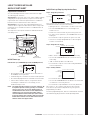
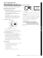
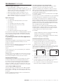
Icons That Appear In This Manual
WARNING:
Failure to follow this instruction can result in
personal injury or damage to the equipment.
CAUTION
Failure to follow this instruction can result in
damage to the equipment.
NOTE: NOTE: This will make the process easier if followed.
SAFETY INFORMATION
Electrical
There are no user-serviceable parts in the AC adapter,
motor, or controller. In the event of a failure, these should be
replaced:
• All electrical connections must be completed according
to local codes.
• Use only the power AC adapter that is supplied.
• The power outlet must be grounded.
• To disconnect power, unplug the AC adapter from its
power source.
Mechanical
• Do not use petroleum based lubricants such as
petroleum jelly, oils, or hydrocarbon based lubricants.
Use only 100% silicone lubricants.
• All plastic connections should be hand tightened.
Plumber's tape may be used on connections that do not
use an O-ring seal. Do not use pliers or pipe wrenches.
• All plumbing must be completed according to local
codes.
• Soldering near the drain line should be done before
connecting the drain line to the valve. Excessive heat will
cause interior damage to the valve.
• Do not use lead-based solder for sweat solder
connections.
• The drain line must be a minimum of 1/2" diameter. Use
3/4" pipe if the backwash flow rate is greater than 5 GPM
(18.9 Lpm) or the pipe length is greater than 20 feet (6
m).
• Do not support the weight of the system on the control
valve fittings, plumbing, or the bypass.
General
• Keep the media tank in the upright position. Do not turn
on side, upside down, or drop. Turning the tank upside
down will cause media to enter the valve.
• Operating ambient temperature is between 34ºF (1ºC)
and 120ºF (49ºC).
• Operating water temperature is between 34ºF (1ºF) and
100ºF (38ºC).
• Working water pressure range is 20 to 125 psi (1.38
to 8.61 bar). In Canada the acceptable working water
pressure range is 20 to 100 psi (1.38 to 6.89 bar).
• Use only regenerant salts designed for water softening.
Do not use ice melting, block, or rock salts.
• Follow state and local codes for water testing. Do not use
water that is micro-biologically unsafe or of unknown
quality.
• When filling media tank, do not open water valve
completely. Fill tank slowly to prevent media from exiting
the tank.
• When installing the water connection (bypass or
manifold) connect to the plumbing system first. Allow
heated parts to cool and cemented parts to set before
installing any plastic parts. Do not get primer or solvent
on O-rings, nuts, or the valve.
CALIFORNIA PROPOSITION 65 WARNING
WARNING:
This product contains chemicals known to the
State of California to cause cancer or birth
defects or other reproductive harm.
2 •AUTOTROL
®
740/760 Control 255 & Performa Series Valves (268, 268FA) Service Manual

LOGIX™ SERIES INSTALLER
QUICKSTART SHEET
Logix Series Controllers
See: Determining If You Have a 740 or 760 Control on page
19 to identify your controller.
740 Controller - Electronic time clock control capable of doing
7-day (day of week) regeneration, or up to a 99 interval day
regeneration. This control will operate both in a conditioner
(softener) or filter mode with the same controller.
760 Controller - Electronic metered-demand (volumetric)
controller which regenerates based on the water usage of the
installation site. A calendar override is a standard feature on
this controller.
The Logix Series will operate on both the 255 and Performa
valve body series.
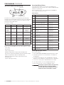
Time & Day
Regen Time & Day
Salt
SU MO TU WE TH FR SA DAYS
LBS
PM
MIN
KG
x100
x2
P
HC
Capacity
Hardness
LCD Display
DOWN Button
SET Button
UP Button
Manual
Regeneration
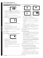
Initial Power-up
Initial Power Up - (CAMSHAFT proceeds to HOME position)
Time & Day
Regen
Time & Day
Salt
Capacity
Hardness
SU MO TU WE TH FR SA DAYS
• At initial power-up, the camshaft will need to rotate to
the HOME (in service) position.
• Camshaft may take 1-2 minutes to return to home position.
• Err 3 will be displayed until the camshaft returns to home.
• If more than 2 minutes elapses, verify that the motor
is turning the camshaft. If it is not turning, see the
troubleshooting section.
NOTE: The Logix controller features a self-test sequence. At
first power-up of the control, you may see a number
such as 1.00, 1.02, 1.04, or 2.00, displayed. This is
an indication that the self-test is not completed. To
complete the test, verify that the turbine cable is
connected. Blow into the turbine port (valve outlet)
to spin the turbine. The controller will verify that the
turbine works and the self test will finish. Proceed
with the initial start up procedure.
Initial Start-up Step-by-step Instructions
Step 1: Program System Size
Time & Day
Regen
Time & Day
Salt
SU MO TU WE TH FR SA DAYS
Capacity
Hardness
Time & Day
Regen
Time & Day
Salt
SU MO TU WE TH FR SA DAYS
Capacity
Hardness
This step may have been performed by your system’s OEM
manufacturer. In this case, proceed to step 2.
• Input system size - resin volume - in cubic feet or liters.
• Use UP and DOWN buttons to scroll through resin
volume choices.
• Choose the nearest volume to your actual system size.
• To choose a filter operation - press DOWN until an "F" is
displayed.
• Press SET to accept the system size you’ve selected.
• If incorrect setting is programmed, see "Resetting the
Control" section below.
Step 2: Program Time of Day
Time & Da
y
SU MO TU WE TH FR SA DAYS
Capacity
Hardness
• While "12:00" is blinking, set the correct time of day.
• Use the UP and DOWN buttons to scroll to the correct
time of day.
• "PM" is indicated, "AM" is not indicated.
• Press SET to accept the correct time of day and advance
to the next parameter.
Step 3: Set Day of Week
Time & Day
Regen
Time & Day
Salt
SU MO TU WE TH
FR
SA DA
YS
Capacity
Hardness
• Press SET to make the arrow under SU flash.
• Use the UP and DOWN buttons to advance the arrow until
it is under the correct day of week.
• Press SET to accept and advance to the next parameter.
After steps 1-3, the controller will operate most systems.
Proceed to step 4 if further adjustments to your system’s
programming is needed.
To exit the programming state, wait 30 seconds and the controller
will automatically put you into the normal operating mode.
AUTOTROL
®
740/760 Control 255 & Performa Series Valves (268, 268FA) Service Manual • 3
QUICK START

Step 4: Set Regen Time
Time & Day
Regen
Time & Day
Salt
SU MO TU WE TH FR SA DAYS
Capacity
Hardness
• 2:00 (AM) is the default time of regeneration. To accept
this time, press the DOWN button to move to step 5.
• To change the regen time, press SET - causing 2:00 to flash.
• Use the UP and DOWN buttons to advance to the desired
regen time.
• Press SET to accept the time and advance to the
next parameter.
Step 5: Set Days to Regenerate (740 Time-clock Control Only)
Time & Day
Regen
Time & Day
Salt
SU MO TU WE TH FR SA DAYS
Capacity
Hardness
• If using 760 control - proceed to step 5a.
• Set number of days between time-clock regeneration
(regen frequency).
• Default time is 3 days.
• Days can be adjusted from 1/2 (.5) to 99 days.
• To change, press SET to make the "3" flash.
• Use the UP and DOWN buttons to change to the number
of days desired.
• Press SET to accept the regen frequency, and advance to
the next cycle.
To use the 7-day timer option - see full Dealer
Installation Manual.
Step 5a: Set Calendar Override (760 Demand Control Only)
Time & Day
Regen
Time & Day
Salt
SU MO TU WE TH FR SA DAYS
Capacity
Hardness
• If using 740 control - proceed to step 7.
• Set number of days for calendar override on
demand control.
• "0" days is the default for calendar override.
• Days can be adjusted from 1/2 (.5) to 99 days.
• To change, press SET to make the "0" flash.
• Use the UP or DOWN buttons to change to the number of
days desired.
• Press SET to accept the regen frequency, and advance to
the next cycle.
LOGIX™ SERIES INSTALLER
QUICKSTART SHEET CONTINUED
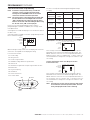
Step 6: Amount of Regenerant used per Regeneration
Time & Day
Regen
Time & Day
Salt Amount
SU MO TU WE TH FR SA DAYS
Capacity
Hardness
Time & Day
Regen
Time & Day
Salt Amount
SU MO TU WE TH FR SA DAYS
Capacity
Hardness
Standard Setting High Capacity Setting
Time & Day
Regen
Time & Day
Salt Amount
SU MO TU WE TH FR SA DAYS
Capacity
Hardness
KG
Time & Day
Regen
Time & Day
Salt
SU MO TU WE TH FR SA DAYS
Capacity
Hardness
Low Setting (High Efficiency)
• Set desired regenerant amount.
• Default setting is "S" standard salting.
• 3 salt settings are available on 740 and 760 controls:
S – Standard Salt – 9 lbs/cubic foot of resin (120 grams/
liter of resin)
H – High Salt – 15 lbs/cubic foot of resin (200 grams/liter
of resin)
L – Low Salt – 3 lbs/cubic foot of resin (40 grams/liter
of resin)
• Low Salt is the "Highly Efficient Mode".
• To change salt setting, press the SET button and use the
UP and DOWN buttons to change to the desired setting.
• Press SET to accept the setting and advance to the
next parameter.
See Dealer Installation Manual for more complete information
on :salt settings for different system sizes, capacities and
expected efficiencies.
Step 7: Estimated Capacity
• System capacity is displayed in total kilograins or kilograms
of hardness removed before a regeneration is necessary.
• Value is derived from the system’s resin volume input,
and salt amount input.
• The capacity displayed is a suggested value - as
recommended by resin manufacturers.
• Capacity is only displayed for information purposes on
740 control - it does not (and cannot) need to be changed.
• To change capacity on 760 control, press SET to make the
default capacity flash. Use the UP and DOWN buttons to
increment to the desired capacity.
• Press SET to accept the setting and advance to the
next parameter.
If using 740 control, programming is complete. The control will
return you to the normal operation mode.
Step 8: Enter Hardness (760 Demand Control Only)
• Enter inlet water hardness at installation site.
• Default hardness setting is 25 grains (25 ppm for metric).
• To change hardness, press SET to make the setting flash.
Use the UP and DOWN buttons to scroll to the
correct hardness.
• Press SET to accept the entered hardness value.
• The control will return you to the normal operation mode
Initial system programming is now complete. The control will
return to normal operation mode, if a button is not pushed for
30 seconds.
4 •AUTOTROL
®
740/760 Control 255 & Performa Series Valves (268, 268FA) Service Manual
QUICK START

LOGIX™ SERIES INSTALLER
QUICKSTART SHEET CONTINUED
For system start-up procedure, including: purging the mineral
tank, refilling the regenerant tank, and drawing regenerant,
see the Initial Startup Step-By-Step Instructions on page 16.
Manual Regeneration Procedures
To Initiate a Manual Regeneration:
• Press REGEN once for delayed regeneration. System will
regenerate at next set regen time (2:00 AM). A flashing
regen (recycle) symbol will be displayed.
• Press and hold REGEN for 5 seconds to initiate
immediate manual regeneration. A solid regen symbol
will be displayed.
• After immediate regeneration has begun, press
REGEN again to initiate a second manual regeneration.
An X2 symbol will be displayed, indicating a second
regeneration will follow the first regeneration.
During a Regeneration:
Second Manual
Regen Symbol
Time & Day
Regen
Time & Day
Salt
SU MO TU WE TH FR SA DAYS
C
Capacity
Hardness
MIN
x2
Regen Symbol
Cycle Indicator
• A "C#" is displayed to show current cycle.
• Total regen time remaining is displayed on screen.
• Press and hold SET to show current cycle time remaining.
To Advance Regeneration Cycles:
• Press and hold SET - showing current cycle time.
• Simultaneously press SET and UP to advance one cycle.
An hourglass will display while cam is advancing. When
cam reaches next cycle, "C2" will be displayed.
• Repeat SET and UP to advance through each cycle.
• Press and hold SET and UP buttons for 5 seconds to
cancel regen. Hourglass will begin flashing, indicating
regen is cancelled. Camshaft will advance to home - may
take 1-2 minutes.
Regeneration Cycles:
• C1 - Backwash
• C2 - Regenerant Draw/Slow Rinse (not used in filter mode)
• C3 - Slow Rinse (not used in filter mode)
• C4 - System Pause (to repressurize tank)
• C5 - Fast rinse cycle 1
• C6 - Backwash cycle 2
• C7 - Fast Rinse cycle 2
• C8 - Regenerant refill (not used in filter mode)
Resetting The Control
Time & Day
Regen
Time & Day
Salt
SU MO TU WE TH FR SA DAYS
H
Capacity
Hardness
Time & Day
Regen
Time & Day
Salt
SU MO TU WE TH FR SA DAYS
Capacity
Hardness
Resetting the Logix
Controller
Unprogrammed control after
reset
To reset the control:
1. Press and hold SET and DOWN simultaneously for 5 seconds.
2. H0 and the system’s set resin volume (or "F" mode) will
be displayed.
3. If a history value other than "H0" is displayed, use the up
arrow to scroll through the settings until "H0" is displayed.
4. To reset the control, press and hold SET for 5 seconds.
5. The control will be reset to an unprogrammed state.
6. Go to "Initial Set-up" section of this sheet to
reprogram control.
WARNING:
Resetting the control will delete all
information stored in its memory. This
will require you to reprogram the control
completely from the initial power up mode.
Further programming or set-up instructions can be found in
this manual.
AUTOTROL
®
740/760 Control 255 & Performa Series Valves (268, 268FA) Service Manual • 5
QUICK START

SYSTEM SPECIFICATIONS
T
E
S
T
E
D
A
N
D
C
E
R
T
I
F
I
E
D
U
N
D
E
R
I
N
D
U
S
T
R
Y
S
T
A
N
D
A
R
D
S
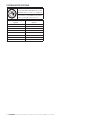
The systems below have been Tested and
Certified by WQA to NSF/ANSI Std. 44 and
NSF/ANSI 372 for “Lead Free” compliance.
The 255 valve and 268 valve have been
Tested and Certified by WQA to NSF/ANSI
Std 61 Section 8 Mechanical Devices.
WQA Certified 255 Valve
Systems
WQA Certified 268 Valve
Systems
255-740-075-844 268-740-948
255-740-100-948 268-740-150-1054
255-740-100-1040 268-740-200-1248
255-740-150-1054 268-760-948
255-760-075-844 268-760-150-1054
255-760-100-948 268-760-200-1248
255-760-100-1040
255-760-150-1054
6 •AUTOTROL
®
740/760 Control 255 & Performa Series Valves (268, 268FA) Service Manual

Pentair Residential Filtration, LLC 12/4/12
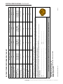
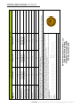
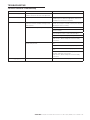
WATER SOFTENER PERFORMANCE DATA SHEET
Model 255-740-075-844 255-740-100-948 255-740-100-1040 255-740-150-1054
Rated Service Flow (gpm) 6.0 10.0 11.0 10.4
Pressure Drop at Rated
Service Flow Rate (psi)
8.0 15.0 14.0 15.0
Rated Capacity
(grains @ lb. of salt)
10, 719 @ 2.65
22,110 @ 6.75
25,503 @ 11.25
14,293 @ 3.5
29,480 @ 9.0
34,004 @ 15.0
12,163 @ 3.5
25,087 @ 9.0
28,937 @ 15.0
21,439 @ 5.25
44,220 @ 13.5
51,006 @ 22.5
Rated Efficiency
(grains/lb Salt @ lb. of salt)
Not Applicable. Not Applicable Not Applicable Not Applicable
Maximum Flow Rate During
Regeneration (gpm)
1.7 2.1 2.7 2.7
Sybron C-249NS
Ion Exchange Resin (cu ft)
0.75 1.0 1.0 1.5
Backwash - GPM 1.7 2.1 2.7 2.7
Rapid Rinse/purge - GPM
1.7 2.1 2.7 2.7
Operating Presssure:20 -125 psi or 1.4 – 8.8 kg/Centimeter
2
, Operating Temperature: 34 - 100° F or 1.1 – 38° C,
Acceptable Salt Type: Sodium Chloride – Pellet or solar salt for water softeners
All Systems above tested at 35psi +/- 5 psi, pH of 7.5 +/- 0.5, Capacity Testing Flow Rate = 50% of the rated service flow rate for the various size systems.
These water softener systems have been tested by WQA and conform to NSF/ANSI 44 for specific performance claims as verified and substantiated by test data. These
systems are not intended to be used for treating water that is microbiologically unsafe or of unknown quality without adequate disinfection before or after the system. Refer to
the system Installation and Service Manuals for set-up and programming instructions.
Contact your local Autotrol dealer for parts and service. See your owner’s manual for warranty information.
Important Notice: For conditions of use, health claims certified by the California Department of Public Health and replacement parts, see product data sheet
Iowa Requirement:
Seller: ______________________________________________________________ Date: _________________________
Buyer: ______________________________________________________________ Date: _________________________
Tested and Certified by WQA against NSF/ANSI Standard 44 & NSF/ANSI 372 for “lead free” compliance.
The valve used on this unit is Tested and Certified by WQA to NSF/ANSI Std. 61 Section 8 for Material Safety Only
PENTAIR Residential Filtration, LLC
5730 North Glen Park Road Milwaukee, Wisconsin 53209
PHONE: (262)-238-4400
SYSTEM SPECIFICATIONS CONTINUED
AUTOTROL
®
740/760 Control 255 & Performa Series Valves (268, 268FA) Service Manual • 7

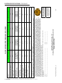
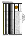
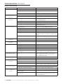
WATER SOFTENER PERFORMANCE DATA SHEET
Model
255-760-075-844 255-760-100-948 255-760-100-1040 255-760-150-1054
Rated Service Flow (gpm) 6.0 10.1 10.7 10.0
Pressure Drop at Rated Service
Flow Rate (psi)
8.0 15.0 13.0 14.0
Rated Capacity
(grains @ lbs. of salt)
10, 719 @ 2.65
22,110 @ 6.75
25,503 @ 11.25
14,293 @ 3.5
29,480 @ 9.0
34,004 @ 15.0
12,163 @ 3.5
25,087 @ 9.0
28,937 @ 15.0
21,439 @ 5.25
44,220 @ 13.5
51,006 @ 22.5
Rated Efficiency
(grains/lb Salt @ lb. of salt)
4,083/lb. salt @ 2.65 lbs. 4,083/lb. salt @ 3.5 lbs. 3,475/lb. salt @ 3.5 lbs. 4,083/lb. salt @ 5.25 lbs.
Maximum Flow Rate During
Regeneration (gpm)
1.7 2.1 2.7 2.7
Sybron C-249NS
Ion Exchange Resin (cu ft)
0.75 1.0 1.0 1.5
Backwash - GPM 1.7 2.1 2.7 2.7
Rapid Rinse/purge - GPM
1.7 2.1 2.7 2.7
Operating Pressure: 20 -125 psi or 1.4 – 8.8 kg/Centimeter
2
, Operating Temperature: 34 - 100° F or 1.1 – 38° C
Acceptable Salt Type: Sodium Chloride – Pellet or solar salt for water softeners
All Systems above tested at 35psi +/- 5 psi, pH of 7.5 +/- 0.5, Capacity Testing Flow Rate = 50% of the rated service flow rate for the various size systems.
Tested and Certified by
WQA against NSF/ANSI
Standard 44 & NSF/ANSI 372
for “lead free” compliance.
These water softener systems have been tested by WQA and conform to NSF/ANSI 44 for specific performance claims as verified and substantiated by test data. The rated salt efficiencies above
were also determined in accordance with NSF/ANSI 44 and are only valid at the salt dosage referenced above. An efficiency rated water softener is a demand initiated regeneration (DIR) softener
which also complies with specific performance specifications intended to minimize the amount of regenerant brine and water used in its operation. Efficiency rated water softeners shall have a rated
salt efficiency of not less that 3350 grains of total hardness exchanged per pound of salt (based on NaCl equivalency) (477 grams of total hardness exchanged per kilogram of salt), and shall not
deliver more salt than its listed rating. The rated efficiency of the water softener, the salt dosage at that efficiency, the capacity at that salt dosage and that of the efficiency is only valid at the stated salt
dosage. Efficiency is measured by a laboratory test described in NSF/ANSI 44. The test represents the maximum possible efficiency the system can achieve. Operational efficiency is the actual
efficiency achieved after the system has been installed. It is typically less than the efficiency due to individual application factors including water hardness, water usage, and other contaminants that
reduce the water softener’s capacity. These systems are not intended to be used for treating water that is microbiologically unsafe or of unknown quality without adequate disinfection before or after
the system. Refer to the system Installation and Service Manuals for set-up and programming instructions.
Contact your local Autotrol dealer for parts and service. See your owner’s manual for warranty information.
Important Notice: For conditions of use, health claims certified by the California Department of Public Health and replacement parts, see product data sheet
Iowa Requirement:
Seller: ______________________________________________________________ Date: _________________________
Buyer: ______________________________________________________________ Date: _________________________
The valve used on this unit is
Tested and Certified by WQA
to NSF/ANSI Std. 61 Section 8
for Material Safety Only
PENTAIR Residential Filtration, LLC
5730 North Glen Park Road Milwaukee, Wisconsin 53209
PHONE: (262)-238-4400
Pentair Residential Filtration, LLC 3/2/11
SYSTEM SPECIFICATIONS CONTINUED
8 •AUTOTROL
®
740/760 Control 255 & Performa Series Valves (268, 268FA) Service Manual

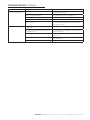
268-740 Valve Series Water Softener System Performance Data Sheet
Model
268-740-100-948
268-740-150-1054
268-740-200-1248
Rated Service Flow (gpm)
11.0 12.7 15.0
Pressure Drop at Rated
Service Flow Rate (psi)
12.9 15.4 14.4
Rated Capacity
(grains @ lb of salt)
14,038 @ 3.3
27,770 @ 9.0
33,418 @ 15.0
21,411 @ 4.95
42,354 @ 13.5
50,968 @ 15.0
28,548 @ 6.6
56,472 @ 18.0
67,958 @ 30.0
Rated Efficiency
(grains/lb Salt @ lb of salt)
Not Applicable Not Applicable Not Applicable
Maximum Flow Rate During
Regeneration (gpm)
5.5 5.5 5.5
Sybron C-249NS
Ion Exchange Resin (cu ft)
1.0 1.5 2.0
Tank Size
9” x 48” 10” x 54” 12” x 48”
Backwash - GPM
2.1 2.7 3.9
Rapid Rinse/purge - GPM
5.5 5.5 5.5
Operating Pressure:20 -125 psi or 1.4 – 8.8 kg/Centimeter
2
, Operating Temperature: 34 - 100° F or 1.1 – 38° C
Acceptable Salt Type: Sodium Chloride – Pellet or solar salt water softeners
All Systems above tested at 35psi +/- 5 psi, pH of 7.5 +/- 0.5, Capacity Testing Flow Rate = 50% of the rated service flow rate for the various size systems.
These water softener systems have been tested by WQA and conform to NSF/ANSI 44 for specific performance claims as verified and substantiated by
test data. These systems are not intended to be used for treating water that is microbiologically unsafe or of unknown quality without adequate disinfection
before or after the system. Refer to the system Installation and Service Manuals for set-up and programming instructions.
Contact your local dealer for parts and service. See your owner’s manual for warrant information
Important Notice: For conditions of use, health claims certified by the California Department of Public Health and replacement parts, see product data sheet
Iowa Requirement:
Seller: ______________________________________________________________ Date: _________________________
Buyer: ______________________________________________________________ Date: _________________________
12/4/12
Tested and Certified by WQA against NSF/ANSI Std. 44 & 372 for “lead free” compliance.
The valve used on this unit is Tested and Certified by WQA to NSF/ANSI Std. 61 Section 8 for Material Safety Only
PENTAIR Residential Filtration, LLC
5730 North Glen Park Road
Milwaukee, Wisconsin 53209
PHONE: (262)-238-4400
SYSTEM SPECIFICATIONS CONTINUED
AUTOTROL
®
740/760 Control 255 & Performa Series Valves (268, 268FA) Service Manual • 9

268-760 Valve Series Water Softener System Performance Data Sheet
Model
268-760-100-948
268-760-150-1054
268-760-200-1248
Rated Service Flow (gpm)
10.0 12.7 15.0
Pressure Drop at Rated
Service Flow Rate (psi)
12.9 15.4 14.4
Rated Capacity
(grains @ lb of salt)
14,274 @ 3.3
28,236 @ 9.0
33,979 @ 15.0
21,411 @ 4.95
42,354 @ 13.5
50,968 @ 15.0
28,548 @ 6.6
56,472 @ 18.0
67,958 @ 30.0
Rated Efficiency
(grains/lb Salt @ lb of salt)
4,325 /lb. salt @ 3.3 lbs. 4,325/lb. salt @ 4.95 lbs. 4,325/lb. salt @ 6.6 lbs.
Maximum Flow Rate During
Regeneration (gpm)
5.5 5.5 5.5
Sybron C-249NS
Ion Exchange Resin (cu ft)
1.0 1.5 2.0
Tank Size
9” x 48” 10” x 54” 12” x 48”
Backwash - GPM
2.1 2.7 3.9
Rapid Rinse/purge - GPM
5.5 5.5 5.5
Operating Pressure:20 -125 psi or 1.4 – 8.8 kg/Centimeter
2
, Operating Temperature: 34 - 100° F or 1.1 – 38° C
Acceptable Salt Type: Sodium Chloride – Pellet or solar salt for water softeners
All Systems above tested at 35psi +/- 5 psi, pH of 7.5+/- 0.5, Capacity Testing Flow Rate = 50% of the rated service flow rate for the various size systems.
Tested and Certified by WQA against NSF/ANSI
Std. 44 & 372 for “lead free” compliance.
These water softener systems have been tested by WQA and conform to NSF/ANSI 44 for specific performance claims as verified and substantiated by
test data. The rated salt efficiencies above were also determined in accordance with NSF/ANSI 44 and are only valid at the salt dosage referenced above.
An efficiency rated water softener is a demand initiated regeneration (DIR) softener which also complies with specific performance specifications intended
to minimize the amount of regenerant brine and water used in its operation. Efficiency rated water softeners shall have a rated salt efficiency of not less
that 3350 grains of total hardness exchanged per pound of salt (based on NaCl equivalency) (477 grams of total hardness exchanged per kilogram of salt),
and shall not deliver more salt than its listed rating. The rated efficiency of the water softener, the salt dosage at that efficiency, the capacity at that salt
dosage and that of the efficiency is only valid at the stated salt dosage. Efficiency is measured by a laboratory test described in NSF/ANSI 44. The test
represents the maximum possible efficiency the system can achieve. Operational efficiency is the actual efficiency achieved after the system has been
installed. It is typically less than the efficiency due to individual application factors including water hardness, water usage, and other contaminants that
reduce the water softener’s capacity. These systems are not intended to be used for treating water that is microbiologically unsafe or of unknown quality
without adequate disinfection before or after the system. Refer to the system Installation and Service Manuals for set-up and programming instructions.
Contact your local dealer for parts and service. See your owner’s manual for warranty information.
Important Notice: For conditions of use, health claims certified by the California Department of Public Health and replacement parts, see product data sheet
Iowa Requirement:
Seller: ______________________________________________________________ Date: _________________________
Buyer: ______________________________________________________________ Date: _________________________
7/16/10
The valve used on this unit is Tested and Certified
by WQA to NSF/ANSI Std. 61 Section 8 for
Material Safety Only
PENTAIR Residential Filtration, LLC
5730 North Glen Park Road
Milwaukee, Wisconsin 53209
PHONE: (262)-238-4400
SYSTEM SPECIFICATIONS CONTINUED
10 •AUTOTROL
®
740/760 Control 255 & Performa Series Valves (268, 268FA) Service Manual

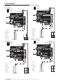
EQUIPMENT INSTALLATION
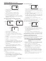
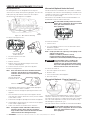
System Regeneration Cycles
1. Service (Downflow) — Cycle C0:
Untreated water is directed down through the resin bed and up
through the riser tube. The hardness ions attach themselves
to the resin and are removed from the water. The water is
conditioned as it passes through the resin bed.
2. Backwash (Upflow) — Cycles C1, C6:
The flow of water is reversed by the control valve and directed
down the riser tube and up through the resin bed. During the
backwash cycle, the bed is expanded and debris is flushed to
the drain.
3. Brine/Slow Rinse (Downflow) — Cycles C2, C3:
The control directs water through the brine injector and brine
is drawn from the regenerant tank. The brine is then directed
down through the resin bed and up through the riser tube to
the drain. The hardness ions are displaced by sodium ions and
are sent to the drain. The resin is regenerated during the brine
cycle. Brine draw is completed when the air check closes.
4. Repressurize Cycle — (Hard Water Bypass Flapper
Open), Cycle C4:
This cycle closes the flappers for a short time to allow the
air and water to hydraulically balance in the valve before
continuing the regeneration.
5. Fast Rinse (Downflow) — Cycles C5, C7:
The control directs water down through the resin bed and
up through the riser tube to the drain. Any remaining brine
residual is rinsed from the resin bed.
6. Brine Refill — Cycle C8:
Brine refill occurs during a portion of the fast rinse cycle.
Water is directed to the regenerant tank at a controlled rate, to
create brine for the next regeneration.
SERVICE BACKWASH BRINE/SLOW RINSE
FAST RINSE
From Regenerant
Tank
To Regenerant
Tank
BRINE REFILL
REPRESSURIZE
C0 C1 and C6 C2 and C3
C4 C5 and C7 C8
Figure 1
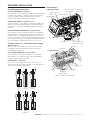
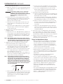
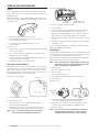
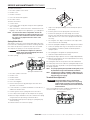
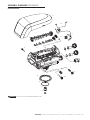
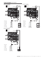
Valve Features
Optical Sensor
One Piece Valve
Disc Spring
Refill ControllerControl
Module Mount
Check Ball
Injector and Cap
Regenerant Tank
Tube Connection
Manifold
Connection
Air Check
Right Side 255 Valve
Left Side 255 Valve
Motor
Camshaft
Backwash
Drain Control
Valve Discs
Locking Bar
Inlet
Drain
Injector Screen
Filter
Outlet
Figure 2 255 Valve Identification
AUTOTROL
®
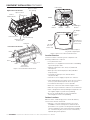
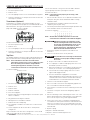
740/760 Control 255 & Performa Series Valves (268, 268FA) Service Manual • 11

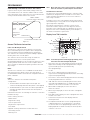
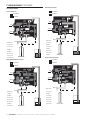
Optical Sensor
One Piece Valve
Disc Spring
Refill Controller
Control
Module Mount
Injector and Cap
Regenerant Tube
Connection
Right Side Performa Valve
Valve Discs
Left Side Performa Valve
Motor
Camshaft
Backwash
Drain Control
Inlet
Drain
Injector Screen
Filter
Outlet
Figure 3 Performa Valve Identification
EQUIPMENT INSTALLATION CONTINUED
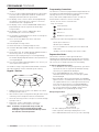
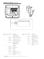
Front
Time & Day
Regen Time & Day
Salt
SU MO TU WE TH FR SA DAYS
LBS
PM
MIN
KG
x100
x2
P
HC
Capacity
Hardness
LCD Display
Manual Regen
Button
Down
Button
Set
Button
Up
Button
Back
AC Adapter
(low
voltage)
Input
Main Motor &
Optical Sensor
Connection
No Salt
Detector
Connection
740/760 Turbine Input or
Dry Contact Signal Input
Figure 4 700 Series Controller Identification
Location Selection
Location of a water treatment system is important. The
following conditions are required:
• Level platform or floor
• Room to access equipment for maintenance and adding
regenerant (salt) to tank.
• Ambient temperatures over 34°F (1°C) and below
120°F (49°C).
• Water pressure below 125 psi (8.61 bar) and above
20 psi (1.4 bar).
• In Canada the water pressure must be below
100 psi (6.89 bar).
• Constant electrical supply to operate the controller.
• Total minimum pipe run to water heater of ten feet (three
meters) to prevent backup of hot water into system.
• Local drain for discharge as close as possible.
• Water line connections with shutoff or bypass valves.
• Must meet any local and state codes for site of installation.
• Valve is designed for minor plumbing misalignments. Do
not support weight of system on the plumbing.
• Be sure all soldered pipes are fully cooled before
attaching plastic valve to the plumbing.
Outdoor Locations
When the water conditioning system is installed outdoors,
several items must be considered.
• Moisture — The valve and 700 controller are rated
for NEMA 3 locations. Falling water should not affect
performance. The system is not designed to withstand
extreme humidity or water spray from below. Examples
are: constant heavy mist, near corrosive environment,
upwards spray from sprinkler.
12 •AUTOTROL
®
740/760 Control 255 & Performa Series Valves (268, 268FA) Service Manual

EQUIPMENT INSTALLATION CONTINUED
• Direct Sunlight — The materials used will fade or
discolor over time in direct sunlight. The integrity of the
materials will not degrade to cause system failures. If it
is necessary to locate the conditioner in direct sunlight, a
protective outdoor cover (P/N 1267811) over the valve and
controller is necessary.
• Temperature — Extreme hot or cold temperatures
may cause damage to the valve or controller. Freezing
temperatures will freeze the water in the valve. This will
cause physical damage to the internal parts as well as the
plumbing. High temperatures will affect the controller.
The display may become unreadable but the controller
should continue to function. When the temperature drops
down into normal operating limits the display will return
to normal. A protective cover (P/N 1267811) should assist
with high temperature applications.
• Insects — The controller and valve have been designed to
keep all but the smallest insects out of the critical areas.
Any holes in the top plate can be covered with a metal
foil duct work tape. The top cover should be installed
securely in place.
• Wind — The Logix cover is designed to withstand a 30
mph (48 Kph) wind when properly installed on the valve.
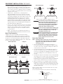
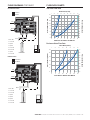
Water Line Connection
A bypass valve system should be installed on all water
conditioning systems. Bypass valves isolate the conditioner
from the water system and allow unconditioned water to be
used. Service or routine maintenance procedures may also
require that the system is bypassed. Figures 5, 6, and 7 show
the three common bypass methods.
Normal Operation In Bypass
In
B
Y
P
A
S
S
B
Y
P
A
S
S
Out
B
Y
P
A
S
S
B
Y
P
A
S
S
In Out
Figure 5 Series 256 bypass for use with 255 valve body
B
Y
P
A
S
B
Y
P
A
S
B
Y
P
A
S
B
Y
P
A
S
Water Conditioner
Normal Operation In Bypass
In
Out
In Out
Water Conditioner
Figure 6 Series 1265 bypass for use with
Performa valve bodies
Water
Conditioner
Water
Conditioner
Water Conditioner
Normal Operation In Bypass
Water Conditioner
Figure 7 Typical Globe Valve Bypass System
WARNING:
The inlet water must be connected to the inlet
port of the valve. When replacing non-Pentair
Water valves, the inlet and outlet may be
reversed. It is also possible for the plumbing
to be installed in an opposite order. Do not
solder pipes with lead-based solder.
WARNING:
Do not use tools to tighten plastic fittings. Over
time, stress may break the connections. When
the 1265 or 256 bypass valve is used, only
hand tighten the plastic nuts.
WARNING:
Do not use petroleum grease on gaskets when
connecting bypass plumbing. Use only 100%
silicone grease products when installing any
plastic valve. Non-silicone grease may cause
plastic components to fail over time.
Drain Line Connection
NOTE: Standard commercial practices are expressed here.
Local codes may require changes to the following
suggestions. Check with local authorities before
installing a system.
1. The unit should be above and not more than 20 feet
(6.1 m) from the drain. Use an appropriate adapter fitting
to connect 1/2 inch (1.3 cm) plastic tubing to the drain line
connection of the control valve.
2. If the backwash flow rate exceeds 5 gpm (22.7 Lpm) or if
the unit is located 20-40 feet (6.1-12.2 m) from drain, use
3/4 inch (1.9 cm) tubing. Use appropriate fittings to connect
the 3/4 inch tubing to the 3/4 inch NPT drain connection
on valve.
3. The drain line may be elevated up to 6 feet (1.8 m) providing
the run does not exceed 15 feet (4.6 m) and water pressure
at the conditioner is not less than 40 psi (2.76 bar).
Elevation can increase by 2 feet (61 cm) for each additional
10 psi (.69 bar) of water pressure at the drain connector.
4. Where the drain line is elevated but empties into a drain
below the level of the control valve, form a 7 inch (18 cm)
loop at the far end of the line so that the bottom of the loop
is level with the drain line connection. This will provide an
adequate siphon trap.
Where the drain empties into an overhead sewer line, a sink-
type trap must be used.
Secure the end of the drain line to prevent it from moving.
Right Way
Air Gap
Drain
Figure 8 Drain Line Connection
AUTOTROL
®
740/760 Control 255 & Performa Series Valves (268, 268FA) Service Manual • 13

EQUIPMENT INSTALLATION CONTINUED
NOTE: Waste connections or drain outlet shall be designed
and constructed to provide for connection to the
sanitary waste system through an air-gap of 2 pipe
diameters or 1 inch (22 mm) whichever is larger.
WARNING:
Never insert drain line directly into a drain,
sewer line, or trap (Figure 8). Always allow
an air gap between the drain line and the
wastewater to prevent the possibility of sewage
being back-siphoned into the conditioner.
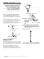
Overflow Line Connection
(not used with filter system)
In the event of a malfunction, the regenerant TANK OVERFLOW
will direct “overflow” to the drain instead of spilling on the
floor. This fitting should be on the side of the cabinet or
regenerant tank. Most tank manufacturers include a post for
the tank overflow connector.
To connect the overflow line, locate hole on side of tank. Insert
overflow fitting into tank and tighten with plastic thumb nut
and gasket as shown (Figure 9). Attach length of 1/2 inch
(1.3 cm) I.D. tubing (not supplied) to fitting and run to drain. Do
not elevate overflow line higher than overflow fitting.
Do not tie into drain line of control unit. Overflow line must be
a direct, separate line from overflow fitting to drain, sewer or
tub. Allow an air gap as per drain line instructions.
Air Gap
Drain
Secure hose in place
Drain Tubing
Overflow Fitting
Figure 9 Overflow Line Connection
Regenerant Line Connection
(not used with filter system)
The regenerant line from the tank connects to the valve. Make
the connections and hand tighten. Be sure that the regenerant
line is secure and free from air leaks. Even a small leak may
cause the regenerant line to drain out, and the conditioner will
not draw regenerant from the tank. This may also introduce air
into the valve causing problems with valve operation.
Most installations utilize a tank check valve. This is not
necessary when using the 255 valve with the built-in aircheck.
Using a tank check valve with the 255 valve with aircheck will
result in premature checking of the aircheck valve, before the
tank is empty.
Regenerant Line Connection
Figure 10 Air Check for 255 valve
Regenerant Line Connection
NOTE: Be sure to
use plumbing
connection tube
when attaching
regenerant line
connections to
the Performa
valve.
Figure 11 Regenerant Connection for Performa Valve
NOTE: When installing a filter (253 or 263 valve) use a cap
on the regenerant line connection to prevent water
seepage from the port. See Parts and Accessories
section for part number.
An aircheck must be used in the regenerant line when
installing a Performa valve.
Figure 12 Regenerant Tank Check Valve (not provided)*
* Furnished as an option from conditioner system manufacturer.
14 •AUTOTROL
®
740/760 Control 255 & Performa Series Valves (268, 268FA) Service Manual

EQUIPMENT INSTALLATION CONTINUED
Electrical Connection
CAUTION
This valve and control are for dry location use only
unless used with a Listed Class 2 power supply
suitable for outdoor use.
All 700 Series controllers operate on 12-volt alternating
current power supply. This requires use of the supplied AC
adapter. A variety of AC adapters are available for different
applications. These AC adapters are available from your
supplier. They include:
AC Adapter Input Voltage Application Part
Number
North American
wall-mount AC
adapter
120V 60Hz Standard indoor
application
1000811
Outdoor rated
AC adapter
120V 60Hz UL listed
for outdoor
installations
1235448
International
option AC
adapters
Varies based
on country
Standard indoor
application
See Parts
Lists Section
100 VAC, 120 VAC and 230 VAC AC Adapters
Make sure power source matches the rating printed on the
AC adapter.
NOTE: The power source should be constant. Be certain
the AC adapter is not on a switched outlet. Power
interruptions longer than 8 hours may cause the
controller to lose the time and day settings. When
power is restored, the day and time settings must
then be re-entered.
The 700 Series controller is available in two power
configurations. The North American controller operates on
60 Hz. If the incoming power is 50 Hz, the "North American"
controller will not function. The error code "ERR 2" will show
on the display.
The "World" controller will sense the input power as 50 or 60
Hz and operate accordingly.
Controller Location
The 700 Series controllers are designed to be mounted on
the valve or attached to a flat surface. Installations that do
not provide easy access to the valve can have the controller
mounted for remote operation.
A remote mount connection, P/N 1256257, is available for the
700 Series controller.
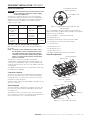
Valve Camshaft
The front end of the camshaft has an indicator cup. The cup
has slots in the outer periphery and numbers on the inside
face (Figure 13).
The numbers can be seen with the cover off, from the front
over the top of the controller. The number at the top indicates
which regeneration cycle is currently in progress.
Treated Water Slot
Treated Water Indicator
(normal operation)
Figure 13 Camshaft Front End for 255, 263, and
268 valve bodies
The corresponding slot for the number is positioned at the
optical sensor which is approximately 90 degrees out of phase.
Regeneration Cycle Indicators
C0 = Treated Water - normal operation mode
C1 = Backwash Cycle
C2 = Regenerant Draw Cycle (not used in filter mode)
C3 = Slow Rinse Cycle (not used in filter mode)
C4 = System Pause
C5 = Fast Rinse Cycle 1
C6 = Backwash Cycle 2
C7 = Fast Rinse Cycle 2
C8 = Regenerant Refill (not used in filter mode)
Valve Disc Operation
1 Regenerant
2 Inlet
3 Outlet
4 Bypass
5 Rinse Drain
6 Backwash/Drain
Figure 14 - 255 Valve
1 Regenerant 3 Inlet
4 Outlet
2 Bypass
6 Rinse Drain
7 Backwash/Drain
5 Refill
Figure 15 - Performa Valve (263, 268)
AUTOTROL
®
740/760 Control 255 & Performa Series Valves (268, 268FA) Service Manual • 15

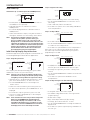
SYSTEM START UP
Initial Power-Up
Initial Power Up – (Camshaft proceeds to HOME position)
Time & Day
Regen
Time & Day
Salt
Capacity
Hardness
SU MO TU WE TH FR SA DAYS
• At initial power-up, the camshaft may need to rotate to
the HOME (in service position).
• Camshaft may take 1 to 2 minutes to return to
HOME position.
• Err 3 will be displayed until the camshaft returns to
HOME position.
• If more than 2 minutes elapses, verify that the motor is
turning the camshaft. If it is not turning, contact Dealer.
NOTE: The 700 Series controller features a self-test
sequence. At first power-up of the control, you
may see a number such as 1.00, 1.02, 1.04, or 2.00
displayed. This is an indication that the self-test is not
completed. To complete the test, verify that the turbine
cable is connected. Blow air into the turbine port (valve
outlet) to spin the turbine. The controller will verify
that the turbine works and the self-test will finish.
Proceed with the initial start-up procedure.
Initial Start Up Step-By-Step Instructions
For FA filter applications, please program as normal below. See
section Programming the 700 for FA Filter Applications.
Step 1: Program System Size
Ffilter
Time & Day
Regen
Time & Day
Salt
SU MO TU WE TH FR SA DAYS
Capacity
Hardness
Time & Day
Regen
Time & Day
Salt
SU MO TU WE TH FR SA DAYS
Capacity
Hardness
This step may have been performed by your system’s OEM
manufacturer. In this case, proceed to step 2.
NOTE: Capacity is the result of the amount of media in the
tank and the salt setting. The default capacity will be
changed by selecting a different regenerant setting.
• Input system size – media volume (For FA filters, choose
your closest media volume) – in cubic feet or liters.
• Use UP and DOWN buttons to scroll through resin
volume choices.
• Choose the nearest volume to your actual system size.
• To choose a filter operation – press DOWN until an “F” is
displayed.
• Press SET to accept the system size you’ve selected.
• If incorrect setting is programmed, see “Resetting the
Control” section below.
NOTE: If the controller was incorrectly set to the wrong valve
body, press the DOWN button and SET button for
five seconds to display resin volume in "HO". Press
and hold the SET button for five seconds to reset the
controller. Use the UP or DOWN buttons to increment
the display to the correct valve body. Press SET.
Step 2: Program Time of Day
Time & Da
y
SU MO TU WE TH FR SA DAYS
Capacity
Hardness
• While “12:00” is blinking, set the correct time of day.
• Use the UP and DOWN buttons to scroll to the correct
time of day.
• “PM” is indicated, “AM” is not indicated.
• Press SET to accept the correct time of day and advance
to the next parameter.
Step 3: Set Day of Week
Time & Day
Regen
Time & Day
Salt
SU MO TU WE TH
FR
SA DA
YS
Capacity
Hardness
• Press SET to make the arrow under “SU” flash.
• Use the UP and DOWN buttons to advance the arrow until
it is under the correct day of week.
• Press SET to accept and advance to the next parameter.
After steps 1-4, the controller will operate most systems.
Proceed to step 4 if further adjustments to your system’s
programming are needed.
Step 4: Set Regen Time
Time & Day
Regen
Time & Day
Salt
SU MO TU WE TH FR SA DAYS
Capacity
Hardness
• 2:00 (AM) is the default time of regeneration. To accept
this time, press the DOWN button to move to step 5.
• To change the regen time, press SET – causing “2:00”
to flash.
• Use the UP and DOWN buttons to advance to the desired
regen time.
• Press SET to accept the time and advance to the
next parameter.
Step 5: Set Days to Regenerate (740 Time-Clock Control Only)
Time & Day
Regen
Time & Day
Salt
SU MO TU WE TH FR SA DAYS
Capacity
Hardness
• If using 760 control – proceed to step 5a.
• Set number of days between time-clock regeneration
(regen frequency).
• Default time is 3 days.
• Days can be adjusted from 1/2 (.5) to 99 days.
• To change, press SET to make the “3” flash.
• Use the UP and DOWN buttons to change the number of
days desired.
• Press SET to accept the regen frequency, and advance to
the next cycle.
16 •AUTOTROL
®
740/760 Control 255 & Performa Series Valves (268, 268FA) Service Manual

Step 5a: Set Calendar Override (760 Demand Control Only)
Time & Day
Regen
Time & Day
Salt
SU MO TU WE TH FR SA DAYS
Capacity
Hardness
• If using 740 control – proceed to step 6.
• Set number of days for calendar override on
demand control.
• “0” days is the default for calendar override.
• Days can be adjusted from 1/2 (.5) to 99 days.
• To change, press SET to make the “0” flash.
• Use the UP and DOWN buttons to change to the number
of days desired. Press SET to accept the regen frequency,
and advance to the next cycle.
Step 6: Amount of Regenerant used per Regeneration
Standard Setting
Time & Day
Regen
Time & Day
Salt Amount
SU MO TU WE TH FR SA DAYS
Capacity
Hardness
Time & Day
Regen
Time & Day
Salt Amount
SU MO TU WE TH FR SA DAYS
Capacity
Hardness
High Capacity Setting
Low Setting(High Efficiency)
Time & Day
Regen
Time & Day
Salt Amount
SU MO TU WE TH FR SA DAYS
Capacity
Hardness
• Set desired regenerant amount.
• Default setting is "S" standard salting.
• 3 salt settings are available on 740 and 760 controls:
• S – Standard Salt – 9 lbs/cubic foot of resin (120 grams/
liter of resin)
• H – High Salt – 15 lbs/cubic foot of resin (200 grams/liter
of resin)
• L – Low Salt – 3 lbs/cubic foot of resin (40 grams/liter
of resin)
• Low Salt is the "Highly Efficient Mode".
• To change salt setting, press the SET button and use the
UP and DOWN buttons to change to the desired setting.
• Press SET to accept the setting and advance to the
next parameter.
• See Dealer Installation Manual for more complete
information on salt settings for different system sizes,
capacities and expected efficiencies.
Filter Backwash Time (Filter Mode Only)
If the system is set up as a filter, the regenerant amount
is unnecessary. The controller deactivates the regenerant
amount setting, and changes to an adjustable backwash time
in minutes.
• Press SET to change the time.
• The default time of 14 minutes will begin to flash.
• Use UP and DOWN to select the appropriate backwash
time for the media type and amount used. The controller
can use 0 to 99 minutes for backwash.
• Press SET again to enter that time.
Step 8: Estimated Capacity
KG
Time & Day
Regen
Time & Day
Salt
SU MO TU WE TH FR SA DAYS
Capacity
Hardness
• System capacity is displayed in total kilograins or kilograms
of hardness removed before a regeneration is necessary.
• Value is derived from the system’s resin volume input and
salt amount input.
• The capacity is displayed for information purposes on the
740 control. It cannot be changed.
• To change capacity on the 760 control, press SET to make
the default capacity flash. Use the UP and DOWN buttons
to increment to the desired capacity.
• Press SET to accept the setting and advance to the
next parameter.
If using the 740 control, programming is complete. The control
will return you to the normal operation mode.
Step 9: Enter Hardness (760 Demand Control Only)
Time & Day
Regen
Time & Day
Backwash Time
SU MO TU WE TH FR SA DAYS
Capacity
Hardness
• Enter inlet water hardness at installation site.
• Default hardness setting is 10 grains (ppm for metric).
• To change hardness, press SET to make the setting flash.
Use the UP and DOWN buttons to scroll to the
desired hardness.
• Press SET to accept the entered hardness value.
• The control will return you to the normal operation mode.
Initial programming is now complete. The control will return to
normal operation mode if a button is not pushed for 30 seconds.
Conditioner and FA Filter Start-Up
After you have performed the previous initial power-up steps, you
will need to place the conditioner into operation.
WARNING:
Do not rotate the camshaft by hand or damage
to the unit may occur. Use the controller to
step the camshaft electronically through
the cycles.
1. Remove the cover from the valve. Removing the cover will
allow you to see that the camshaft is turning, and in which
cycle the camshaft is currently positioned.
2. With the supply water for the system still turned off,
position the bypass valve to the “not in bypass” (normal
operation) position.
3. Hold the REGEN button on the controller down for 5
seconds. This will initiate a manual regeneration.
The controller will indicate that the motor is turning the
camshaft to the cycle C1 (Backwash) position by flashing
an hourglass. The controller will display the total regen
time remaining.
If you press and hold the SET button, the controller will
indicate the time remaining in the current cycle.
SYSTEM START UP CONTINUED
AUTOTROL
®
740/760 Control 255 & Performa Series Valves (268, 268FA) Service Manual • 17

4. Fill the media tank with water.
A. While the controller is in cycle C1 (Backwash), open the
water supply valve very slowly to approximately the 1/4
open position.
WARNING:
If opened too rapidly or too far, media may
be lost out of the tank into the valve or the
plumbing. In the 1/4 open position, you should
hear air slowly escaping from the valve
drain line.
B. When all of the air has been purged from the media
tank (water begins to flow steadily from the drain line),
open the main supply valve all of the way. This will
purge the final air from the tank.
C. Allow water to run to drain until the water runs clear
from the drain line. This purges any refuse from the
media bed.
D. Turn off the water supply and let the system stand for
about five minutes. This will allow any air trapped to
escape from the tank.
5. Add water to the regenerant tank (initial fill)
(conditioner only).
A. With a bucket or hose, add approximately 4 gallons (15
liters) of water to the regenerant tank. If the tank has a
salt platform in the bottom of the tank, add water until
the water level is approximately 1 inch (25 mm) above
the platform.
NOTE: We recommend that you do not put regenerant into
the tank until after the control valve has been put into
operation. With no regenerant in the tank, it is much
easier to view water flow and motion in the tank.
6. Engage the refill cycle to prime the line between the
regenerant tank and the valve (conditioner only).
A. Slowly open the main water supply valve again, to the
fully open position. Be sure not to open too rapidly as
that would push the media out of the media tank.
B. Advance the controller to the Refill (C8) position. From
cycle C1 (Backwash), press and hold the SET button.
This will display the current cycle.
While pressing the SET button, press UP to advance to
the next cycle. Continue to advance through each cycle
until you have reached cycle C8 (Refill).
NOTE: As you advance through each cycle there will be a
slight delay before you can advance to the next cycle.
The hourglass icon will light while the camshaft is
indexing. There may be a pause at cycle C4 (System
Pause). This cycle allows the water/air pressure to
equalize on each side of the valve discs before moving
on. The hourglass will not be visible indicating that
the system is paused.
Time & Day
Regen
Time & Day
Salt
SU MO TU WE TH FR SA DAYS
C
Capacity
Hardness
C. With the water supply completely open, when you arrive
at cycle C8 (Refill), the controller will direct water down
through the line to the regenerant tank. Let the water
flow through the line until all air bubbles have been
purged from the line.
D. Do not let the water flow down the line to the tank for
more than one to two minutes, or the tank may overfill.
E. Once the air is purged from the line, press the SET
button and the UP button simultaneously to advance to
cycle C0 (Treated Water) position.
7. Draw water from the regenerant tank.
A. From the treated water position (cycle C0), advance the
valve to the draw regenerant position. Hold the REGEN
button down for five seconds.
The controller will begin a manual regen, and advance
the control valve to the cycle C1 (Backwash). Press the
SET and UP button to advance to cycle C2 (Draw).
B. With the controller in this position, check to see that
the water in the regenerant tank is being drawn out of
the tank. The water level in the tank should recede
very slowly.
C. Observe the water being drawn from the regenerant
tank for at least three minutes. If the water level does
not recede, or goes up, check all hose connections. C2
should be displayed.
8. If the water level is receding from the regenerant tank
you can then advance the controller back to the treated
water (C0) position by pressing SET and the UP buttons
simultaneously to advance the controller to the C0 position.
9. Finally, turn on a faucet plumbed after the water
conditioner. Run the faucet until the water runs clear. Add
regenerant to the regenerant tank.
Things You Might Need to Know
• When the controller is first plugged in, it may display a
flashing hourglass and the message Err 3, this means
that the controller is rotating to the home position. If
the Err 2 is displayed, check that the incoming power
frequency matches the controller. The North American
controller will not run with 50 Hz input.
• The preset default time of regeneration is 2:00 AM.
• English or Metric? The World controller senses the
electrical input and decides which is needed. The North
American controller only runs on 60 Hz and defaults to
English units.
• The 700 Series controller can be programmed to
regenerate on specific days of the week.
• If electrical power is not available, the camshaft can be
rotated counterclockwise by hand if the motor is removed.
• The 700 Series controllers send commands to the motor
for camshaft movement. However, water pressure/flow
are required during the regeneration cycle for backwash,
purge and refill, and brine draw to actually take place.
• Make sure control power source is plugged in. The
transformer should be connected to a non-switched
power source.
• You can start programming at the beginning by resetting
the amount of media. When viewing H0 (History Value)
push and hold SET for five seconds. The display reverts
back to --- and any programmed information is lost.
Return to Initial Power Up.
SYSTEM START UP CONTINUED
18 •AUTOTROL
®
740/760 Control 255 & Performa Series Valves (268, 268FA) Service Manual

PROGRAMMING
Determining If You Have A 740 Or 760 Control
If you are unsure of your control model, simply remove the
cover and disconnect the controller module from the control
valve. On the back of the control valve is a silver label that will
show your model number and version revision.
Pentair Water USA
Glendale, WI Operations
Model 740
12 V/ 60 Hz/ 4W
VERSION 1.02
WO#4340000
Ser. No: 740090052683-3
®
Serial number with date code
Model number:
either 740, 740C or 760, 760C
Figure 16
General 700 Series Instructions
Power Loss Memory Retention
The 700 Series controllers feature battery-free time and
date retention during the loss of power. This is designed to
last a minimum of 8 hours depending on the installation.
The controller will continue to keep time and day in dynamic
memory while there is no AC power.
The controller will not track water usage on volumetric
demand controls in the event of a power failure.
All programmed parameters are stored in the 700 Series static
memory and will not be lost in the event of a power failure.
These settings are maintained separately from the time and
day settings.
Motor
The 700 series controller uses a standard 12-volt AC motor
that works with either 50 Hz or 60 Hz. The same motor is
used worldwide and does not need to be changed for different
power conditions.
Power
700 Series controllers are available in two power
configurations:
1. The North American model requires 60 Hz input. The
controller will display USA units when power is first applied.
2. The World model accepts either 60 or 50 Hz input and will
automatically adjust measurement units when power is
first applied.
Information entered or calculated by the controller is stored in
two different ways.
A static memory will store:
Media volume
Regenerant setting
Time of regeneration
Days between regeneration
Filter mode
A dynamic memory with 8 hour retention will store:
Current day of week
Running clock
NOTE: Water flow to the valve can be turned on or bypassed
when the controller is powered up for the first time.
Variable Reserve Function
The 700 Series metered-demand volumetric controllers (760
and 760C) are designed to have a variable reserve feature. This
feature automatically adjusts the reserve to the end-user’s
water usage schedule.
A variable reserve saves salt and water by only regenerating
when absolutely necessary, and ensures enough soft water for
typical high-water usage days.
Each day of regeneration the controller reviews the last
four weeks of water usage for the same day of the week to
determine if the remaining capacity is adequate for the next
day of the week. If the remaining capacity is not adequate, it
will initiate an automatic regeneration.
Display Icons 700 Controller
PM
MIN
KGx2
Time & Day
Regen Time & Day
Salt
SU MO TU WE TH FR SA DAYS
x100P
HC
Capacity
Hardness
1
10
8
9
7
6
5
4
3
2
11
18
19
17
16
15
14
13
12
20
21
23
22
25
24
Figure 17
NOTE: In normal operation and during programming, only a
few of the icons will actually be displayed.
1. Days of the week. The flag immediately below the day will
appear when that day has been programmed as a day the
system should regenerate (used with 7-day
timer programming).
2. See #3
3. This cursor is displayed when the days between
regeneration are being programmed (used with .5 to 99 day
regeneration programming).
4. One of these cursors will be displayed to indicate which day
will be programmed into the controller.
5. "PM" indicates that the time displayed is between 12:00
noon and 12:00 midnight (there is no AM indicator). PM
indicator is not used if clock mode is set to 24-hour.
6. When "MIN" is displayed, the value entered is in
minute increments.
7. When "Kg" is displayed, the value entered is in kilograms
or kilograins.
8. Four digits used to display the time or program value. Also
used for error codes.
9. Colon flashes as part of the time display. Indicates
normal operation.
10. Locked/unlocked indicator. In Level I programming this
is displayed when the current parameter is locked-out.
It is also used in Level II programming to indicate if the
displayed parameter will be locked (icon will flash) when
controller is in Level I.
AUTOTROL
®
740/760 Control 255 & Performa Series Valves (268, 268FA) Service Manual • 19

11. When "x2" is displayed, a second regeneration has been
called for.
12. The recycle sign is displayed (flashing) when a regeneration
at the next time of regeneration has been called for. Also
displayed (continuous) when in regeneration.
13. The display cursor is next to "SALT" when programming
the amount of regenerant. If the controller is on a filter
then backwash time is programmed.
14. The display cursor is next to "REGEN TIME & DAY" when
programming the time of regeneration and the days
of regeneration.
15. The display cursor is next to "TIME & DAY" when
programming the current time and day.
16. The hourglass is displayed when the motor is running. The
camshaft should be turning.
17. These cursors will appear next to the item that is
currently displayed.
18. X100 multiplier for large values.
19. Shows when water is flowing through the valve.
20. Used with #24, #25, and #26. Displays a sequence number
or a value.
21. History Values (H). The number displayed by #23 identifies
which history value is currently displayed.
22. Parameter (P). Displayed only in Level II Programming.
The number displayed by #23 identifies which parameter is
currently displayed.
23. Cycle (C). The number displayed by #23 is the current cycle
in the regeneration sequence.
24. Hardness setting—only used with 760 and 760C controllers.
25. Capacity display—shows estimated system capacity.
Keypad — Buttons
1
4
3
2
1. DOWN arrow. Generally used to scroll down or increment
through a group of choices.
2. SET. Used to accept a setting that normally becomes stored
in memory. Also used together with the arrow buttons.
3. UP arrow. Generally used to scroll up or increment through
a group of choices.
4. Regenerate. Used to command the controller to
regenerate. Also used to change the lock mode.
NOTE: If a button is not pushed for thirty seconds, the
controller returns to normal operation mode.
Pushing the regenerate button immediately returns
the controller to normal operation.
Programming Conventions
The 700 Series controller is programmed using the buttons on
the keypad. The programming instructions will be described
two ways whenever a section has keypad input.
First, a table shows simplified instructions. Second, text
follows that describes the action. In each table:
"Action" lists the event or action desired.
"Keys" are listed as:
UP for up arrow
DOWN for down arrow
SET for set
REGEN for regeneration
"Duration" describes how long a button is held down:
P/R for press and release
HOLD for press and hold
X sec for a number of seconds to press the button and
hold it down
"Display" calls out the display icons that are visible.
Regeneration Modes
The 700 Series controllers can be regenerated either
automatically or manually. During a regeneration, the total time
remaining of the regeneration will be displayed on the controller.
The current cycle is shown in the lower left of the display.
To Initiate a Manual Regeneration:
• Press REGEN once for delayed regeneration. System will
regenerate at next set regen time (2:00 AM). A flashing
regen (recycle) symbol will be displayed.
• Press and hold REGEN for 5 seconds to initiate
immediate manual regeneration. A solid regen symbol
will be displayed.
• After immediate regeneration has begun, press REGEN
again to initiate a second manual regeneration. A flashing
"x2" symbol indicates the second regeneration will start
at the time of regeneration. Press and hold REGEN to
turn on the second regeneration immediately following
the current regeneration. The double regeneration is
indicated by the "x2" symbol being on steady.
During a Regeneration:
Total regen
time remaining
Time & Day
Regen
Time & Day
Salt
SU MO TU WE TH FR SA DAYS
C
Capacity
Hardness
MIN
x2
• A "C#" is displayed to show current cycle.
• Total regen time remaining is displayed on screen.
• Press and hold SET to show current cycle time remaining.
PROGRAMMING CONTINUED
20 •AUTOTROL
®
740/760 Control 255 & Performa Series Valves (268, 268FA) Service Manual
Page is loading ...
Page is loading ...
Page is loading ...
Page is loading ...
Page is loading ...
Page is loading ...
Page is loading ...
Page is loading ...
Page is loading ...
Page is loading ...
Page is loading ...
Page is loading ...
Page is loading ...
Page is loading ...
Page is loading ...
Page is loading ...
Page is loading ...
Page is loading ...
Page is loading ...
Page is loading ...
Page is loading ...
Page is loading ...
Page is loading ...
Page is loading ...
Page is loading ...
Page is loading ...
Page is loading ...
Page is loading ...
-
 1
1
-
 2
2
-
 3
3
-
 4
4
-
 5
5
-
 6
6
-
 7
7
-
 8
8
-
 9
9
-
 10
10
-
 11
11
-
 12
12
-
 13
13
-
 14
14
-
 15
15
-
 16
16
-
 17
17
-
 18
18
-
 19
19
-
 20
20
-
 21
21
-
 22
22
-
 23
23
-
 24
24
-
 25
25
-
 26
26
-
 27
27
-
 28
28
-
 29
29
-
 30
30
-
 31
31
-
 32
32
-
 33
33
-
 34
34
-
 35
35
-
 36
36
-
 37
37
-
 38
38
-
 39
39
-
 40
40
-
 41
41
-
 42
42
-
 43
43
-
 44
44
-
 45
45
-
 46
46
-
 47
47
-
 48
48


Autotrol AUTOTROL 760 CONTROL 255 Owner's manual
- Type
- Owner's manual
- This manual is also suitable for
Ask a question and I''ll find the answer in the document
Finding information in a document is now easier with AI
Related papers
-
Autotrol 742/762 Control 255 & Performa (263, 268, 268 FA) Owner's manual
-
Autotrol Logix 764 Control Performa CV Series Owner's manual
-
Autotrol Performa FA Valve Owner's manual
-
-
-
-
-
-
-
Other documents
-
 Water Right Sanitizer Plus ASP2-1044 Installation Instructions & Owner's Manual
-
 Tahoe T../MA-BTB series Installer Manual
-
Pentair Whole House Softening Owner's manual
-
Hellenbrand H200M-450 Owner's manual
-
-
 US Water Systems Flex ECS-34 Operating instructions
-
-
GE AvantaPure Professional 269 Operating instructions
-
-
 Excalibur Water Systems CHLOROSOFT SERIES Installation guide


