
727

727
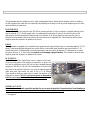
INSTALLATION
This glasswasher must be installed on a level, rigid, nonflammable surface. Ensure that the machine is level by installing
the feet (shipped in the wash tank of the machine) and adjusting the leveling. Be sure to provide adequate space for water,
drain and electrical connections.
WATERSUPPLY
A 1/2" - HOT (60°C) hot water line with 30 PSI flow pressure and shut-off valve is required. A pressure reducing valve*
may be required. A 1/2" flexible supply hose* is recommended from the shut-off valve to the water fill valve on the
dishwasher to facilitate maintenance and servicing of the machine. A 90° elbow adapter for the water inlet valve is
furnished with the machine and can be found in the wash tank with the adjustable feet. There should be sufficient hose
length to permit the machine to be pulled out for service.
DRAIN
This glasswasher is equipped with an automatic drain pump that will pump the drain water to a maximum height of 36" (0.9
meter). Drain pump equipped machines have a white button on the control panel beside the green power button. 1" ID
flexible drain hose* is recommended to facilitate maintenance and servicing of the machine. It is important not to reduce
the size of this hose. A 1" check-valve* is required on drain pump equipped models. There should be sufficient hose
length to permit the machine to be pulled out for service.
ELECTRICAL
A 208-240 volt, 60 Hz, Single Phase circuit is required for this unit.
Check the rating plate on the machine for amp draw. In spite of the
fact that the rating plate shows 208 volts, the unit is designed function
properly on 208 volts to 240 volts. The terminal block is located at the
back, base of the machine. Open the cover, pass the cable through the
cable strain relief and connect the wires to the LI, L2 & Ground.
There should be sufficient cable length to permit the machine to be
pulled out for service. DO NOT turn on the power to the machine
until the water supply & drain lines have been connected.
IMPORTANT NOTE
Reasonable access to and around the machine for service must be provided. Disconnecting of hard plumbing or
removal of counter tops or cabinets, etc.. for servicing is not covered by warranty.
* - not supplied

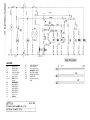
LEGEND
F
AUDIO FILTER
TV
TANK THERMOSTAT
MPS DRAIN PUMP RV TANK ELEMENT
TL POWER SWITCH LP
PILOT LIGHT READY
MACHINE
PS PRESSOSTAT LL PILOT LIGHT POWER
ELB SOLENOID VALVE
RB BOOSTER ELEMENT
TC CYCLE SWITCH DPS DRAIN PUMP SWITCH
BR
MICRO RELAY
COIL
MPS DRAIN PUMP
CR 1-2 MICRO RELAY MPD
MOTOR DETERGENT
PUMP
T
DIGITAL
THERMOMETER
MPL WASH PUMP
MP DOOR SWITCH
MT TIMER MOTOR
Ml MICRO SWITCH
M2 MICRO SWITCH
M3 MICRO SWITCH
LC
PILOT
LIGHT
CYCLE
TB
BOOSTER
THERMOSTAT


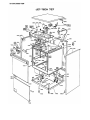
727 PARTS LIST
10349 CONNECTOR 12072 NUT
10415 NUT 12073 PLUG
10421 SMALL SQUARE 12076 MANIFOLD
10425 NUT 12077 HANDLE SOCKET
10435 NUT 12127 TUBE
10446 RINSE AID FILTER 12131 RUBBER-CARRIER
10458 NUT 12169 WASH/RINSE ARM
10470 SPRING 12170 RIGHT RINSE ARM
10471 SPRING 12171 LEFT RINSE ARM
10472 SPRING 12174 WASH ARM
10473 SPRING 12184 HANDLE
10475 SPRING 12192 SQUARE
10479 BUFFER 12194 SQUARE
10489 PIVOT 12435 FILM 727 DP JET-TECH
10493 PIVOT 15006 PIVOT
10502 ADJUSTABLE FOOT 15026 CONNECTOR DIAMETER 7,5
10523 HANDLE SOCKET 15030 KIT SUPERIOR SUPPORT ARM
10528 AIR TRAP 15031 KIT INFERIOR SUPPORT ARM
10529 TUBE 15501 WASH TANK
10552 PLATE 15502 BASE
10556 FAIR LEAD 15503 DOOR
10565 HANDLE SOCKET 15504 RIGHT SIDE
10569 DISK 15505 LEFTSIDE
10576 NUT + RUBBER -- CARRIER SOLENOID V. 15509 RIGHT BASKET GUIDE
10598 SQUARE 15510 LEFT BASKET GUIDE
10609 SPACER 15511 GUIDE
11351 BUSHING 15512 GUIDE
12007 SUPPORT 15513 FILTER
12008 SUPPORT 15514 FILTER
12009 HUB 15515 BOOSTER TANK
12010 PLUG 15646 PANEL JET-TECH 727
12013 PLUG 15507 TOP
12014 RINSE JET 15506 PANEL
12015 RINSE JET INSERT 15705 SQUARE MICROSWITCH
12017 PIVOT 15720 COLLAR FOR DRAIN PLUG
12019 PLATE 15918 PAN EL DIGITAL MEASURE ME NT
12020 NUT 20010 LENS
12021 CONNECTOR 20018 FILTER
12022 LID WITH FILTER 20042 LIGHT
12024 CONNECTOR 20045 TERMINAL BLOCK
12025 TUBE 20067 RELAY 12A 230V
12027 CONNECTOR 20069 BOOSTER HEATING ELEM. 230V 2400W
12028 NUT 20119 RINSE THERMOSTAT
12029 DISK 20130 TERMINAL
12030 TUBE 20131 TERMINAL PART
12035 TUBE 20190 FIXING CABLE
12036 TUBE 20192 PRESSURE SWITCH
12037 TUBE 20199 RINSE AID PUMP
12048 PIVOT 20500 POWER SWITCH DP
12049 DOOR HOOK 20504 WASH TANK ELEMENT 230V 2000W
12050 DOOR CATCH 20514 DIGITAL TEMP. DISPLAY
12051 BUSH 20518 TIMER 60Hz
12052 SPRING 20519 CYCLE START SWITCH
12054 DOOR CATCH BODY 20548 DOOR MICROSWITCH UL F 18
12055 SCREW 20566 CAPACITOR 12,5MF 240UL
12057 HANDLE SOCKET 20568 SOLENOID VALVE 2A 240V 60HZ
12060 ANTI-VIBRATION 20570 WASH THERMOSTAT

727
PARTS LIST
21444 WIRING HARNESS 727 DP 60234 WASHER
30012 GLASS BASKET 16x16x5 60235 WASHER
30035 SAUCER INSERT 60242 WASHER
30026 CUTLERY HOLDER 2 COMP. 60244 WASHER
30116 GLASS BASKET 4 COMP. 16x16 60245 WASHER
40028 MOTOR PUMP 60258 BALL
40249 DRAIN PUMP 60Hz 60555 HOSE
60003 GASKET 60563 HOSE
60004 GASKET 15x10x2 60565 HOSE
60008 GASKET
60009 GASKET
60012 GASKET
60017 GASKET
60018 GASKET
60050 O RING
60060 O RING
60061 O RING
60071 O RING
60072 O RING
60073 O RING
60074 O RING
60075 O RING
60076 O RING
60078 CLAMP
60079 CLAMP
60081 CLIP
60083 CLIP
60084 CLIP
60089 CLIP
60102 SCREW
60103 SCREW
60107 SCREW
-
 1
1
-
 2
2
-
 3
3
-
 4
4
-
 5
5
-
 6
6
-
 7
7


Ask a question and I''ll find the answer in the document
Finding information in a document is now easier with AI
Related papers
Other documents
-
Champion TUW-15 User manual
-
 Washtech XP User manual
-
Champion EEUCCW-8 Operating instructions
-
Champion DHB Owner's manual
-
Moyer Diebel 351HT User manual
-
-
 Washtech XP User manual
-
-
-

