COMFORT-AIRE A-VMH28TU-1 Owner's manual

Type
Owner's manual
www.marsdelivers.com
Service Manual
VMH Series
Inverter Multi Zone Ductless Mini-Split
A-VMH18DU-1
A-VMH28TU-1
A-VMH36QU-1
A-VMH48PU-1
www.marsdelivers.com
Service Manual - VMH 18/28/36/48 Series
3
CONTENTS
1. Indoor Unit Combination .......................................................................................................................................... 4
2. Dimensions Of Outdoor Unit...................................................................................................................................... 6
3. Refrigerant Cycle Diagram ........................................................................................................................................ 8
4. Installation Details .................................................................................................................................................. 10
4.1 Wrench torque sheet for installation ............................................................................................................... 10
4.2 Connecting the cables ...................................................................................................................................... 10
4.3 Pipe length and elevation ................................................................................................................................. 10
4.4 First-Time Installation ....................................................................................................................................... 10
4.5 Adding Refrigerant after Long-Term System Operation................................................................................... 12
4.6 Procedure when servicing the indoor unit refrigeration circuit. ...................................................................... 12
4.7 Evacuation after servicing the outdoor unit refrigeration circuit .................................................................... 13
5. Electronic Function ................................................................................................................................................. 15
5.1 Abbreviation ..................................................................................................................................................... 15
5.2 Electric Control Working Environment. ............................................................................................................ 15
5.3 Main Protection ................................................................................................................................................ 15
5.4 Control and Functions ...................................................................................................................................... 17
6. Wiring Diagrams ..................................................................................................................................................... 22
7. Troubleshooting ..................................................................................................................................................... 28
7.1 Safety ................................................................................................................................................................ 28
7.2 Indoor Unit Error Display.................................................................................................................................. 29
7.3 Outdoor Unit Display ........................................................................................................................................ 32
7.4 Diagnosis and Solution ..................................................................................................................................... 37
7.5 Trouble Criterion of Main Parts. ....................................................................................................................... 86
8. Disassembly Instructions ........................................................................................................................................ 97
A-VMH18DU-1 ............................................................................................................................................... 97
A-VMH28TU-1................................................................................................................................................ 97
Service Manual - VMH 18/28/36/48 Series
4
A-VMH36QU-1........................................................................................................................................................ 105
A-VMH48PU-1........................................................................................................................................................ 112
Service Manual - VMH 18/28/36/48 Series
5
1. Indoor Unit Combination
Multi DC
Outdoor Unit
Nominal
capacity
Suggested
Combination
Limit
2 Zone
5.2kW
12
None
9+9
9+12
12+12
Multi DC
Outdoor Unit
Nominal
capacity
Suggested
Combination
Limit
3 Zone 7.8kW
9+9
None
9+12
9+18
12+12
12+18
18+18
9+9+9
9+9+12
9+9+18
9+12+12
9+12+18
12+12+12
Multi DC
Outdoor Unit
Nominal
capacity
Suggested
Combination
Limit
4 Zone 10.5kW
9+18
None
12+12
12+18
18+18
9+9+9
9+9+12
9+9+18
9+12+12
9+12+18
9+18+18
12+12+12
12+12+18
12+18+18
9+9+9+9
9+9+9+12
9+9+9+18
9+9+12+12
9+9+12+18
9+12+12+12
12+12+12+12
Service Manual - VMH 18/28/36/48 Series
6
Service Manual - VMH 18/28/36/48 Series
7
2. Dimension Of Outdoor Unit
H
D
A
B
Model
Unit
W D H W1 A B
A-VMH18DU-1
mm
946 410 810 1034 673 403
inch
37.2
16.5
31.9
40.6
26.5
15.9
A-VMH28TU-1
mm
946 410 810 1034 673 403
inch
37.2
16.5
31.9
40.6
26.5
15.9
Service Manual - VMH 18/28/36/48 Series
8
H
W
A
D
W1
B
Model
Unit
W
D
H
W1
A
B
A-VMH36QU-1
mm
952
415
1333
1060
634
404
inch
37.5
16.3
52.5
41.7
25.0
15.9
Service Manual - VMH 18/28/36/48 Series
9
3. Refrigerant Cycle Diagram
3.1 Refrigeration circuit drawing of inverter 1 drive 2 type
LIQUID VALVE A
GAS VALVE A
HEAT
EXCHANGE
(EVAPORATOR)
HEAT
EXCHANGE
(CONDENSER)
Compressor
4-WAY VALVE
COOLING
HEATING
T2 Evaporator
temp. sensor
middle
T1 Room
temp. sensor
T3
Condenser
temp. sensor
T5 Discharge
temp. sensor
T4 Ambient
temp. sensor
INDOOR OUTDOOR
EXV A
CAPILLARY A
CHECK VALVE
CAPILLARY TUBE
EXV B
CAPILLARY B
LIQUID VALVE B
GAS VALVE B
Accumulator
T2B-A Evaporator
temp. sensor outlet
T2B-B
3.2 Refrigeration circuit drawing of inverter 1 drive 3 type
LIQUID VALVE A
GAS VALVE A
HEAT
EXCHANGE
(EVAPORATOR)
HEAT
EXCHANGE
(CONDENSER)
Compressor
4-WAY VALVE
COOLING
HEATING
T2 Evaporator
temp. sensor
middle
T1 Room
temp. sensor
T3
Condenser
temp. sensor
T5 Discharge
temp. sensor
T4 Ambient
temp. sensor
INDOOR OUTDOOR
EXV A
CAPILLARY A
CHECK VALVE
CAPILLARY TUBE
EXV B
CAPILLARY B
LIQUID VALVE B
GAS VALVE B
EXV C
CAPILLARY C
LIQUID VALVE C
GAS VALVE C
Accumulator
T2B-A Evaporator
temp. sensor outlet
T2B-B
T2B-C
Service Manual - VMH 18/28/36/48 Series
10
3.3 Refrigeration circuit drawing of inverter 1 drive 4 type
LIQUID VALVE A
GAS VALVE A
HEAT
EXCHANGE
(EVAPORATOR)
HEAT
EXCHANGE
(CONDENSER)
Compressor
4-WAY VALVE
COOLING
HEATING
T2 Evaporator
temp. sensor
middle
T1 Room
temp. sensor
T3
Condenser
temp. sensor
T5 Discharge
temp. sensor
T4 Ambient
temp. sensor
INDOOR OUTDOOR
EXV A
CAPILLARY A
CHECK VALVE
CAPILLARY TUBE
EXV B
CAPILLARY B
LIQUID VALVE B
GAS VALVE B
EXV C
CAPILLARY C
LIQUID VALVE C
GAS VALVE C
EXV D
CAPILLARY D
LIQUID VALVE D
GAS VALVE D
Accumulator
High pressure
switch
Low pressure
switch
T2B-A
Evaporator
temp. sensor outlet
T2B-B
T2B-C
T2B-D
Service Manual - VMH 18/28/36/48 Series
11
4. Installation Details
4.1 Wrench torque sheet for installation
Outside diameter Torque Additional tightening torque
mm inch N.cm N.cm
Ф6.35 1/4 1500(153kgf.cm) 1600(163kgf.cm)
Ф9.52 3/8 2500(255kgf.cm) 2600(265kgf.cm)
Ф12.7 1/2 3500(357kgf.cm) 3600(367kgf.cm)
4.2 Connecting the cables
The power cord connection should be
selected according to the following
specifications sheet.
Unit
AWG
1 drive 2 type (18K outdoor unit). 14
1 drive 3 type (28K outdoor unit) 12
1 drive 4 type (36K outdoor unit) 10
For indoor unit and outdoor unit connection
line, use 14AWG.
4.3 Pipe length and elevation
Maximum piping length and height difference
1 drive 2
1 drive 3
1 drive 4
Max. length for all
rooms (m)
40
(131ft)
60
(197ft)
80
(262ft)
Max. length for
one IU (m)
25 (82ft) 30 (98ft)
35
(115ft)
Max. height
difference between
IU and OU (m)
15
(49.2ft)
15
(49.2ft)
15
(49.2ft)
Max. height
difference between
IUs (m)
10 (33ft) 10 (33ft) 10 (33ft)
Additional refrigerant charge
1 drive 2
1 drive 3
1 drive 4
Pre-charge pipe
length (m)
15
(49.2ft)
22.5
(73.8ft)
30
(98.4ft)
Additiona
l
refrigeran
t charge
g
15 x
(length
for all
rooms -
15)
15 x
(length
for all
rooms
22.5)
15 x
(length
for all
rooms -
30)
oz
0.161
x(length
for all
rooms
49.2)
(0.161
x(length
for all
rooms
73.8)
0.161x(le
ngth for
all rooms
98.4)
Caution:
Refrigerant pipe diameter is different
according to indoor unit to be connected.
When using the extension pipe, refer to the
tables below.
When refrigerant pipe diameter is different
from that of the outdoor unit connector (18K
indoor unit) an additional adapter is required.
Indoor unit
Extension pipe diameter
(mm/inch)
Model
Pipe diameter
(mm/inch)
9K
Liquid
6.35(1/4)
Liquid
6.35(1/4)
Gas
9.52(3/8)
Gas
9.52(3/8)
12K 18K
Liquid
6.35(1/4)
Liquid
6.35(1/4)
Gas
12.7(1/2)
Gas
12.7(1/2)
24K
Liquid
9.52 (3/8)
Liquid
9.52 (3/8)
Gas
15.9(5/8)
Gas
15.9(5/8)
Outdoor unit union diameter (mm/inch)
1 drive 2
Liquid
6.35(1/4) *2
Gas
9.52(3/8) *2
1 drive 3
Liquid
6.35(1/4) *3
Gas
9.52(3/8) *2
12.7(1/2) *1
1 drive 4
Liquid
6.35(1/4) *4
Gas
9.52(3/8) *2
12.7(1/2) *2
4.4 First-Time Installation
Air and moisture in the refrigerant system cause
the following problems:
Increases in system pressure
Increases in operating current
Decreases in cooling and heating efficiency
Blocks in capillary tubing caused by moisture
in the refrigerant circuit freezing
Corrosion of parts in the refrigerant system
caused by water
The indoor units and the pipes between
indoor and outdoor units must be tested for
leakages and evacuated to remove gas and
moisture from the system.
Gas leak check with soap water:
Apply soap water or a liquid neutral
detergent on the connections with a soft brush to
check for leakage in the pipe connecting points. If
bubbles emerge, the pipes are leaking.
1. Air Purging Using the Vacuum Pump
Service Manual - VMH 18/28/36/48 Series
12
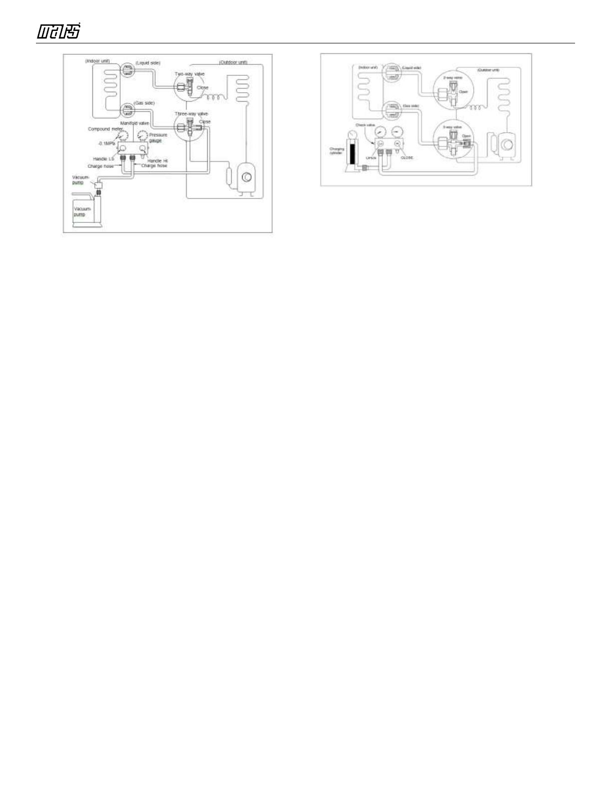
1. Completely tighten the flare nuts on the
indoor and outdoor units. Confirm that both
the2-way and 3-way valves are set to the
closed position.
2. Connect the charge hose with the push pin of
the Handle Lo to the 3-way valve gas service
port.
3. Connect the charge hose of the Handle Hi to
the vacuum pump.
4. Fully open the Handle Lo of the manifold
valve.
5. Turn on the vacuum pump to begin
evacuation.
6. Conduct a 30-minute evacuation. Check
whether the micron gauge indicates 250
microns. If the meter does not indicate
250 microns after 30 minutes has elapsed,
continue evacuation for 20 more minutes. If
the pressure does not reach 250 microns
after 50 minutes has elapsed, check if
there are any leaks.
Fully close the Handle Lo valve of the manifold
valve and turn off the vacuum pump. After 5
minutes, confirm the micron gauge is below
500 microns. Remove micron gauge to avoid
damage.
7. Turn the flare nut on the 3-way valve 45°
counterclockwise for 6-7 seconds. Once gas
begins to come out, tighten the flare nut.
Make sure the pressure display on the
pressure indicator is higher than atmospheric
pressure. Then remove the charge hose from
the 3-way valve.
8. Fully open the 2-wayand 3-way valves and
securely tighten the cap on the 3-way valve.
2. Adding refrigerant if the pipe length
exceeds chargeless pipe length
Procedure:
1)
Connect the charge hose to the charging cylinder
and open the 2-way and 3-way valves.
With the charge hose you disconnected from the
vacuum pump, connect it to the valve at the
bottom of the cylinder.
If the refrigerant is R410A, place the cylinder
bottom-up to ensure liquid charging is possible.
2). Purge the air from the charge hose.
Open the valve at the bottom of the cylinder and
press the check valve on the charge set (be
careful of the liquid refrigerant).
3) Place the charging cylinder onto the electronic
scale and record the weight.
4) Turn on the air conditioner in cooling mode.
5) Open the valves (Low side) on the charge set.
Charge the system with liquid refrigerant.
6).When the electronic scale displays the proper
weight (refer to the table), disconnect the charge
hose from the 3-way valve’s service port
immediately and turn off the air conditioner before
disconnecting the hose.
7). Mount the valve stem caps and the service port
Use a torque wrench to tighten the service port
cap to a torque of 18N.m(13.27 ft·lbs).
Be sure to check for gas leaks.
Service Manual - VMH 18/28/36/48 Series
13
4.5 Adding Refrigerant after Long-Term
System Operation
Procedure
1) If it is suspected that the unit refrigerant is
incorrect, it will be necessary to remove all
refrigerant using a refrigerant recovery
machine, evacuate, and recharge the system.
Please refer to the first time installation
instructions starting on page 17, recovering the
entire indoor and outdoor system.
2) Remember to charge the system with the
factory charge listed on the outdoor unit
nameplate, plus any additional refrigerant
required for additional line length.
Be sure to check for refrigerant leaks.
4.6 Procedure when servicing the indoor
unit refrigeration circuit.
1. Collecting the refrigerant into the outdoor
unit
Procedure
1). Confirm that both the 2-way and 3-way
valves are set to the opened position
Remove the valve stem caps and confirm that
the valve stems are in the opened position.
Be sure to use a hexagonal wrench to operate
the valve stems.
2). Connect the charge hose with the push pin
of handle lo to the 3-way valves gas service port.
3). Air purging of the charge hose.
Open the handle Lo valve of the manifold
valve slightly to purge air from the charge hose
for 5 seconds and then close it quickly.
4). Set the 2-way valve to the close position.
5). Operate the air conditioner at the cooling
cycle and stop it when the gauge indicates 0.1MPa.
6). Set the 3-way valve to the closed
position immediately
Do this quickly so that the gauge ends up
indicating 0.3 to 0.5Mpa.
Disconnect the charge set, and tighten the 2-
way and 3-way valve’s stem nuts.
Use a torque wrench to tighten the 3-way
valves service port cap to a torque of 18N.m.
Be sure to check for gas leakage.
2. Air purging with vacuum pump
Service Manual - VMH 18/28/36/48 Series
14
1) Completely tighten the flare nuts of the indoor
and outdoor units, confirm that both the 2-way
and 3-way valves are set to the closed
position.
2) Connect the charge hose with the push pin of
handle lo to the 3-way valves gas service
port.
3) Connect the charge hose of handle hi
connection to the vacuum pump.
4) Fully open the handle Lo of the manifold valve.
5) Operate the vacuum pump to evacuate.
6) Evacuate for 30 minutes and check whether
the micron gauge indicates 250 microns.
If the meter does not indicate 250
microns after pumping 30 minutes, it should
be pumped 20 minutes more. If the pressure
can’t achieve 250 microns after pumping
50 minutes, please check for leakage
points.
Fully close the handle Lo valve of the manifold
valve and stop the operation of the vacuum
pump. Confirm that the gauge needle does not
move
(approximately 5 minutes after turning off the
vacuum pump).
7) Turn the flare nut of the 3-way valves about
8) Fully open the 2 way valve and 3 way valve
valve.
4.7 Evacuation after servicing the outdoor
unit refrigeration circuit
1. Evacuation of the complete refrigeration
circuit, Indoor and outdoor unit.
Procedure:
1). Confirm that both the 2-way and 3-way valves
are set to the opened position.
2). Connect the vacuum pump to 3-way valve’s
service port.
3). Evacuate for approximately one hour.
Confirm that the micron gauge indicates 250
microns.
4). Close the valve (Low side) on the charge set,
turn off the vacuum pump, and confirm that the
gauge needle does not move (approximately 5
minutes after turning off the vacuum pump).
5). Disconnect the charge hose from the vacuum
pump.
2. Refrigerant charging
Procedure:
1). Connect the charge hose to the charging
cylinder, open the 2-way valve and the 3-way
valve.
Connect the charge hose which you disconnected
45° counterclockwise for 6 or 7seconds after
the gas comes out, then tighten the flare nut
again. Make sure the pressure display in the
pressure indicator is a little higher than the
atmosphere pressure. Then remove the
charge hose from the 3 way valve.
and securely tighten the cap of the 3 way valve
Service Manual - VMH 18/28/36/48 Series
15
from the vacuum pump to the valve at the bottom
of the cylinder. If the refrigerant is R410A, make
the cylinder bottom up to ensure liquid charge.
2). Purge the air from the charge hose
Open the valve at the bottom of the cylinder and
press the check valve on the charge set to purge
the air (be careful of the liquid refrigerant).
3) Put the charging cylinder onto the electronic
scale and record the weight.
4). Open the valves (Low side) on the charge set
and charge the system with liquid refrigerant
If the system cannot be charge with the specified
amount of refrigerant, or can be charged with a
little at a time (approximately 5 oz. each time) ,
operating the air conditioner in the cooling cycle;
if one time is not sufficient, wait
approximately 1 minute and then repeat the
procedure.
5).When the electronic scale displays the proper
weight, disconnect the charge hose from the 3-
way valves service port immediately
If the system has been charged with liquid
refrigerant while operating the air conditioner, turn
off the air conditioner before disconnecting the
hose.
6). Mount the valve stem caps and the service
port. Use torque wrench to tighten the service
port cap to a torque of 18N·m (13.27 ft·lbs).
Always leak check after servicing the refrigerant
system.
For A-VMH18DU-1, A-VMH28TU-1, A-
VMH36QU-1
There are one low-pressure centralized valve and
one high-pressure centralized valve, refer to
the previous instructions for evacuation and
refrigerant recovery.
Service Manual - VMH 18/28/36/48 Series
16
5. Electronic Function
5.1 Abbreviation
T1: Indoor ambient temperature
T2: Middle indoor heat exchanger coil
temperature
T2B: Indoor heat exchanger exhaust coil
temperature (located on the outdoor unit)
T3: Outdoor heat exchanger pipe temperature
T4: Outdoor ambient temperature
T5: Compressor discharge temperature
5.2 Electric Control Working Environment.
5.2.1 Input voltage: 230V.
5.2.2 Input power frequency: 60Hz.
5.2.3 Indoor fan standard working amp.: <1A
5.2.4 Outdoor fan standard working amp.: <1.5A.
5.2.5 Four-way valve standard amp.: <1A.
5.3 Main Protection
5.3.1 Compressor Restart Delay
---- The compressor takes 1 minute to start up the
first time. Further restarts take 3 minutes.
5.3.2 Temperature Protection of Compressor
Discharge.
When the discharge temperature of the
compressor rises, the running frequency is limited
according to the following rules:
----If 105 (221 ℉� ) ≦� T5<110 (230 ℉� ),
maintain the current frequency.
----If the temperature increases and T5 110
(230 ), the frequency decreases to a lower
level every 2 minutes till to F1.
---If T5 115 (239 ) for 10 seconds, the
compressor stops and then restart, when
T5<90 (194 ).
5.3.3 Fan Speed Malfunction
---- If outdoor fan speed is lower than 100RPM or
higher than 2400RPM for 60 seconds or more,
the unit stops and LED displays
E8 failure code.
5.3.4 Inverter Module Protection.
---- The inverter protection module ensures that
faults related to current, voltage, or
temperature do not damage the inverter.
If these protections are triggered, the A/C unit
stops and the LED displays the failure code.
The unit restarts3minutes after the protection
mechanism has turned off.
5.3.5 Low Voltage Protection
VOLTAGE
No limit
VOLT_LTM_FREQ1_ADD
VOLT_LTM_FREQ2_ADD
Note: If low voltage protection triggers and
voltage is not restored to normal within 3
minutes, the protection remains active even
after a machine restart.
5.3.6 Compressor Current Limit Protection
The temperature interval for the current limit is
the same as the range of the T4 frequency limit.
Cooling mode:
Service Manual - VMH 18/28/36/48 Series
17
CoolReturnI
The difference between current limit
and shutdown current
CoolT4Zone5I
Cooling T4122°F current limit value
CoolT4Zone4I
Cooling 49T4113°F current
limit value
CoolT4Zone3I
Cooling 44T4106°F current
limit value
CoolT4Zone2I
Cooling 40T491°F current
limit value
CoolT4Zone1I
Cooling 32T4°F current limit value
CoolStopI
Cooling stop protection current value
Heating mode:
15
14 HeatT4Zone4I
10
9 HeatT4Zone3I
6
5 HeatT4Zone2I
HeatT4Zone1I
HeatReturnI
The difference between current limit
and shutdown current
HeatT4Zone4I
Heating T459°F current
limit value
HeatT4Zone3I
Heating 14T450°F
current limit value
HeatT4Zone2I
Heating 9T443°F current
limit value
HeatT4Zone1I
Heating
5
T4
current limit value
HeatStopI
Heating stop protection current
value
5.3.7 Indoor / Outdoor Units Communication
Protection
If the indoor units do not receive the feedback
signal from the outdoor units for 2 consecutive
minutes, the unit stops. The unit displays the
failure code.
5.3.8 High Condenser Coil Temp. Protection
5.3.9 Outdoor Unit Anti-Freezing Protection
When T2<39.2°F for 250seconds or T2<32°F
the indoor unit capacity demand is zero and
resumes normal operation when T2>46.4°F and
the protection time is no less than 3 minutes.
5.3.10 Oil Return
Rules for Operation
1. If the compressor frequency continues to be
lower than the frequency set for setting time, the
unit raises the frequency to the frequency set for
setting time and then resumes with the former
frequency.
2. The EXV continues at 300p while indoor units
maintain their operation.
T3
Resume
Off
Decrease
Hold
CoolT4Zone5I
50
49
45
CoolT4Zone4I
44
41
40
CoolT4Zone3I
33
32
CoolT4Zone2I
Service Manual - VMH 18/28/36/48 Series
18
If the outdoor ambient temperature is higher than
the set frequency during oil return, the unit stops
the oil return process.
5.3.11 Low Outdoor Ambient Temperature
Protection
When the compressor is off and T4 is lower than
95°F for 10 seconds, the unit stops and displays
LP.
When the compressor is on and T4 remains
lower than -40°F for 10 seconds, the unit stops
and displays LP.
When T4 is no lower than -26°F for 10 seconds,
the unit exits protection.
5.4 Control and Functions
5.4.1 Capacity Request Calculation
Cooling Mode:
T1 Ts
3
1
1
e
c
a
4
2
0
2
3
0
1
f
d
b
Capacity area abcde f
Norm code (N)
3
2
1.5
1
0.5
0
Model
9K
12K
18K
24K
HP
1.0
1.2
1.5
2.5
Note: The final result is an integer.
Use the following table and final capacity
request to confirm the operating frequency.
Frequency (Hz)
0
COO
L_F1
COO
L_F2
COOL
_F24
COO
L_F2
5
Amendatory
capacity
demand.
01 2
24 25
Heating Mode
T1 Ts
4
0
a
3
1
-1
3
1
2
0
b
c
d
e
f
2
Capacity area a b c d e f
Norm code (N) 3 2 1.5 1 0.5 0
Model
9K
12K
18K
24K
HP
1.0
1.2
1.5
2.5
Note: The final result is an integer.
Then modify it according to a T2 average
(correction):
Service Manual - VMH 18/28/36/48 Series
19
Note:Average value of T2Sum T2 value of all
indoor units)/ (indoor units number
°F T2 average
Decrease frequency
116.6
Keep frequency
104
Increase frequency
Use the following table and final capacity
request to confirm the operating frequency.
Frequency
(Hz)
0
HEAT
_F1
HEAT
_F2
HEAT
_F24
HEAT
_F25
Amendatory
capacity
demand.
01 2 24 25
The maximum running frequency is adjusted
according to the outdoor ambient temperature
5.4.2 Defrosting Control
Conditions for Defrosting:
After the compressor starts and enters normal
operation, mark the minimum value of T3 from
the 10th to 15th minute as T30.
If any one of the following conditions is satisfied,
the unit enters defrosting mode:
1) If the compressor’s cumulative running time
reaches 29 minutes and T3< TCDI1 and T3
T30SUBT3ONET30.
2) If the compressor cumulative running time
reaches 35 minutes and T3< TCDI2 and T3
T30SUBT3TWOT30.
3) If the compressor cumulative running time
reaches 40 minutes and T3< -11.2°F for 3
minutes.
Service Manual - VMH 18/28/36/48 Series
20
4) If the compressor cumulative running time
reaches 120 minutes and T3<5°F.
Defrost Stop Conditions
If any one of the following conditions is satisfied,
defrosting ends and the unit returns to normal
heating mode:
----T3 rises above TCDE 33.8°F.
----T3 remains at TCDE 35.6°F or above for 80
seconds.
----The machine runs for 10 consecutive minutes
in defrosting mode.
Defrosting Action
off
on
Cool-F9
10S
30S
TimeA
10S
4-way valve
defrosting
Defrosting over
compressor
Indoor fan
Outdoor fan
EXV open
frequency
Max 10 minutes
frequency
Compressor stops
off
Anti
-cold control
off
480P
480P
for 240s
Condition of ending defrosting:
If any one of following items is satisfied,
defrosting will stop and the machine will turn to
normal heating mode.
T3 > TempQuitDefrost_ADD ;.
The defrosting time achieves 10min.
Turn to other modes or off.
5.4.3 Outdoor Fan Control
5.4.3.1 Cooling Mode
Under normal operating conditions, the system
chooses the running fan speed according to the
ambient temperature:
Outdoor temperature
45
43
Supper high fan speed
28
26 High fan speed
25
23
Middle fan speed
22
20
Low fan speed
19
17
Supper low fan speed
10
9
Breeze fan speed
0
-1 F fan speed
-5
-6
G fan speed
-10
-11
H fan speed
I fan speed
When low ambient cooling is in effect::
Outdoor fan speed control logic (low ambient
cooling)
When T4 <15 (59 ) and T3 < 30 (86 ),
the unit enters into low ambient cooling mode.
The outdoor fan chooses a speed according to T3.
When T338 (100.4 ) or when T420
(68 ), the outdoor fan chooses a speed
according to T4 again.
38
Exit low ambient cooling
mode
,
run with high fan
for 1 minute
Low
30
27
23
off
  • Page 1 1
  • Page 2 2
  • Page 3 3
  • Page 4 4
  • Page 5 5
  • Page 6 6
  • Page 7 7
  • Page 8 8
  • Page 9 9
  • Page 10 10
  • Page 11 11
  • Page 12 12
  • Page 13 13
  • Page 14 14
  • Page 15 15
  • Page 16 16
  • Page 17 17
  • Page 18 18
  • Page 19 19
  • Page 20 20
  • Page 21 21
  • Page 22 22
  • Page 23 23
  • Page 24 24
  • Page 25 25
  • Page 26 26
  • Page 27 27
  • Page 28 28
  • Page 29 29
  • Page 30 30
  • Page 31 31
  • Page 32 32
  • Page 33 33
  • Page 34 34
  • Page 35 35
  • Page 36 36
  • Page 37 37
  • Page 38 38
  • Page 39 39
  • Page 40 40
  • Page 41 41
  • Page 42 42
  • Page 43 43
  • Page 44 44
  • Page 45 45
  • Page 46 46
  • Page 47 47
  • Page 48 48
  • Page 49 49
  • Page 50 50
  • Page 51 51
  • Page 52 52
  • Page 53 53
  • Page 54 54
  • Page 55 55
  • Page 56 56
  • Page 57 57
  • Page 58 58
  • Page 59 59
  • Page 60 60
  • Page 61 61
  • Page 62 62
  • Page 63 63
  • Page 64 64
  • Page 65 65
  • Page 66 66
  • Page 67 67
  • Page 68 68
  • Page 69 69
  • Page 70 70
  • Page 71 71
  • Page 72 72
  • Page 73 73
  • Page 74 74
  • Page 75 75
  • Page 76 76
  • Page 77 77
  • Page 78 78
  • Page 79 79
  • Page 80 80
  • Page 81 81
  • Page 82 82
  • Page 83 83
  • Page 84 84
  • Page 85 85
  • Page 86 86
  • Page 87 87
  • Page 88 88
  • Page 89 89
  • Page 90 90
  • Page 91 91
  • Page 92 92
  • Page 93 93
  • Page 94 94
  • Page 95 95
  • Page 96 96
  • Page 97 97
  • Page 98 98
  • Page 99 99
  • Page 100 100
  • Page 101 101
  • Page 102 102
  • Page 103 103
  • Page 104 104
  • Page 105 105
  • Page 106 106
  • Page 107 107
  • Page 108 108
  • Page 109 109
  • Page 110 110
  • Page 111 111
  • Page 112 112
  • Page 113 113
  • Page 114 114
  • Page 115 115
  • Page 116 116
  • Page 117 117
  • Page 118 118
  • Page 119 119
  • Page 120 120

COMFORT-AIRE A-VMH28TU-1 Owner's manual

Type
Owner's manual

Ask a question and I''ll find the answer in the document

Finding information in a document is now easier with AI