
Operation manual
CHIAYO ELECTRONICS CO., LTD.
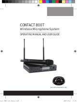
SDR-6210
SDR-6110
UHF 2-Way Sync True Diversity /
Diversity Receiver
CH
FREQSQ
RF AF
A B
0 0 1
63 0
000
VOL
S ET S YN C
P OW ER
SDR-6110 Diversity Receiver

1
SDR-6210/6110
UHF 2-Way Sync True Diversity / Diversity Receiver
Thank you for choosing this wireless microphone system! For more details, please take a few
moments to read this operating manual to have a thorough understanding of the function and
operation of both transmitter and receiver.
In the box
SDR-6210 / 6110 receiver
one transmitter
(handheld / belt-pack)
a pair of antennas
audio cable
switching adaptor
operation manual
** Remark: The above specifications are subject to change without prior notice.
Important
1. Please make sure that the output DC voltage range of the switching power covers that
specified by the receiver before turning it on.
2. The RF meter bars and antenna diversity indicator will appear to denote RF signal received
after turning on the transmitter.
3. The receiver and transmitter must be the same frequency.
4. While using the transmitter, the audio meter bars will appear to denote audio signal received.
RF meter
Antenna selection
Transmitter battery
Channel / frequency
Audio meter
CH
FREQSQ
RF AF
A B
0 0 1
630
000
VOL
SE T SYN C
PO W E R
SD R- 611 0 DiversityReceiver
CH
FREQSQ
RF AF
A B
0 0 1
630
000
VOL

2
Instructions
Parts and functions
Power switch LCD
Function settings on the receiver
VOLUME adjusting
Volume level can be adjusted by the UP(
▲
) and DOWN(
▲
) buttons, from VOL 00 to VOL 15.
CH
FREQSQ
RF AF
A B
0 0 1
63 0
000
VOL
SET
POWER
SYNC
SDR-6110 DiversityReceiver
AN T. A
12V
1. G
2.
3.
BALANCED OUTANT.B OUTPUT LEVEL DC IN
MIC LINE
SET SYNC
VOL
VOL 12
DOWN button
UP button
IR sensor area
SET button
IrDA synchronization button
Antenna A (TNC)
DC input
MIC/LINE output impedance switch,
only for unbalanced audio output.
Unbalanced audio output
Balanced audio output
Antenna B (TNC)

3
SDR-6210/6110
UHF 2-Way Sync True Diversity / Diversity Receiver
CHANNEL scanning
For an interference- free operation, a cleaner channel might be necessary if the current one
receives too much interference. To operate the scanning:
1 Press SET button to make the frequency icon appear on the bottom.
2 Press UP(▲) and DOWN(▲) button to find and locate a clear, interference- free
channel.
3 After a channel is chosen, press SET button or wait 3 seconds to save the setting.
Channel synchronizing between receiver and transmitter
Align infrared areas of the receiver and transmitter within 10~30cm.
FREQ
SET SYNC
CH
FREQ
RF
0 0 2
650.250
SET SYNC
CH
FREQ
RF
0 0 9
652.500
SET SYNC
CH
FREQ
RF
0 0 9
652.500

4
Instructions
Changing the receiver’s channel
1
Press the synchronizing button of the transmitter.
2
The transmitter's LED will glow to denote synchronizing signal transmitted.
3
The channel/frequency of the receiver will change and then the
synchronization is complete.
Changing the transmitter’s channel
1
Press the SYNC button of the receiver
2
The receiver’s LCD will show to denote
synchronizing signal being sent.
3
The channel/frequency of the transmitter will change
and then the synchronization is complete.
If it doesn’t work check that you have the IR sensor panels aligned, that they are facing each
other, devices are within 10~30cm of each other, and try again.
SQUELCH (SQ) adjusting
When interference is encountered try reducing the sensitivity of the receiver, thus less
susceptible to interference. To operate the squelch setting:
1 Press SET button to turn to the squelch setting page and the LCD will display current
squelch level (e.g., LE-02).
2 Press UP(▲) and DOWN(▲) button to select a new squelch (sensitivity) level between
1 and 10.
3 After a squelch (sensitivity) level is chosen, press SET button or wait 3 seconds to
store the setting.
IMPORTANT! Increasing the squelch level will also reduce the reception distance, it’s
recommended to choose the lowest level that can eliminate the interference.
If this still does not solve the problem it means this frequency is not suitable. Adjust the squelch
back to its preset level and use the scan function to locate a clear, interference-free channel.
CH
FREQSQ
RF AF
A B
0 0 1
630
000
VOL
SET
POWER
SYNC
SDR-6110 DiversityReceiver
SET SYNC
SQ
LE-02
SET SYNC
SQ
LE-06
SET SYNC
SQ
LE-06

5
SDR-6210/6110
UHF 2-Way Sync True Diversity / Diversity Receiver
BUTTON LOCK & UNLOCK
1 Press SET button to turn to the BUTTON LOCK page and the LCD will display current
lock status (L-OFF).
2 Press UP(▲) and DOWN(▲) button to switch between L-OFF (unlocked) and L-ON
(locked). The UP(▲) and DOWN(▲) buttons don’t function under L-ON status.
3 After a locking status is chosen, press SET button or wait 3 seconds to store the
setting.
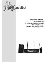
Rack mounting
The receiver can be cabinet-mounted by either one or two units. If only one receiver is to be
mounted, an optional kit is available and it's installed as shown in Fig 1. If two receivers are to
be mounted, they can be assembled by another kit and installed as shown in Fig 2.
Fig 1. Rack mount of one receiver
Fig 2. Rack mount of two receivers
SET SYNC
L-OFF
SET SYNC
L-ON
SET SYNC
L-ON

6
Instructions
Audio output connection
Balanced output
▼
Balanced output:
XLR connector provides balanced audio output signal from this
jack to the mixer/amplifier.
Use an audio output cable with
“XLR” or “Cannon” connector, connect one end to the balanced
output jack of the receiver, and the other end to the “MIC IN”
jack of the mixer/ amplifier.
Unbalanced output:
¼ ” PHONE PLUG connector provides unbalanced audio output
signal from this jack to the mixer/amplifier.
Use an audio output
cable with ¼ ” PHONE PLUG connectors. Connect one end
from the unbalanced output jack of the receiver, and the other
end to the “LINE IN” or “MIC IN” jack of the mixer/ amplifier.
Level switch setting:
When connecting to the LINE /AUX IN of a mixer/amplifier,
switch to “LINE” position. DO NOT use the “MIC” position as
they may not deliver a sufficient high output level.
When connecting to the “MIC IN” jack of a mixer/amplifier, switch to “MIC” position. Overload
distortion may occur at the wrong level position.
to LINE IN
to MIC IN
LINE/AUX IN
MIC IN
Slide output LEVEL to LINE position→
Slide output LEVEL to MIC position→
Unbalanced output ▲
AN T. A
12 V
1.G
2.
3.
BA LAN CE D O UTAN T.B OU TPU T LEV EL DC I N
MIC LINE
AN T. A
12 V
1.G
2.
3.
BA LAN CE D O UTAN T.B OU TPU T LEV EL DC I N
MIC LINE
MIC LINE
LEVEL
MIC LINE
LEVEL
AN T. A
12 V
1.G
2.
3.
BA LAN CE D O UTANT.B OU TPU T LE VEL DC IN
MIC LINE

SDR-6210/6110
UHF 2-Way Sync True Diversity / Diversity Receiver
Receiver installation
For best operation, the receiver should be at least 1m above the
ground and 1m away from a wall or metal surface to minimize
reflections. The transmitter should also be at least 1m away from a wall
or metal surface to minimize reflections. The transmitter should also be
at least 1m away from the receiver. Keep antennas away from noise
source such as motors, automobiles, neon light as well as large metal
objects.
CHIAYO ELECTRONICS CO.,LTD.
Http://www.chiayo.com.tw
|
Email: sales@chiayo.com.tw
Office: 30, Lane 27, Section 4, Jen-Ai Road, Taipei 10685, Taiwan
Tel: 886-2-27415741
|
Fax: 886-2-27525242
Factory: 88, Chung-Hsiao Street 2, Chiayi 60080, Taiwan
Tel: 886-5-2711000
|
Fax: 886-5-5767611
1m
1m
1m
-
 1
1
-
 2
2
-
 3
3
-
 4
4
-
 5
5
-
 6
6
-
 7
7
-
 8
8


Chiayo SDR-6110 IrDA Owner's manual
- Type
- Owner's manual
- This manual is also suitable for
Ask a question and I''ll find the answer in the document
Finding information in a document is now easier with AI
Related papers
-
Chiayo SDR-6120 IrDA Owner's manual
-
-
Chiayo NB-3100 User manual
-
-
Chiayo SDR-8200M IrDA User manual
-
-
Chiayo SDR-6200 IrDA Owner's manual
-
-
-
Other documents
-
Anchor Audio UHF-EXT500-H Owner's manual
-
 Returnstar Interactive Tech IQAudio User manual
-
Nady Systems W1KU User manual
-
 Wharfedale Pro CONTACT 800T User manual
-
-
-
Electro-Voice R300 User manual
-
RCS WR-701 Owner's manual
-
-
 FITNESS AUDIO SM-716 Operating instructions


