Page is loading ...

Manual
LIQ-MAN-TCL-1056, Rev E
July 2017
Rosemount
™
TCL
Total Chlorine System with Rosemount 1056 Transmitter

Essential instructions
Read this page before proceeding!
Rosemount designs, manufactures, and tests its products to meet many national and international standards. Because these
instruments are sophisticated technical products, you must properly install, use, and maintain them to ensure they continue to
operate within their normal specifications. The following instructions must be adhered to and integrated into your safety program
when installing, using, and maintaining Rosemount products. Failure to follow the proper instructions may cause any one of the
following situations to occur: loss of life, personal injury, property damage, damage to this instrument, and warranty invalidation.
• Read all instructions prior to installing, operating, and servicing the product. If this Instruction Manual is not the correct
manual, call 1 800 999 9307, and Rosemount will provide the requested manual. Save this Instruction Manual for future
reference.
• If you do not understand any of the instructions, contact your Rosemount representative for clarification.
• Follow all warnings, cautions, and instructions marked on and supplied with the product.
• Inform and educate your personnel in the proper installation, operation, and maintenance of the product.
• Install your equipment as specified in the installation instructions of this manual and per applicable local and national codes.
Connect all products to the proper electrical and pressure sources.
• To ensure proper performance, use qualified personnel to install, operate, update, program, and maintain the product.
• When replacement parts are required, ensure that qualified people use replacement parts specified by Rosemount.
Unauthorized parts and procedures can affect the product's performance and place the safe operation of your product at
risk. Look alike substitutions may result in fire, electrical hazards, or improper operation.
• Ensure that all equipment doors are closed and protective covers are in place, except when maintenance is being performed
by qualified people, to prevent electrical shock and personal injury.
DANGER!
HAZARDOUS AREA INSTALLATION
Installations near flammable liquids or in hazardous area locations must be carefully evaluated by qualified on site safety personnel.
This device is not intrinsically safe or explosion proof.
To secure and maintain an intrinsically safe installation, the certified safety barrier, transmitter, and sensor combination must be
used. The installaiton system must comply with the governing approval agency (FM, CSA, or BASEEFA/CENELEC) hazardous area
classification requirements. Consult your transmitter instruction manual for details.
Proper installation, operation, and servicing of this device in a hazardous area installation is entirely your responsibility.
WARNING!
ELECTRICAL SHOCK HAZARD
Making cable connections to and servicing this instrument require access to shock hazard level voltages which can cause death or
serious injury.
Be sure to disconnect all hazardous voltage before opening the enclosure.
Relay contacts made to separate power sources must be disconnected before servicing.
Electrical installation must be in accordance with the National Electrical Code (ANSI/NFPA-70) and/or any other applicable national
or local codes.
Unused cable conduit entries must be securely sealed by non-flammable closures to provide enclosure integrity in compliance with
personal safety and environmental protection requirements.
The unused conduit openings need to be sealed with NEMA 4X or IP65 conduit plugs to maintain the ingress protection rating (IP65).
For safety and proper performance, this instrument must be connected to a properly grounded three-wire power source.
Proper relay use and configuration is your responsibility.
No external to the instrument of more than 69 Vdc or 43 V peak allowed with the exception of power and relay terminals. Any
violation will impair the safety protection provided.
Do not operate this instrument without the front cover secured. Refer installation, operation, and servicing to qualified personnel.

WARNING!
This product is not intended for use in the light industrial, residential, or commercial environment, per the instrument's certification
to EN50081-2.
WARNING!
HAZARDOUS VOLTAGE
Can cause severe injury or death. Disconnect power before servicing.
CAUTION!
SENSOR/PROCESS APPLICATION COMPATIBILITY
Wetted materials may not be compatible with process composition and operating conditions. Application compatibility is entirely
your responsibility.
About this document
This manual contains instructions for installation and operation of the Rosemount TCL
1056 Total Chlorine Transmitter.
The following list provides notes concerning all revisions of this document.
Rev level Date Notes
A 07/07 This is the initial release of the product manual. This manual has been reformatted to
reflect the Emerson documentation style and updated to reflect any change in the prod-
uct offering.
B 11/07 Page 3 additions to Section 1.2, page 5 changes to the Analyzer (option selection) table,
page 14 updated the caution box, and page 15 updated Section 4.3.3.
C 07/10 Updated DNV logo.
D 05/11 Revised Chapter 1, replaced Figure 3-3, revised Section 4.3.3, replaced Figure 4-4, added
to Chapter 8, and revised Section 11.7.2.
E 07/17 Changed instances of analyzer to transmitter. Updated formatting to align with new
branding guidelines. Updated addresses on back page.


Contents
Chapter 1 Description and specifications ........................................................................................1
1.1 Features .......................................................................................................................................1
1.2 Specifications ...............................................................................................................................2
1.3 Ordering information and accessories ..........................................................................................5
Chapter 2 Principles of operation ................................................................................................... 9
Chapter 3 Installation ...................................................................................................................11
3.1 Unpacking and inspection ..........................................................................................................11
3.2 Installation .................................................................................................................................11
3.2.1 General information .................................................................................................... 11
3.2.2 Install the transmitter ..................................................................................................11
3.2.3 Install the sample conditioning enclosure ....................................................................13
3.2.4 Install the sensor ......................................................................................................... 16
Chapter 4 Wiring ..........................................................................................................................19
4.1 Prepare transmitter conduit openings ........................................................................................19
4.2 Provide power to the sample conditioning system .....................................................................19
4.3 Make power, alarm, output, and sensor connections in the transmitter ..................................... 20
4.3.1 Power ..........................................................................................................................20
4.3.2 Analog output wiring .................................................................................................. 21
4.3.3 Alarm wiring ................................................................................................................22
4.4 Sensor wiring ............................................................................................................................. 22
4.5 Apply power to the transmitter and complete Quick Start ......................................................... 24
Chapter 5 Startup .........................................................................................................................27
5.1 Prepare the reagent ................................................................................................................... 27
5.2 Zero the sensor .......................................................................................................................... 28
5.3 Start sample flow ....................................................................................................................... 28
5.4 Begin operation and calibrate the sensor ................................................................................... 28
Chapter 6 Display and operation .................................................................................................. 29
6.1 Display .......................................................................................................................................29
6.2 Keypad .......................................................................................................................................30
6.3 Programming the transmitter - tutorial ......................................................................................32
6.4 Security ......................................................................................................................................34
6.4.1 How the security code works .......................................................................................34
6.4.2 Assigning security codes ............................................................................................. 34
6.4.3 Bypassing security codes ............................................................................................. 34
6.5 Using hold ..................................................................................................................................35
6.5.1 Purpose .......................................................................................................................35
6.5.2 Using the hold function ............................................................................................... 35
6.6 Configuring the main display ..................................................................................................... 36
Chapter 7 Programming the transmitter ...................................................................................... 39
7.1 General ...................................................................................................................................... 39
7.2 Default settings ......................................................................................................................... 39
7.3 Configuring, ranging, and simulating outputs ............................................................................41
7.3.1 Purpose .......................................................................................................................41
7.3.2 Definitions ...................................................................................................................41
Contents
Instruction Manual i

7.3.3 Procedure - configure outputs .....................................................................................42
7.3.4 Procedure - ranging outputs ........................................................................................43
7.3.5 Procedure - simulating outputs ................................................................................... 44
7.4 Configuring alarms and assigning setpoints ............................................................................... 46
7.4.1 Purpose .......................................................................................................................46
7.4.2 Definitions ...................................................................................................................46
7.4.3 Procedure - configuring alarms and assigning setpoints .............................................. 48
7.4.4 Procedure - simulating alarms ..................................................................................... 50
7.4.5 Procedure - synchronizing timers ................................................................................ 51
7.5 Configuring the measurement ...................................................................................................52
7.5.1 Purpose .......................................................................................................................52
7.5.2 Definitions ...................................................................................................................52
7.5.3 Procedure - configuring the measurement .................................................................. 52
7.6 Configuring temperature related settings ..................................................................................53
7.6.1 Purpose .......................................................................................................................53
7.6.2 Definitions - chlorine ................................................................................................... 54
7.6.3 Procedure - configuring temperature related settings ................................................. 54
7.7 Configuring security settings ..................................................................................................... 55
7.7.1 Purpose .......................................................................................................................55
7.7.2 Procedure - configuring security settings .................................................................... 56
7.8 Resetting the transmitter ...........................................................................................................56
7.8.1 Purpose .......................................................................................................................56
7.8.2 Procedure - resetting the transmitter .......................................................................... 57
Chapter 8 Digital communications ............................................................................................... 59
Chapter 9 Calibration ................................................................................................................... 61
9.1 Introduction ...............................................................................................................................61
9.2 Calibrating temperature ............................................................................................................ 61
9.2.1 Purpose .......................................................................................................................61
9.2.2 Procedure ....................................................................................................................61
9.3 Calibrating total chlorine ........................................................................................................... 63
9.3.1 Purpose .......................................................................................................................63
9.3.2 Procedure - zeroing the sensor .................................................................................... 65
9.3.3 Procedure - calibrating the sensor ............................................................................... 67
9.4 Calibrating analog outputs .........................................................................................................69
9.4.1 Purpose .......................................................................................................................69
9.4.2 Procedure ....................................................................................................................69
Chapter 10 Maintenance ................................................................................................................ 71
10.1 Transmitter ................................................................................................................................71
10.2 Total chlorine sensor ..................................................................................................................72
10.2.1 General ....................................................................................................................... 72
10.2.2 Cleaning the membrane ..............................................................................................72
10.2.3 Replacing the membrane ............................................................................................ 72
10.2.4 Replacing the electrolyte solution and membrane .......................................................73
10.3 Sample conditioning system ......................................................................................................74
10.3.1 Reagent .......................................................................................................................74
10.3.2 Sample and reagent tubing ......................................................................................... 75
10.3.3 Replacing sample tubing ............................................................................................. 76
10.3.4 Peristaltic pump tubing ............................................................................................... 77
10.3.5 Replacing the air pump ............................................................................................... 80
10.3.6 Replacing the air pump diaphragm and check valves ...................................................82
Contents
ii Rosemount TCL

Chapter 11 Troubleshooting .......................................................................................................... 85
11.1 Overview ................................................................................................................................... 85
11.2 Using the diagnostic feature ...................................................................................................... 85
11.3 Troubleshooting when a Fault message is showing .................................................................... 86
11.3.1 Main Board CPU, Main Board Factory Data, and Main Board User Data errors ...............86
11.3.2 Hardware Error ............................................................................................................87
11.3.3 Sensor Board Unknown, Sensor Board HW (Hardware) or SW (Software) Mismatch, or
Sensor Board Not Communicating
.............................................................................. 87
11.3.4 Sensor Incompatible ................................................................................................... 87
11.3.5 Sensor CPU Error ......................................................................................................... 87
11.3.6 Sensor RTD open .........................................................................................................88
11.3.7 Sensor 1 Not Detected ................................................................................................ 88
11.3.8 Sensor Factory Data, Sensor Board User Data, and Sensor EEPROM Write errors ..........88
11.3.9 Sensor ADC error .........................................................................................................88
11.3.10 Sensor RTD Out of Range ............................................................................................ 88
11.4 Troubleshooting when a Warning message is showing .............................................................. 89
11.4.1 Sensor Need Factory Cal ..............................................................................................89
11.4.2 Sensor Negative Reading .............................................................................................89
11.4.3 Sensor RTD Sense Open .............................................................................................. 89
11.4.4 Sensor Temperature High or Low ................................................................................ 90
11.5 Troubleshooting when no error message is showing ..................................................................90
11.5.1 Zero current is too high. .............................................................................................. 91
11.5.2 Zero current is unstable. ..............................................................................................91
11.5.3 Sensitivity is low or readings are low. ...........................................................................91
11.5.4 Process readings are erratic or wander. ....................................................................... 93
11.5.5 Readings drift. .............................................................................................................94
11.5.6 Readings are too high ..................................................................................................94
11.5.7 Temperature was more than 3 °C different from transmitter ....................................... 94
11.5.8 Current output is too low. ........................................................................................... 94
11.5.9 Alarm relays don't work. .............................................................................................. 94
11.6 Simulating inputs .......................................................................................................................95
11.7 Simulating temperature .............................................................................................................95
11.7.1 General ....................................................................................................................... 95
11.7.2 Simulating temperature .............................................................................................. 96
Chapter 12 Return of material ........................................................................................................ 99
Contents
Instruction Manual iii

Contents
iv Rosemount TCL

1 Description and specifications
1.1 Features
Rosemount TCL Sample Conditioning System
The sample conditioning system permits a single sensor to measure total chlorine in water.
The sample conditioning system continuously injects a solution of acetic acid (vinegar) and
potassium iodide into the sample. The acid lowers the pH to between 3.5 and 4.5 and
allows total chlorine in the sample to quantitatively react with the potassium iodide to
produce iodine. The sensor measures the iodine concentration, and the transmitter
displays the total oxidant concentration in ppm as Cl
2
.
Rosemount 1056 Transmitter
The Rosemount 1056 Transmitter measures total chlorine when used with the 499ACL-02
Sensor and TCL Sample Conditioning System.
The Rosemount 1056 Transmitter is housed in a corrosion resistant NEMA 4X enclosure. It
is suitable for panel, pipe, or wall mounting. You can operate the transmitter with a
membrane keypad. A back-lit, six line display shows the total chlorine reading and
temperature in 0.6 in. (15 mm) high characters. The display can be customized to show
other information, for example, output signal and diagnostics.
Calibration and programming screens are simple and intuitive. Plain language prompts in
six languages guide you through procedures. Information and diagnostic screens, as well
as basic troubleshooting guidelines are available at the touch of a button.
The Rosemount 1056 Transmitter has two isolated, continuously variable 4-20 mA
outputs. Outputs can be assigned to total chlorine concentration or to temperature.
Digital communications, HART or Profibus DP, are available as options.
Four fully programmable alarm relays are available as an option. Relays can be assigned to
total chlorine concentration or temperature. A relay can also be used to signal a fault
condition. An alarm activates when a transmitter or sensor fault occurs.
Rosemount 499ACL-02 Total Chlorine Sensor
The Rosemount 499ACL-02 Total Chlorine Sensor is used in the TCL Sample Conditioning
System. Although the sensor is called a chlorine sensor, it really measures iodine. The
iodine comes from the reaction between oxidants in the sample and the acetic acid/
potassium iodide reagent added by the sample conditioning system.
The sensor consists of a gold cathode and a silver anode in an electrolyte solution. A
silicone membrane, permeable to iodine, is stretched over the cathode. The transmitter
applies a voltage to the cathode sufficiently negative to reduce all the iodine reaching it.
Because the concentration of iodine in the sensor is always zero, a concentration gradient
continuously forces iodine from the sample through the membrane into the sensor.
Description and specifications
Instruction Manual 1

The reduction of iodine in the sensor generates a current directly proportional to the
diffusion rate of iodine through the membrane, which is directly proportional to the
concentration of iodine in the sample. Because the iodine concentration depends on the
amount of total chlorine in the sample, the sensor current is ultimately proportional to the
total chlorine concentration.
The permeability of the membrane to iodine is a function of temperature. A Pt100 RTD in
the sensor measures the temperature, and the transmitter uses the temperature to
compensate the total chlorine reading for changes in membrane permeability.
Sensor maintenance is fast and easy. Replacing the membrane requires no special tools or
fixtures. Simply place the membrane assembly on the cathode and screw the retainer in
place. Installing a new membrane and replenishing the electrolyte takes only a few
minutes.
1.2 Specifications
Sample Conditioning SystemTable 1-1:
Physical characteristics Specifications
General
Enclosure Fiberglass reinforced polyester, NEMA 3 (IP53)
suitable for marine environments
Dimensions 14.5 x 13.0 x 8.6 in. (369 x 329 x 218 mm)
Mounting Wall
Ambient temperature 0 to 50 °C (32 to122 °F)
Ambient humidity 0 to 90% (non-condensing)
Power 115 Vac, 6.9 W, 50/60 Hz
230 Vac, 7.0 W, 50/60 Hz
Hazardous location The TCL Sample Conditioning System has no
hazardous location approvals.
Pumps
EN 809:1998
Weight/shipping weight 14 lb/16 lb (6.5 kg/7.5 kg)
Sample requirements
Inlet connection Compression fitting, accepts 1/4 in. OD tubing
Drain connection 3/4 in. barbed fitting (must drain to open at-
mosphere)
Inlet pressure <100 psig (791 kPa abs)
Flow At least 0.25 gph (15 mL/min)
Temperature 0 to 50 °C (32 to122 °F)
Total alkalinity <300 mg/L as CaCO
3
. For samples containing
<50 mg/L alkalinity, consult the factory.
Description and specifications
2 Rosemount TCL

Sample Conditioning System (continued)Table 1-1:
Physical characteristics Specifications
Sample conditioning system
Reagent Potassium iodide in vinegar
Reagent usage 5 gallons last approximately 60 days.
Reagent pump Fixed speed peristaltic pump, about 0.2 mL/min
Sample pump Fixed speed peristaltic pump, about 11 mL/min
Rosemount 1056 TransmitterTable 1-2:
Physical characteristics Specifications
Case Polycarbonate, NEMA 4X/CSA 4 (IP65)
Dimensions 6.10 x 6.10 x 5.15 in. (155 x 155 x 131 mm)
Conduit openings Accepts PG13.5 or 1/2 in. conduit fittings
Display Monochromatic back-lit LCD. Main character height 0.6
in. (15 mm). Display is programmable.
Languages English, French, German, Italian, Spanish, and Portu-
guese
Ambient temperature and humidity 0 to 55 °C (32 to 131 °F); relative humidity 5 to 95% (non-
condensing).
Storage temperature -20 to 60 °C (-4 to 140 °F)
Power Code -01: 115/230 Vac ±15%, 50/60 Hz, 10 W.
Code -03: 85 to 265 Vac, 47.5 to 65.0 Hz, 15 W (includes
four relays).
Equipment protected by double insulation.
Hazardous location approvals Applies to transmitter only.
Class 1, Division 2, Groups A, B, C, & D
Class II, Division 2, Groups E, F, & D
Class III, T4 Tamb = 50 °C
Evaluated to the ANSI/UL Standards. The C and US indica-
tors adjacent to the CSA mark signify that the product
has been evaluated to the applicable CSA and ANSI/UL
Standards, for use in Canada and the US, respectively.
RFI/EMI
LVD
EN-61326
EN-6101-01
Outputs Two 4-20 mA or 0-20 mA isolated outputs. Continuously
adjustable. Linear or logarithmic. Maximum load 550
ohms. Output dampening with a time constant of 5 sec is
user-selectable.
Description and specifications
Instruction Manual 3

Rosemount 1056 Transmitter (continued)Table 1-2:
Physical characteristics Specifications
Alarms Four alarm relays for process measurement(s) or temper-
ature. Any relay can be configured independently, and
each can be programmed with interval timer settings.
Relays Form C, SPDT, epoxy sealed
Relay contact ratings
5 A at 28 Vdc or 300 Vac (resistive)
1/8 HP at 120/240 Vac
Terminal connections rating Power connector (3-leads): 18-12 AWG wire size. Current
output connectors (2-leads): 24-16 AWG wire size. Alarm
relay terminal blocks: 18-16 AWG wire size
Weight/shipping weight (rounded up
to nearest 1 lb or 0.5 kg)
3 lb/4 lb (1.5 kg/2.0 kg)
Rosemount 499ACL-02 Total Chlorine SensorTable 1-3:
Physical characteristics Specifications
Wetted parts Gold, Noryl
®
(1)
(PPO), Viton
®
(2)
, EPDM, and sili-
cone
Dimensions 1.0 x 5. 6 in. (25.4 x 143 mm)
Cable 25 ft (7.6 m) standard
Pressure rating 0 to 65 psig (101 to 549 kPa)
Temperature rating 0 to 50 °C (32 to 122 °F)
Electrolyte capacity Approximately 25 mL
Electrolyte life Approximately 4 months
Weight/shipping weight 1 lb/3 lb (0.5 kg/1.5 kg)
(1) Noryl is a registered trademark of General Electric.
(2)
Viton is a registered trademark of DuPont Performance Elastomers.
Description and specifications
4 Rosemount TCL

Performance Specifications - Complete SystemTable 1-4:
Physical characteristics Specifications
Linear range 0 to 20 ppm (mg/L) as Cl
2
(for higher ranges,
consult factory)
Linearity (per ISO 15839) 0 to 10 ppm: 2%; 0 to 20 ppm: 3%
Response time Following a step change in concentration, the
reading reaches 90% of final value within 7 mi-
nutes at 25 °C (77 °F)
Drift At about 1.5 ppm in clean water and constant
temperature, drift is typically less than 0.05
ppm over two weeks.
Detection limit (per ISO 15839) 0.02 ppm (mg/L) in clean water at room tem-
perature
1.3 Ordering information and accessories
Rosemount TCL Reagent-Based Chlorine System
The TCL is used for the continuous determination of total chlorine in water. The TCL
consists of a sample conditioning system, a reagent carboy, a sensor, and a transmitter.
Important
Reagent kits must be ordered separately. Reagent kits for 0-5 ppm and 0-10 ppm chlorine are
available. For higher ranges, consult the factory.
See Table 1-5.
Rosemount TCL Total Chlorine System Ordering InformationTable 1-5:
Model Sensor type
TCL Total Chlorine System
Power input
11 115 Vac 50/60 Hz
12 230 Vac 50/60 Hz
Transmitter
- No selection - no transmitter
270 Rosemount 1056-01-24-38-AN, no relays, analog output
271 Rosemount 1056-01-24-38-HT, no relays, HART
®
272 Rosemount 1056-01-24-38 DP, no relays, Profibus DP
273 Rosemount 1056-03-24-38-AN, alarm relays, analog output
274 Rosemount 1056-03-24-38-HT, alarm relays, HART
Description and specifications
Instruction Manual 5

Rosemount TCL Total Chlorine System Ordering Information (continued)Table 1-5:
275 Rosemount 1056-03-24-38-DP, alarm relays, Profibus DP
Sensor
- No selection - no sensor
30 Rosemount 499ACL-02-54 Total Chlorine Sensor with standard cable
31 Rosemount 499ACL-02-54-60 Total Chlorine Sensor with optimum EMI/RFI ca-
ble
32 Rosemount 499ACL-02-54-VP Total Chlorine Sensor with VP cable connector
(1)
Typical model number: TCL-11-280-32
(1) Interconnecting VP cable sold separately.
Accessories
Sample Conditioning System AccessoriesTable 1-6:
Part number Description
24134-00 Air pump, 115 Vac, 50/60 Hz
24134-01 Air pump, 230 Vac, 50/60 Hz
9160578 Air pump repair kit
9322052 Check valve for air injection line
24153-00 Carboy for reagent, 5 gal/19 L, includes cap
9100204 Fuse, 0.25 A, 250 V, 3 AG, slow blow for option-11
(115 Vac)
9100132 Fuse, 0.125 A, 250 V, 3 AG, slow blow for option -12
(230 Vac)
9380094 Reagent pump, 115 Vac, 50/60 Hz
9380095 Reagent pump, 230 Vac, 50/60 Hz
9380091 Reagent pump replacement tubing
24151-00 Reagent tubing replacement kit
24135-00 Reagent uptake tubing, 6 ft (1.8 m), includes weight
9380090 Sample pump, 115 Vac, 50/60 Hz
9380093 Sample pump, 230 Vac, 50/60 Hz
9380092 Sample pump replacement tubing
24152-00 Sample tubing replacement kit
24164-00 Potassium iodide, 25 g, sufficient for 5 gallons (19 L) of
vinegar (0-5 ppm total chlorine)
24164-01 Potassium iodide, 50 g, sufficient for 5 gallons (19 L) of
vinegar (0-10 ppm total chlorine)
24165-00 Acetic acid, 2 x 2.5 gal (9.5 L) bottles/case, with 25 g po-
tassium iodide (0-5 ppm total chlorine)
Description and specifications
6 Rosemount TCL

Sample Conditioning System Accessories (continued)Table 1-6:
Part number Description
24165-01 Acetic acid, 2 x 2.5 gal (9.5 L) bottles/case, with 50 g po-
tassium iodide (0-10 ppm total chlorine)
Rosemount 1056 and 56 Transmitters AccessoriesTable 1-7:
Part number Description
23554-00 Cable glands (qty 5 of PG 13.5)
23820-00 Wall and 2 in. pipe mounting kti
240048-00 Stainless steel tag (specify marking)
Sensor AccessoriesTable 1-8:
Part number Description
23501-02 Total chlorine membrane, includes 1 membrane assembly
and 1 O-ring
23502-02 Total chlorine membrane kit, includes 3 membrane as-
semblies and 3 O-rings
9210438 Total chlorine sensor fill solution, 4 oz (120 mL)
For First Time Variopol InstallationsTable 1-9:
Part number Description
23747-06 Interconnecting cable, VP 6, 2.5 ft (0.8 m)
23747-04 Interconnecting cable, VP 6, 4 ft (1.2 m)
23747-02 Interconnecting cable, VP 6, 10 ft (3.0 m)
23747-07 Interconnecting cable, VP 6, 15 ft (4.6 m)
23747-08 Interconnecting cable, VP 6, 20 ft (6.1 m)
23747-09 Interconnecting cable, VP 6, 25 ft (6.1 m)
23747-10 Interconnecting cable, VP 6, 30 ft (9.1 m)
23747-03 Interconnecting cable, VP 6, 50 ft (15.2 m)
23747-11 Interconnecting cable, VP 6, 100 ft (30.5 m)
Description and specifications
Instruction Manual 7

Description and specifications
8 Rosemount TCL

2 Principles of operation
Total chlorine by definition is the iodine produced in a sample when it is treated with
potassium iodide at a pH between 3.5 and 4.5. Typically, acetic acid (or vinegar) is used to
adjust the pH.
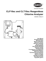
The total chlorine system consists of a sample conditioning system, which injects the
reagent into the sample, and a sensor and transmitter, which measure the amount of
iodine produced. Figure 2-1 shows the sample conditioning system. The sample enters the
sample conditioning enclosure and flows to an overflow sampler from which the sample
pump takes suction. Excess sample drains to waste. At the same time, the reagent pump
draws reagent, a solution of potassium iodide in vinegar, from the reagent carboy and
injects it into the suction side of the sample pump. The sample and reagent mix as they
pass through the pump, and total chlorine in the sample is converted to the chemically
equivalent amount of iodine. The flow rates are 11 mL/min for the sample and 0.2 mL/min
for the reagent.
Schematic of Sample Conditioning System and TransmitterFigure 2-1:
The treated sample next enters the flow cell. Bubbles injected into the flow cell produce
turbulence, which improves the stability of the reading. A membrane-covered
amperometric sensor in the flow cell measures the concentration of iodine. The
transmitter receives the raw signal from the sensor and displays the concentration of total
chlorine. Display units are ppm (mg/L) chlorine as Cl
2
. The treated sample leaves the flow
cell and drains to waste along with the excess sample.
Principles of operation
Instruction Manual 9

Principles of operation
10 Rosemount TCL

3 Installation
3.1 Unpacking and inspection
Complete the following steps when you unpack your instrument.
1. Inspect the shipping containers. If there is damage, contact the shipper immediately
for instructions.
2. If there is no apparent damage, unpack the containers.
3. Ensure that all items shown on the packing list are present. If items are missing,
notify Rosemount immediately.
3.2 Installation
3.2.1 General information
1. Although the transmitter and sample conditioning system are suitable for outdoor
use, do not install them in direct sunlight or in areas of extreme temperature.
CAUTION!
HAZARDOUS AREAS
The TCL Total Chlorine Sample Conditioning System is not suitable for use in hazardous
areas.
2. Install the transmitter and sample conditioning system in an area where vibrations
and electromagnetic and radio frequency interference are minimized or absent.
3. Keep the transmittter and sensor wiring at least one foot from high voltage
conductors. Be sure there is easy access to the transmitter and sample conditioning
system.
4. The transmitter is suitable for panel, pipe, or wall mounting. The sample
conditioning enclosure must be mounted on a wall. Provide adequate room beneath
the enclosure for the 5-gallon reagent carboy.
5. Be sure that the distance between the transmitter and sample conditioning cabinet
does not exceed the length of the sensor cable.
3.2.2 Install the transmitter
1. Refer to the appropriate figure for installation details.
Type of mounting Figure
Panel Figure 3-1
Installation
Instruction Manual 11

/