Page is loading ...

VCIOM-01600-EN 17/11
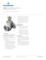
FASANI ASSISTED SWING CHECK VALVE BOLTED BONNET
INSTALLATION AND MAINTENANCE INSTRUCTIONS
© 2017 Emerson. All Rights Reserved.
INTRODUCTION
Actuator or Counterweight assisted,
flanged or welded ends.
This manual provides guidelines to be observed
for the following operations:
• storage
• installation into the pipeline
• maintenance
• preservation
The manual is intended for the following
personnel/staff:
• plant warehouse staff
• installers
• maintenance engineers
VERIFICATION UPON RECEIPT AND STORAGE
Before start-up:
• On arrival of materials, it is recommended to:
- Check the integrity of the case/packing.
- Open the case and verify that there is no
damage due to transportation.
- Do not open the barrier bag - if any.
- Verify that the content matches the packing
list.
- Store the valves in their original packing
(unless damaged). When doing so, please
observe the following:
- Store the valves in a closed, clean and dry
storage room.
- Do not place the packages directly on the
ground.
- Check the packages every two months.
- Substitute the silica gel every six months
(not applicable in the case of barrier bag).
• For actuated valves, in addition to the above,
please refer to the actuator manual.
Emerson.com/FinalControl
In addition to the instructions in this manual,
specific plant safety regulations must always
be followed.
Before starting any maintenance activity,
it is strongly recommended to read carefully
and completely this manual. It is also
recommended to verify the availability of
the suggested spare parts, so you can always
assemble the valve and minimize intervention
time.
For installation and maintenance operations no
specific equipment or tools are required, other
than those usually available in the plant.
Emerson is always at the customer’s disposal
for further technical information.
WARNING
Do not use the valve as an interception valve for
cleaning the line.
Maximum admitted velocity for fluids:
6m/s for liquids
80m/s for gas or steam/vapour
Before installation these instructions must be fully read and understood

2
FASANI ASSISTED SWING CHECK VALVE BOLTED BONNET
INSTALLATION AND MAINTENANCE INSTRUCTIONS
INSTALLATION
For correct operation of the valve, this must
be installed in horizontal position only as
indicated in Fig. 2. Different positions from
those indicated may cause non-correct valve
operation and/or quick deterioration of the
valve.
The following operations must be performed
only immediately before the installation:
1. Remove the protection caps of the end
faces.
2. Remove pin protection.
3. Check the pipeline sections upstream and
downstream. Make sure that there are no
solid particles or any other kind of dirt or
debris inside. If necessary, clean carefully
by using an airline.
4. Verify the flow direction in the line.
WARNING
Protect eyes with appropriate welding masks or
goggles during all welding operations.
WARNING
Verify that the direction of the line corresponds
to the flow direction indicated by the arrow on the
valve body.
Make sure that the materials of construction
listed on the valve nameplates (service and
temperature), are appropriate for the service and
fluid of the plant.
Flanged valves
Place the valve between the two pipe flanges,
and the gasket between the valve’s flange
and the pipe’s flange. Make sure that it is
positioned in the center. Assemble the valve to
the pipe by tightening the bolts according to the
torques given by the Engineering Company that
designed the plant.
Butt-welding valves
Position the valve and verify its alignment
with the pipe. Proceed with the welding in
accordance with the procedure indicated by the
Engineering Company that designed the plant.
Usually, the first weld layer will be made with
TIG, while following weld layers will be made
with the appropriate electrode for the valve
body material.
General notes
• Should one end not be connected to the line
for longer than half a day, the open end must
be properly closed and sealed in order to
prevent entry of dirt or debris.
• After the installation of the valve and before
the line testing, it is strongly recommend
cleaning the line in order to remove dirt
and/or foreign bodies that may damage the
tightness between the seat and the disc, and
the correct operation of the valve.
• We strongly recommend checking the torque
of the body-bonnet bolts, especially if the
valve is to operate at high temperatures.
Tightening must be done alternatively on
the bolts that are diametrically opposed, see
Fig. 3. The torque values are those reported
in Table 3.
FIGURE 2 - POSITION FOR VALVE INSTALLATION
2˚ max
2˚ max
FIGURE 3 - TIGHTEN BOLTS - FLANGE
TIGHTENING SEQUENCE
HANDLING
During handling operations, valves must be
lifted and handled as indicated in Fig. 1 by using
lifting equipment respecting the carrying limits
(valve weight indicated in the drawings).
Optional eyebolts on the valve body can be used
to lift the valve.
WARNING
• Do not use any lifting equipment that is either
damaged or/and of an inadequate/unknown size.
• Do not use the eyebolt in the bonnet to lift the
valve.
FIGURE 1 - VALVE LIFTING AND HANDLING
FIGURE 4 - CONNECTION FOR DRAINING
Drain in ‘G’ position
2˚ max
2˚ max
Flow
Drain connection
Draining connection in the valve body (Fig.4) to
be connected to plant draining system before
putting valve in operation. In case of lack of
draining, condensate retained in the valve
bottom could flash generating pressure peaks
which may damage the valve and/or other
equipments in the plant.

3
FASANI ASSISTED SWING CHECK VALVE BOLTED BONNET
INSTALLATION AND MAINTENANCE INSTRUCTIONS
START UP REQUIREMENTS
Before the start up of the plant, we recommend
to:
• Check that the lines have been accurately
cleaned.
• If the valve has been stocked for a long time
and should operate at high temperatures,
verify the tightness of the body/bonnet bolts.
Tightening must be done alternatively on
the bolts that are diametrically opposed.
See Fig. 3. The torque values are those
reported in Table 3.
• Check the tightness of the gland bolts.
• Check that the pin’s protection has been
removed.
• Check electrical, pneumatic and hydraulic
connection - if any.
• Check that the drain in the valve body is
properly connected to the plant draining
system.
• Check that the actuator is properly installed
according to section 8.
• Check that the torque/travel switches
are properly set according to actuator
maintenance manual.
SCHEDULED MAINTENANCE
Routine inspections
• Monthly check that there is no leakage from
the body/bonnet area.
• In case of leakage from the body/bonnet area,
tighten the appropriate the bolts according to
the sequence in Fig. 3.
• In addition to the above, please refer to the
actuator manual.
Preventive
• Check the space between the gland and
the bonnets every 12 months. In case of a
reduction of the space, restore the space by
installing a new ring packing.
• Remove the bonnet of the valve every 4 years.
Check the inside and verify that the valve
is not damaged, especially the disc pin and
the bushes. Re-lap the seats if necessary
and replace the body/bonnet gasket and the
packing.
• After 4 years operation, replace bushes 108
and 126.
• Disassemble the valve every 8 years.
Recondition the seats, replace the bushes,
the anti-clutch spacer, the gasket, the
packing and the keys. It is recommended
having a pin available during the operation.
• For the actuator, proceed as indicated in its
maintenance manual.
WARNING
An incorrect connection of the actuator is
dangerous and may cause irreversible damages
to the valve.
WARNING
The actuator should be energized before the
start up of the plant, in order to avoid damages
to the valve, and to minimize drops of charge,
maximizing the performance of the plant.
• During the start-up of the plant, verify the
packing seal. In case of leakage, tighten the
bolts alternatively.
• During the start-up, for the valves equipped
with lever and external counterweight, make
sure the counterweights are in the right
position for the intended service.
Under regular service conditions, operate
the lever in the sense of close position. When
discharged the lever should return by itself
to its former position. Without fluid in the
valve, the disc shall position itself in the close
position.

4
FASANI ASSISTED SWING CHECK VALVE BOLTED BONNET
INSTALLATION AND MAINTENANCE INSTRUCTIONS
TROUBLESHOOTING GUIDE
Problems reported are not exhaustive,
they represent the most frequent ones.
Leakage from the packing
In case of leakages from the packing that
cannot be stopped by tightening the gland bolts,
proceed as follows.
• Packing may have hardened. In this case,
it must be replaced.
• The distance between the gland and the
bonnet is reduced. Thus, the packing cannot
be compressed. Packing must be replaced.
• Scratches or other marks are found on the
pin or the pin itself is bent. In these cases,
the pin must be replaced.
• The gland may be jammed on the pin because
of a non-uniform tightness of the gland
bolts. Loosen the gland bolts. Move the
gland and set it again; then tighten the bolts
progressively and uniformly.
DISASSEMBLING INSTRUCTIONS
Here below are the procedures to follow
to disassemble valves. Before starting any
operation, it is important to:
• identify the problem
• clean the area around the valve that is to be
disassembled
• prepare a box and/or a pallet where to collect
all pieces
• prepare a polyethylene sheet to protect all
components and to prevent particles from
entering the body of the valve.
For all the above cases it is absolutely
necessary to disassemble the valve as soon
as possible and perform an inspection of
the internal parts in order to reduce further
damage.
Leakage from the body/bonnet joint
• A leakage from the body/bonnet joint may be
the consequence of a long storage time of the
valve. The gasket may have lost elasticity and/
or the bolts may have loosened.
In the first case, the leakage will
progressively decrease, the gasket regaining
part of its elasticity with the contact of the
process fluid. A verification of the bolts
tightness will contribute to stop the leakage.
In the second case, bolts should be tightened
according to Fig. 3.
Usually these two actions are combined.
• Leakage under operation of the plant
requires the tightening of the bolts and
the replacement of the gasket as soon as
possible.
Leakage between seat and disc
In case of leakage between seat and disc,
check that:
• No foreign material is locked between seat
and disc, scratching the sealing surfaces.
• No foreign material is laid down between
the seats, preventing the disc from closing.
• During a previous closure the fluid has
laminated the seal surfaces, eroding these.
Jamming of valve along the stroke
If a higher torque is required at some points
when opening/closing the valve, proceed as
follows:
• Disassemble the valve, as body guides and
disc may start to seize.
Problems regarding motor operation
• Please, refer to the actuator instruction
manual.
During disassembling operations, identify all
pieces to keep track of the position/orientation
of the parts regarding the valve body.
WARNING
Before starting disassembling any part of the
valve it is very important to verify - for your safety
- that:
• the line is not pressurized
• the valve is not in temperature
• all electrical, pneumatic and/or hydraulic
devices have been switched off and
disconnected.
Actuator disassembling
1. Hold the actuator using the eyebolts with a
strip suitable to its weight.
2. Remove the bolts (79) that join the actuator
and the valve’s flange together
3. Remove the actuator from the pin of the
valve. If necessary use a lever between the
valve and the flange of the actuator.
Counterweight disassembling
1. Hook the counterweight’s opening
protection structure (276) with a steel
thread.
2. Remove the bolts that close the protection
of the counterweight and the opening itself.
3. Hold the counterweight’s lever (107) with a
strip. Then remove the blocking nut (115)
and the washer (211).
4. Hold the strip tight and remove the
counterweight. If necessary use a lever.

5
FASANI ASSISTED SWING CHECK VALVE BOLTED BONNET
INSTALLATION AND MAINTENANCE INSTRUCTIONS
ASSEMBLING INSTRUCTIONS
Before starting reassembling is recommended
to verify the following points:
• Remove any dirt or particles with a wire brush
or abrasive cloth; remove any oil or grease
with a suitable solvent, to avoid damage
caused by foreign particles - in particular on
the sealing area.
• Never re-use the old gaskets, even though
they seem to be in good condition.
• During reassembling operations, match the
punched pieces so that they are correctly
assembled.
Packing assembling
1. Remove gland nuts (16) and bolts (15).
2. Lift the gland flange (10) and the gland (9).
3. Remove the used packing by means of a
steel hook-shaped thread.
4. For a better sealing, carefully clean the
packing room and the shaft. Make sure that
they are not damaged (scratches) and there
are not seizing signs.
5.
The packing assembly must be done by
placing, in the packing room, one ring at a
time. Be careful to allocate them correctly and
press them to the bottom of the packing room.
6. Once the packing room is full, replace the
gland (9) and the gland flange (10) to their
original positions.
Body/bonnet gasket replacement
1. Before replacing the body/bonnet gasket,
clean the body/bonnet flange’s surfaces
carefully.
2. Fit the gasket in the seat, then align in
a parallel position the bonnet flange with
the flange in which the gasket is placed.
Do not use the bolts to align.
3. While tightening, make sure that the
flange’s pairing is completely parallel.
4. Tighten the bolts according to fig.3. In the
first tightening be careful to apply 1/4 of the
final torque reported in Table 3. For a better
performance of the joint, tight again all bolts
once the installation is started up.
Removal of valves welded to the line
Shall the valve need to be removed from the
line, cut the pipe far from the welding point so
that the valve’s gauge can be restored.
Disassembling of the disc
1. In order to remove the disc, the actuator
and the counterweight have to be previously
removed.
2. Remove the bolts between the body and the
bonnet (11). Place them in a clean space.
3. Lift the bonnet (6) by means of a strip and a
hoist and hold it to the eyebolt.
4. Hold the hinge pin and the disc together
(45-3). Place the strip between the hinge pin
and the disc and hold it by means of a hoist.
5. Remove the gland bolts (16), the gland
flange (10), and the gland (9) from the side
of the actuator and from the side of the
counterweight (if existing).
6. Remove the packing by means of an iron
hook-shaped thread.
7. Remove the pin (49) always from the side
from which the actuator was installed.
During this operation, the spacer (65) will be
removed and saved for reassembling.
8. Remove the hinge pin/disc from the valve.
WARNING
The packing assembling must be done without
pressure in the valve and in the line.
7. Tighten the gland bolts gradually and
uniformly, the torque valves can be
calculated according to table 4. For some
alternative days, especially during start up,
re-tighten the bolts in order to repristine the
loosening of the gland.
Actuator assembling
Valve without counterweight
1. Check that the key on the valve pin is
oriented vertically upwards (Fig. 5.A).
2. Insert the coupling on the valve pin checking
that the housing for actuator square shaped
pin is positioned horizontally (Fig. 5.B).
3. Fix the actuator to the valve flange through
the bolts checking that the square shaped
pin is properly inserted into the coupling.
FIGURE 5.A
Key on the valve pin to be oriented vertically
upwards
FIGURE 5.B
Housing for actuator pin in the coupling to be
positioned horizontally

6
FASANI ASSISTED SWING CHECK VALVE BOLTED BONNET
INSTALLATION AND MAINTENANCE INSTRUCTIONS
PRESERVATION IN THE PLANT
For a correct preservation of the valve in the
plant, once the lines have been cleaned up,
follow the instructions below.
1. Fill in the valve with inert gas (azote), 2bar.
2. Verify that the pin is covered with a layer of
grease.
For the actuator, please refer to the
instructions below and the actuator’s manual:
1. Replace the plastic cap with an adapted cap,
able to guarantee the sealing from water.
2. When necessary, connect by means of
suitable plug-cable (minimum IP55), the
resistance anti-condensation as indicated
in the electrical scheme in the electrical
junction box.
3. Check the general conditions of the valve
and the actuator once a year.
SPARE PARTS LIST
Emerson guarantees the supply of all spare
parts for a period of at least ten years from the
manufacturing date (month/year) indicated on
the tag plate.
The suggested spare parts and the correlative
quantity is reported in the table below and refer
to the typical designs attachment.
Spare part Description Percentage
[1]
Minimum quantity
2 Seat 5% 1 set
3 Disc 5% 1
49 Pin 5% 1
5 / 52 Gasket 20% 2
8 Packing 20% 2 sets
108 / 126 Bush 5% 1 set
60 / 330 / 241 Key 10% 1
Valve with counterweight
1. Check that the key on the valve pin is
oriented 45° downwards facing the valve
outlet (Fig. 6.A).
2. Insert the coupling on the valve pin checking
so that the housing for actuator square
shaped pin is positioned horizontally
(Fig. 6.B).
3. Fix the actuator to the valve flange through
the bolts checking that the square shaped
pin is properly inserted into the coupling.
FIGURE 6.A
FIGURE 6.B
Housing for actuator pin in the coupling to
be positioned horizontally
Key to be oriented 45° downwards facing the
valve outlet
Valve inlet
1. The percentage must be calculated on the base of equal valves and round off to the unit

7
A
6
23
11/12
A
5
45
47
64
78
2
1
3
49
8
85
77
55
108
52
65
60
126
309
10
9
79
50/51
15/16/17
45
60
'Y'
330
331
49
279
8
15/16/17
328
65
60
309
79
126
9
10
50/51
52
77
108
55
FASANI ASSISTED SWING CHECK VALVE BOLTED BONNET
INSTALLATION AND MAINTENANCE INSTRUCTIONS
ATTACHMENTS
The reference designs are those supplied with the valve. The designs below are just a typical
sample and cannot be considered for further purposes.
FIGURE 7 - Swing Check valve ‘bolted bonnet’ ASME Class600 - Welding ends - Assisted pneumatically on the right side
SECTION A - A (not in scale)
Detail ΄Y΄
TABLE 1 - PARTS LIST
No. Description
1 Body
2 Seat
3 Disc
5 Gasket
6 Bonnet
8 Packing
9 Gland
10 Gland flange
11 Body bolts
12 Body nuts
15 Gland bolt
16 Gland nut
17 Washer
23 Name plate
45 Hinge
47 Disc bolts and nuts
49 Pin
50 Stud
51 Nut
52 Pin gasket
55 Pin cover
60 Key
64 Split pin
65 Spacer
77 Actuator
78 Disc washer
79 Stud/Screw
108 Anti-friction bush
126 Anti-friction bush
279 Bottom ring
309 Spacer
328 Bush
330 Key
331 Coupling actuator-pin
No. Description No. Description

8
133
276 107
115
241
279
13255
8
60
126
309
79
9
10
211
50/51
309
108
65
49
85
15/16/17
8
77
45
60
1
2
B
5
A
78
3
64
47
45
11/12
23
6
'Y'
330
331
77
211
50/51
108
309
65
49
8
15/16/17
279
241
107
27
6
132133
8
60
279
55
9
10
79
309
126
115
FASANI ASSISTED SWING CHECK VALVE BOLTED BONNET
INSTALLATION AND MAINTENANCE INSTRUCTIONS
SECTION A - A (not in scale)
Detail ΄Y΄
Open position
Close position
FIGURE 8 - Swing check valve ‘bolted bonnet’ ASME Class150 - Welding ends - Pneumatically assisted on the left side and with counterweight
No. Description No. Description
TABLE 2 - PARTS LIST
No. Description
1 Body
2 Seat
3 Disc
5 Gasket
6 Bonnet
8 Packing
9 Gland
10 Gland flange
11 Body bolts
12 Body nuts
15 Gland bolt
16 Gland nut
17 Washer
23 Name plate
45 Hinge
47 Disc bolts and nuts
49 Pin
50 Stud
51 Nut
55 Pin cover
60 Key
64 Split pin
65 Spacer
77 Actuator
78 Disc washer
79 Stud/Screw
107 Lever
108 Bush
115 Nut
126 Bush
132 Screw
133 Top screw
211 Washer
241 Key
276 Counterweight protection
279 Bottom ring
309 Spacer
330 Key
331 Coupling actuator-pin

19.1 0.57 1.03 1.47 1.91 2.36 2.79 3.25 3.70 4.12 4.55 4.98 5.40 4.68 5.03 5.38 7.12 8.00 8.86 9.72
22.2 0.64 1.15 1.65 2.14 2.65 3.13 3.64 4.15 4.62 5.11 5.59 6.06 5.25 5.65 6.04 7.99 8.98 9.94 10.91
25.4 0.71 1.28 1.84 2.38 2.95 3.49 4.05 4.61 5.14 5.68 6.21 6.74 5.84 6.28 6.72 8.89 9.98 11.06 12.13
28.6 1.03 1.85 2.65 3.43 4.25 5.02 5.84 6.65 7.41 8.19 8.96 9.71 8.42 9.05 9.68 12.81 14.39 15.93 17.48
31.8 1.11 1.99 2.86 3.71 4.59 5.42 6.30 7.18 8.00 8.84 9.67 10.48 9.09 9.77 10.45 13.82 15.53 17.20 18.87
34.9 1.21 2.17 3.10 4.02 4.98 5.89 6.85 7.80 8.68 9.60 10.50 11.39 9.87 10.61 11.35 15.01 16.87 18.68 20.50
38.1 1.60 2.87 4.12 5.34 6.61 7.82 9.09 10.35 11.53 12.74 13.94 15.12 13.11 14.09 15.07 19.93 22.39 24.80 27.21
41.3 1.72 3.09 4.42 5.74 7.10 8.40 9.76 11.12 12.38 13.68 14.97 16.23 14.07 15.13 16.18 21.40 24.04 26.63 29.22
44.5 1.82 3.26 4.67 6.06 7.50 8.87 10.31 11.74 13.08 14.45 15.81 17.15 14.87 15.98 17.09 22.61 25.40 28.13 30.86
47.6 1.93 3.47 4.97 6.45 7.98 9.44 10.97 12.49 13.91 15.37 16.82 18.25 15.82 17.00 18.18 24.06 27.02 29.93 32.84
50.8 2.43 4.37 6.26 8.12 10.05 11.88 13.81 15.73 17.52 19.36 21.18 22.97 19.91 21.40 22.89 30.28 34.02 37.68 41.34
54.0 2.56 4.59 6.58 8.54 10.57 12.49 14.52 16.54 18.42 20.36 22.27 24.16 20.94 22.51 24.08 31.85 35.78 39.63 43.47
57.2 3.14 5.64 8.09 10.49 12.98 15.35 17.84 20.32 22.63 25.01 27.36 29.68 25.73 27.65 29.58 39.13 43.95 48.68 53.41
60.3 3.28 5.89 8.45 10.95 13.55 16.03 18.64 21.22 23.64 26.12 28.57 30.99 26.87 28.88 30.89 40.86 45.90 50.84 55.78
63.5 3.43 6.15 8.82 11.43 14.15 16.73 19.45 22.15 24.67 27.26 29.83 32.35 28.05 30.15 32.24 42.65 47.91 53.07 58.22
69.8 3.71 6.66 9.55 12.38 15.32 18.12 21.06 23.98 26.71 29.52 32.29 35.03 30.37 32.64 34.91 46.18 51.88 57.46 63.04
73.0 3.85 6.92 9.92 12.86 15.91 18.82 21.88 24.91 27.75 30.66 33.54 36.38 31.54 33.91 36.26 47.97 53.89 59.68 65.48
½ 9 (90) 1¾ 426 (4178) ½ 3 (26) 1¾ 122 (1194)
⅝ 18 (175) 1⅞ 527 (5165) ⅝ 5 (50) 1⅞ 150 (1476)
¾ 31 (305) 2 642 (6297) ¾ 9 (87) 2 183 (1799)
⅞ 50 (487) 2¼ 921 (9030) ⅞ 14 (139) 2¼ 263 (2580)
1 74 (725) 2½ 1271 (12460) 1 21 (207) 2½ 363 (3560)
1⅛ 107 (1050) 2¾ 1537 (15076) 1⅛ 31 (300) 2¾ 439 (4307)
1¼ 149 (1462) 3 2003 (19648) 1¼ 43 (418) 3 572 (5614)
1⅜ 201 (1968) 3¼ 2556 (25062) 1⅜ 57 (562) 3¼ 730 (7161)
1½ 263 (2579) 3½ 3201 (31387) 1½ 75 (737) 3½ 914 (8968)
1⅝ 339 (3325) 1⅝ 97 (950)
9
TABLE 3 - BODY/BONNET BOLTS TORQUE
Bolts: A 193 B7 / A 193 B16 Bolts: A 193 B8
Ø Bolts
Torque values
Ø Bolts
Torque values
Ø Bolts
Torque values
Ø Bolts
Torque values
Kgm (Nm) Kgm (Nm) Kgm (Nm) Kgm (Nm)
FASANI ASSISTED SWING CHECK VALVE BOLTED BONNET
ACTUATOR OR COUNTERWEIGHT ASSISTED, FLANGED OR WELDED ENDS
TABLE 4 - CONSTANT FOR CALCULATION OF PACKING TORQUES
Shaft Gland bolts diameter
dia. ⅛ ¼ ⅜ ½ ⅝ ¾ ⅞ 1 1⅛ 1¼ 1⅜ 1½ 1⅝ 1¾ 1⅞ 2 2¼ 2½ 2¾
NOTES
1. Select the constant in relation to stem diameter and packing bolts size.
2. To obtain the packing bolts torque in Nm please multiply the selected constant for pressure inMPa.
Valve under pressure of 2MPa with stem diameter equal to 44.5mm and packing bolts size equal to ⅝ inches:
a. Constant is equal to 7.5
b. Packing bolts torque is equal to 7.5*2= 15Nm

Neither Emerson, Emerson Automation Solutions, nor any of their affiliated entities assumes responsibility for the selection, use or maintenance of any product.
Responsibility for proper selection, use, and maintenance of any product remains solely with the purchaser and end user.
Fasani is a mark owned by one of the companies in the Emerson Automation Solutions business unit of Emerson Electric Co. Emerson Automation Solutions, Emerson
and the Emerson logo are trademarks and service marks of Emerson Electric Co. All other marks are the property of their respective owners.
The contents of this publication are presented for informational purposes only, and while every effort has been made to ensure their accuracy, they are not to be construed
as warranties or guarantees, express or implied, regarding the products or services described herein or their use or applicability. All sales are governed by our terms and
conditions, which are available upon request. We reserve the right to modify or improve the designs or specifications of such products at any time without notice.
Emerson.com/FinalControl
/