
(English)
DM-CASG001-04
Dealer's Manual
ROAD MTB Trekking
City Touring/
Comfort Bike
URBAN SPORT E-BIKE
NEXUS
Inter-8
SG-C6001
SG-C6011
SB-C6000-8
SL-C6000
Inter-7
SG-C3001
SB-C3000-7
SL-C3000

2
CONTENTS
MODELS COVERED BY THIS DEALER'S MANUAL ................................................ 3
IMPORTANT NOTICE .............................................................................................. 4
TO ENSURE SAFETY ............................................................................................... 5
LIST OF TOOLS TO BE USED ................................................................................ 11
INSTALLATION ..................................................................................................... 13
Installation of the sprocket to the hub .....................................................................................................13
Installation of the cassette joint to the hub ............................................................................................ 14
Installing the Inter-M brake to the hub body ..........................................................................................16
Installation of the hub to the frame ......................................................................................................... 16
Installation of the disc brake rotor ...........................................................................................................20
Installation of the lever .............................................................................................................................23
Installation of the shifting cable ...............................................................................................................25
Installing to the cassette joint ...................................................................................................................26
ADJUSTMENT ...................................................................................................... 36
Adjusting the cassette joint ....................................................................................................................... 36
MAINTENANCE .................................................................................................... 40
Disconnecting the shifting cable when removing the rear wheel from the frame ...............................40
Replacing the inner cable ..........................................................................................................................44
Oil maintenance of the internal assembly ................................................................................................46

3
MODELS COVERED BY THIS DEALER'S MANUAL
MODELS COVERED BY THIS DEALER'S MANUAL
This Dealer's Manual is for the following models.
Part/Series Inter-8 Inter-7
Internal geared hub
Coaster brake +
Disc brake
SG-C6001-8CD -
Disc brake SG-C6001-8D SG-C3001-7D
Coaster brake SG-C6001-8C
SG-C3001-7C
SG-C3001-7C-DX
Inter-M brake
SG-C6001-8R
SG-C6011-8R
SG-C3001-7R
V
-brake
SG-C6001-8V
SG-C6011-8V
SG-C3000-7V
Shifting lever
REVOSHIFT lever
SB-C6000-8 SB-C3000-7
Shifting lever
SL-C6000 SL-C3000

4
IMPORTANT NOTICE
IMPORTANT NOTICE
•
This dealer’s manual is intended primarily for use by professional bicycle mechanics.
Users who are not professionally trained for bicycle assembly should not attempt to install the components themselves using the dealer’s manuals.
If any part of the information on the manual is unclear to you, do not proceed with the installation. Instead, contact your place of purchase or a local
bicycle dealer for their assistance.
•
Make sure to read all instruction manuals included with the product.
•
Do not disassemble or modify the product other than as stated in the information contained in this dealer’s manual.
•
All manuals and technical documents are accessible online at https://si.shimano.com.
•
For consumers who do not have easy access to the internet, please contact a SHIMANO distributor or any of the SHIMANO offices to obtain a hardcopy
of the User's Manual.
•
Please observe the appropriate rules and regulations of the country, state or region in which you conduct your business as a dealer.
For safety, be sure to read this dealer’s manual thoroughly before use, and follow it for correct use.
The following instructions must be observed at all times in order to prevent personal injury and physical damage to equipment and surroundings.
The instructions are classified according to the degree of danger or damage which may occur if the product is used incorrectly.
DANGER
Failure to follow the instructions will result in death or serious injury.
WARNING
Failure to follow the instructions could result in death or serious injury.
CAUTION
Failure to follow the instructions could cause personal injury or physical damage to equipment and surroundings.

5
TO ENSURE SAFETY
TO ENSURE SAFETY
WARNING
•
Be sure to follow the instructions provided in the manuals when installing the product.
It is recommended to use genuine Shimano parts only. If parts such as bolts and nuts become loose or damaged, the bicycle may suddenly fall over,
which may cause serious injury.
In addition, if adjustments are not carried out correctly, problems may occur, and the bicycle may suddenly fall over, which may cause serious injury.
•
Be sure to wear safety glasses or goggles to protect your eyes while performing maintenance tasks such as replacing parts.
•
After reading the dealer's manual thoroughly, keep it in a safe place for later reference.
Be sure to also inform users of the following:
•
Each bicycle may handle slightly differently depending on the model.
Therefore, be sure to learn the proper braking technique (including brake lever pressure and bicycle control characteristics) and operation of your
bicycle. Improper use of your bicycle's brake system may result in a loss of control or a fall, which could lead to severe injury. For proper operation,
consult a professional bicycle dealer or the bicycle's owner's manual. It is also important to practice riding and braking, etc.

6
TO ENSURE SAFETY
•
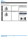
The brake levers are equipped with a mode switching mechanism which can be used to make them compatible with cantilever brakes and roller brakes
or V-BRAKE brakes with power modulator. (SB-C6000-8/SB-C3000-7 is compatible with roller brakes or V-BRAKE brakes with power modulator. Please
note that it is not compatible with cantilever brakes.)
If the incorrect mode is selected it may result in either excessive or insufficient braking force, which is highly dangerous.
Select the correct mode as shown in the illustrations.
Brake levers with mode switching mechanism can be assembled as shown in the illustrations.
Mode position Applicable brake caliper
C : Mode position for compatibility with cantilever brakes
R : Mode position for compatibility with roller brakes
C R
V
V
C R
C·R position
•
Cantilever brakes
•
Roller brakes
For SB-C6000-8/SB-C3000-7
R :
Mode position for compatibility with roller brakes
V
R
R position
•
Roller brakes
V : Mode position for compatibility with V-BRAKE brakes
with power modulator
C R
V
V
C R
V position
•
V-BRAKE brakes with power
modulator
•
Check that the wheels are fastened securely before riding the bicycle. If the wheels are loose in any way, they may come off the bicycle and serious
injury may result.

7
TO ENSURE SAFETY
For Installation to the Bicycle, and Maintenance:
•
When securing the brake arm to the frame, be sure to use a brake arm clip that matches the size of the chainstay, and securely tighten them with the
clip bolt and clip nut to the specified tightening torque.
Use a lock nut with a nylon insert (self-locking nut) as the clip nut. It is recommended that Shimano made clip bolts, clip nuts, and arm clips be used.
If the clip nut comes off the brake arm, or if the clip bolt or arm clip becomes damaged, the brake arm may rotate on the chainstay and cause the
handlebars to jerk suddenly, or the bicycle wheel may lock and the bicycle may fall over, causing serious injury.
•
When installing the hub to the frame, be sure to install the correct non-turn washers to the left and right sides, and securely tighten the hub nuts to
the specified torques. If the non-turn washers are installed on one side only, or if the hub nuts are not tightened sufficiently, the non-turn washer may
fall out, which could cause the hub axle to rotate and the cassette joint to turn, resulting in the handlebars being accidentally pulled by the shifting
cable and an extremely serious accident.
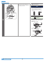
Disc brake rotor
•
Please make sure to keep your fingers away from the rotating disc brake rotor. The disc brake rotor is sharp enough
to inflict severe injury to your fingers if caught in the openings of the disc brake rotor while it is moving.
•
The calipers and disc brake rotor will become hot when the brakes are operated; do not touch them while riding or immediately after dismounting
from the bicycle. Otherwise you may get burned.
•
Be careful not to allow any oil or grease to get onto the disc brake rotor and brake pads. Otherwise the brakes may not work correctly.
•
If any oil or grease gets on the brake pads, consult a dealer or an agency. Otherwise the brakes may not work correctly.
•
If noise occurs during brake operation, the brake pads may have been worn down to the usable limit.
After checking that the temperature of the brake system has cooled down sufficiently, check that the thickness of
each pad is 0.5 mm or more. Or, consult a dealer or an agency.
2 mm 0.5 mm
•
If the disc brake rotor is cracked or deformed, immediately stop using the brakes and consult a dealer or an agency.
•
If the disc brake rotor becomes worn down to a thickness of 1.5 mm or less, or if the aluminum surface appears, immediately stop using the brakes and
consult a dealer or an agency. The disc brake rotor may break, and you may fall off the bicycle.
Coaster brake hub
•
When using a reversed fork end, use a chain adjuster to remove excess slack from the chain.

8
TO ENSURE SAFETY
CAUTION
Be sure to also inform users of the following:
•
Be sure to shift the shifting lever one gear at a time. During shifting, reduce the force being applied to the pedals. If you try to force operation of the
shifting lever or perform multi-shifting while the pedals are being turned strongly, your feet may come off the pedals and the bicycle may fall over,
which could result in serious injury.
Using the shifting lever to multi-shift to a light gear may also cause the outer casing to spring out of the shifting lever.
This does not affect the capabilities of the shifting lever because the outer casing returns to the original position after shifting.
•
If the brake is used frequently, the area around the brake may become hot. Do not touch the area around the
brake for at least 30 minutes after riding the bicycle.
Area around the brake
Coaster brake specifications
•
Continuous application of the brakes when riding down long slopes will cause the internal brake parts to become very hot, weakening braking
performance, and may also cause a reduction in the amount of brake grease inside the brake, leading to problems such as abnormally sudden braking.
•
Spin the wheel and confirm that the braking force of the coaster brake is correct.
NOTE
Be sure to also inform users of the following:
•
The gears can be shifted while lightly pedaling, but on rare occasions the pawls and ratchet inside the hub may produce some noise afterwards as part
of normal gear shifting operation. In addition, a loud sound may be temporarily emitted if the gears are shifted while strongly pedaling with E-BIKE,
etc., but this is normal.
•
The internal geared hub is not completely waterproof. Avoid using the hub in places where water might get inside and do not use high-pressure
water to clean the hub, otherwise the internal mechanism may rust.
•
Do not disassemble the hub. If you need to disassemble it, contact the place of purchase.
•
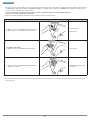
All of the following occurrences are due to the internal gear-shifting structure and are not the failure of the internal components.
Phenomenon
Type of hub
Gear positions where
phenomenon might occur
For coaster brakes
For roller brakes/
V-BRAKE
Noise occurs when the pedals rotate. × 7-speed hub All gear positions except 1st
Noise occurs when the bicycle is pushed backward. × 8-speed hub 5th, 6th, 7th, 8th
The hub has a built-in mechanism that supports gear shi
fting
and when the mechanism operates during gear shi
fting,
noise and vibrations occur.
× 8-speed hub All gear positions
Depending on gear position, gear-shifting may feel different. ×
8-speed hub, 7-speed
hub
All gear positions
Noise occurs when pedal rotation is stopped during riding. × 7-speed hub All gear positions
•
Products are not guaranteed against natural wear and deterioration from normal use and aging.
•
For maximum performance we highly recommend Shimano lubricants and maintenance products.
Coaster brake specifications
•
If the wheels are not rotating smoothly, you need to replace or grease the brake shoes. Consult the dealer where you made the purchase.

9
TO ENSURE SAFETY
For Installation to the Bicycle, and Maintenance:
•
The cassette joint should only be used with sprockets with 16T to 23T.
•
The gear ratio of the front chainring to the rear is about 2.1-to-1.
Example) For 26 inch wheels
Front 36T 38T 46T
Rear 16T 18T 22T
•
To maintain the product in good working order, it is recommended to have the place of purchase or a distributor carry out maintenance such as
lubrication of the internal parts about once a year from the first time of use (once every 2,000 km if the bicycle is used very frequently). If the bicycle is
used under harsh conditions, more frequent maintenance is required. Also, for carrying out maintenance, the use of SHIMANO internal geared hub
grease or a lubrication kit is recommended. If SHIMANO grease or a SHIMANO lubrication kit is not used, problems such as a malfunction in gear
shifting may occur.
•
If the wheel becomes stiff and difficult to turn, lubricate it with grease.
•
The gears should be periodically washed with a neutral detergent. In addition, cleaning the chain with neutral detergent and lubricating it can be an
effective way of extending the life of the gears and the chain.
•
If the chain keeps coming off the gears during use, replace the gears and chain.
Coaster brake specifications
•
Use a wheel with 3x or 4x spoke lacing. Wheels with radial lacing cannot be used. Otherwise, the spokes or the wheel may get damaged, or noise may
occur when braking.
•
If the wheel becomes stiff and difficult to turn, you should replace the brake shoes or lubricate with grease.
•
Use only the specified grease for the brake shoes and when using a lubrication kit, remove the brake shoes to avoid contact with the oil.
The actual product may differ from the illustration because this manual is intended mainly to explain the procedures for using
the product.

LIST OF TOOLS TO BE USED

11
LIST OF TOOLS TO BE USED
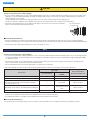
LIST OF TOOLS TO BE USED
The following tools are needed for installation, adjustment, and maintenance purposes.
Tool Tool Tool
2 mm hexagon wrench 10 mm spanner Hexalobular[#25]
3 mm hexagon wrench Screwdriver[#1] Adjustable wrench
5 mm hexagon wrench TL-LR10 TL-CJ40 (Y70898020)

INSTALLATION

13
INSTALLATION
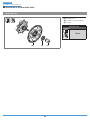
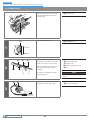
Installation of the sprocket to the hub
INSTALLATION
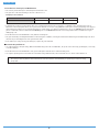
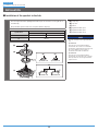
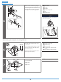
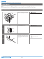
Installation of the sprocket to the hub
Place the right-hand dust cap B/right-hand dust cap C onto the driver on the right side of
the hub body.
Next, install the sprocket and secure it in place with the snap ring.
(A)
Snap ring
(B)
Sprocket
(C)
Driver
(D)
Right-hand dust cap C
(E)
Right-hand dust cap B
(F)
Right-hand dust cap A
NOTE
Note the orientation of the right-hand dust
cap.
Specification A
If the sprocket is an inward assembling
sprocket with 19T or fewer or for belt drive
specifications, right-hand dust cap A will come
into contact with the chain or pulley so
specification B should be used instead.
Specification B
If the sprocket is an inward assembling
sprocket with 16T and 3 mm teeth or for belt
drive specifications, remove right-hand dust
cap B before use.
Specifications
Applicable sprockets
Outward assembling Inward assembling
A
16T-23T
20T-23T
B
16T-23T
(A)
(B)
(C)
(F)
Specification A Specification B
Specification A Specification B
(D) (E)

14
To be continued on next page
INSTALLATION
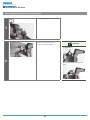
Installation of the cassette joint to the hub
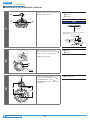
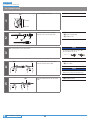
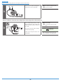
Installation of the cassette joint to the hub
1
(B)
(A)
(C)
Install the driver cap to the driver on the
right side of the hub body.
(A)
Driver cap
(B)
Driver
(C)
Sprocket
NOTE
Note the orientation of the driver cap.
Driver side
Install the driver cap in the position shown in
the illustration.
Sprocket
Snap ring
Driver cap
2
(A)
(B)
(z)
Turn the cassette joint pulley in the
direction of the arrow to align the red
marks on the pulley and the bracket.
(z)
Should be aligned
(A)
Pulley
(B)
Bracket
3
(z)
(A)
(z)
Install it with the red marks (z) on the
cassette joint aligned with the red
(SG-C6001/SG-C6011) or yellow
(SG-C3001) marks (z) on the right side of
the hub body.
(A)
Cassette joint

15
INSTALLATION
Installation of the cassette joint to the hub
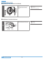
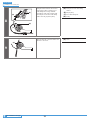
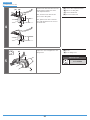
4
LOCK
(z)
(A)
(B)
Secure the cassette joint to the hub with
the cassette joint mounting ring.
When installing the cassette joint
mounting ring, align the yellow mark
(z) with the yellow mark (z) on the
pulley of the cassette joint.
(A)
Cassette joint mounting ring
(B)
Pulley
5
LOCK
(A)
Turn the cassette joint mounting ring 45°
clockwise.
(A)
Cassette joint mounting ring
NOTE
Hold down the cassette joint bracket securely
when performing work.

16
To be continued on next page
INSTALLATION
Installing the Inter-M brake to the hub body
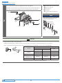
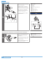
Installing the Inter-M brake to the hub body
(z)
(A) (B)(C)
Engage the hub body splines (z) with the
INTER M brake splines (z), and then
tighten with the brake unit fixing
washer.
(A)
Inter-M brake
(B)
Hub body
(C)
Brake unit fixing washer
Installation of the hub to the frame
1
(A)
(B)
Mount the chain on the sprocket, and
then set the hub axle into the fork end.
(A)
Hub axle
(B)
Fork end

17
To be continued on next page
INSTALLATION
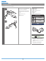
Installation of the hub to the frame
2
Place non-turn washers and onto the right and left sides of the hub axle.
At this time, turn the cassette joint so that the protrusions of the non-turn washers fit into
the grooves in the fork ends and align the joint to be almost parallel to the chainstay.
(A)
Non-turn washer (for left-side use)
(B)
Groove in fork end
(C)
Cassette joint
(D)
Chainstay
(E)
Non-turn washer (for right-side
use)
NOTE
When installing parts such as a mudguard stay
to the hub axle, install them in the order
shown in the illustration below.
Non-turn washer
Mudguard stay
Carrier stay
Washer
Cap nut
(A)
(E)
(D)(C)
(B)
TECH TIPS
•
The protrusion should be on the fork end side.
•
Install the non-turn washer so that the protrusion fits securely in the fork end groove at the front and back sides of the hub axle.
•
Use a non-turn washer that matches the shape of the fork end. Different non-turn washers are used for the left and right sides.
Fork end
Non-turn washer
Mark/Color
Size
For right For left
Standard
5R/Yellow 5L/Brown ϴ ≤20°
7R/Black 7L/Gray 20°≤ ϴ ≤38°
Reversed 6R/Silver 6L/White ϴ =0°
Reversed
(Full chain case)
5R/Yellow 5L/Brown ϴ
=0°
Vertical 8R/Blue 8L/Green ϴ =60° - 90°
Note: Vertical type does not include the coaster specifications
θ
Mark

18
To be continued on next page
INSTALLATION
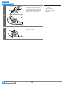
Installation of the hub to the frame
In the case of Inter-M brake specifications
2
(A)
(B)
(C)
(D)
Attach the brake arm of the Inter-M
brake to the chainstay with the brake
arm clip.
Next, temporarily fix the clip bolt and
clip nut by lightly tightening them.
(A)
Brake fixing washer
(insert manually)
(B)
Clip nut
(C)
Arm clip
(D)
Clip bolt (M6 × 16 mm)
NOTE
Check that the brake unit is firmly secured to
the hub with the brake unit fixing washer.
TECH TIPS
If the hub nuts are cap nuts, use a frame with
fork ends that are at least 7 mm thick.
3
(A)
Take up slack in the chain and secure the
wheel to the frame with the cap nut.
(A)
Hub nut
Tightening torque
30 - 45 N·m
NOTE
Check that the wheel is fixed securely to the
frame with the hub nut.

19
INSTALLATION
Installation of the hub to the frame
4
Fix the brake arm securely to the chainstay with the arm clip.
Check that the brake arm is securely fastened to the chainstay with the brake arm clip.
(A)
Arm clip
(B)
Chainstay
(C)
Brake arm
(D)
Clip nut
(E)
Clip bolt (M6 × 16 mm)
Tightening torque
2 - 3 N·m
WARNING
•
When securing the brake arm to the frame,
be sure to use a brake arm clip that
matches the size of the chainstay, and
securely tighten them with the clip bolt
and clip nut to the specified tightening
torque.
•
Use a lock nut with a nylon insert
(self-locking nut) as the clip nut.
•
It is recommended that Shimano made clip
bolts, clip nuts, and arm clips be used.
•
If the clip nut comes off the brake arm, or
if the clip bolt or arm clip becomes
damaged, the brake arm may rotate on the
chainstay and cause the handlebars to jerk
suddenly, or the bicycle wheel may lock
and the bicycle may fall over, causing
serious injury.
NOTE
•
If it is not installed correctly, braking
performance will suffer. Be careful not to
apply excessive force when installing.
•
If excessive force is applied to the brake
arm to secure it, the wheel will make noise
and become difficult to turn.
•
After installing the arm clip, check that the
clip bolt protrudes about 2 to 3 mm from
the end face of the clip nut.
Clip nut
Brake arm
Arm clip
Clip bolt
(M6 × 16 mm)
2 - 3 mm
•
Before using the Coaster Brake, check that
the brake works properly and that the
wheel turns smoothly.
(A)(B)
(C)
In the case of coaster brake specifications
(D)(C) (E)
(A)(B)

20
INSTALLATION
Installation of the disc brake rotor
Installation of the disc brake rotor
Center lock type
(A) (B) (C)
(A)
Disc brake rotor
(B)
Disc brake rotor fixing lock ring
(C)
TL-LR10
Tightening torque
40 N·m
Page is loading ...
Page is loading ...
Page is loading ...
Page is loading ...
Page is loading ...
Page is loading ...
Page is loading ...
Page is loading ...
Page is loading ...
Page is loading ...
Page is loading ...
Page is loading ...
Page is loading ...
Page is loading ...
Page is loading ...
Page is loading ...
Page is loading ...
Page is loading ...
Page is loading ...
Page is loading ...
Page is loading ...
Page is loading ...
Page is loading ...
Page is loading ...
Page is loading ...
Page is loading ...
Page is loading ...
Page is loading ...
-
 1
1
-
 2
2
-
 3
3
-
 4
4
-
 5
5
-
 6
6
-
 7
7
-
 8
8
-
 9
9
-
 10
10
-
 11
11
-
 12
12
-
 13
13
-
 14
14
-
 15
15
-
 16
16
-
 17
17
-
 18
18
-
 19
19
-
 20
20
-
 21
21
-
 22
22
-
 23
23
-
 24
24
-
 25
25
-
 26
26
-
 27
27
-
 28
28
-
 29
29
-
 30
30
-
 31
31
-
 32
32
-
 33
33
-
 34
34
-
 35
35
-
 36
36
-
 37
37
-
 38
38
-
 39
39
-
 40
40
-
 41
41
-
 42
42
-
 43
43
-
 44
44
-
 45
45
-
 46
46
-
 47
47
-
 48
48


Ask a question and I''ll find the answer in the document
Finding information in a document is now easier with AI
Related papers
-
Shimano CJ-NX40 Service Instructions
-
-
Shimano CJ-8S40 Technical Service Instruction
-
-
Shimano SG-3C41 Service Instructions
-
Shimano SL-8S31 User manual
-
Shimano SL-C7000-5 User manual
-
Shimano SB-C3000-7 User manual
-
Shimano ST-8S20 Service Instructions
-
Shimano SG-S7051-11 User manual
Other documents
-
König KN-PVA10 Datasheet
-
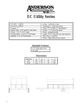 Anderson Manufacturing EC Utility Series User manual
-
Global Industrial 293224 User manual
-
Apollo 2009 Owner's manual
-
-
-
Nexus SW-NX30 Service Instructions
-
Autonics SFDL-SDK Series Quick start guide
-
 Chainway User manual
-
sks BLUEMELS User manual

