Page is loading ...

4-408-371-11 (1)
© 2011 Sony Corporation
Solid-State Memory
3D Camcorder
Operating Instructions
Before operating the unit, please read this manual thoroughly
and retain it for future reference.
PMW-TD300

2
Important Safety Instructions
• Read these instructions.
• Keep these instructions.
• Heed all warnings.
• Follow all instructions.
• Do not use this apparatus near water.
• Clean only with dry cloth.
• Do not block any ventilation openings.
Install in accordance with the
manufacturer’s instructions.
• Do not install near any heat sources such
as radiators, heat registers, stoves, or
other apparatus (including amplifiers) that
produce heat.
• Do not defeat the safety purpose of the
polarized or grounding-type plug. A
polarized plug has two blades with one
wider than the other. A grounding-type
plug has two blades and a third grounding
prong. The wide blade or the third prong
are provided for your safety. If the
provided plug does not fit into your outlet,
consult an electrician for replacement of
the obsolete outlet.
• Protect the power cord from being walked
on or pinched particularly at plugs,
convenience receptacles, and the point
where they exit from the apparatus.
• Only use attachments/accessories
specified by the manufacturer.
• Use only with the cart, stand, tripod,
bracket, or table specified by the
manufacturer, or sold with the apparatus.
When a cart is used, use caution when
moving the cart/apparatus combination to
avoid injury from tip-over.
• Unplug this apparatus during lightning
storms or when unused for long periods of
time.
• Refer all servicing to qualified service
personnel. Servicing is required when the
apparatus has been damaged in any way,
such as power-supply cord or plug is
damaged, liquid has been spilled or
objects have fallen into the apparatus, the
apparatus has been exposed to rain or
moisture, does not operate normally, or
has been dropped.
To reduce the risk of fire or
electric shock, do not
expose this apparatus to
rain or moisture.
To avoid electrical shock,
do not open the cabinet.
Refer servicing to qualified
personnel only.
CAUTION
Danger of explosion if battery is incorrectly
replaced.
Replace only with the same or equivalent
type recommended by the manufacturer.
When you dispose of the battery, you must
obey the law in the relative area or country.
When installing the installation space must
be secured in consideration of the ventilation
and service operation.
• Do not block the ventilation slots at the left
side and right side panels, and vents of
the fans.
• Leave a space around the unit for
ventilation.
• Leave more than 40 cm of space in the
rear of the unit to secure the operation
area.
When the unit is installed on the desk or the
like, leave at least 4 cm of space in the left
and right sides. Leaving 40 cm or more of
space above the unit is recommended for
service operation.
CAUTION
The apparatus shall not be exposed to
dripping or splashing. No objects filled with
liquids, such as vases, shall be placed on the
apparatus.
WARNING
Excessive sound pressure from earphones
and headphones can cause hearing loss.
WARNING

3
In order to use this product safely, avoid
prolonged listening at excessive sound
pressure levels.
Batteries shall not be exposed to excessive
heat such as sunshine, fire or the like.
For the customers in the U.S.A.
This equipment has been tested and found
to comply with the limits for a Class A digital
device, pursuant to Part 15 of the FCC
Rules. These limits are designed to provide
reasonable protection against harmful
interference when the equipment is operated
in a commercial environment. This
equipment generates, uses, and can radiate
radio frequency energy and, if not installed
and used in accordance with the instruction
manual, may cause harmful interference to
radio communications. Operation of this
equipment in a residential area is likely to
cause harmful interference in which case the
user will be required to correct the
interference at his own expense.
You are cautioned that any changes or
modifications not expressly approved in this
manual could void your authority to operate
this equipment.
All interface cables used to connect
peripherals must be shielded in order to
comply with the limits for a digital device
pursuant to Subpart B of Part 15 of FCC
Rules.
This device complies with Part 15 of the FCC
Rules. Operation is subject to the following
two conditions: (1) this device may not cause
harmful interference, and (2) this device
must accept any interference received,
including interference that may cause
undesired operation.
For the customers in Canada
This Class A digital apparatus complies with
Canadian ICES-003.
For the customers in Europe
This product with the CE marking complies
with the EMC Directive issued by the
Commission of the European Community.
Compliance with this directive implies
conformity to the following European
standards:
• EN55103-1: Electromagnetic Interference
(Emission)
• EN55103-2: Electromagnetic
Susceptibility (Immunity)
This product is intended for use in the
following Electromagnetic Environments: E1
(residential), E2 (commercial and light
industrial), E3 (urban outdoors), E4
(controlled EMC environment, ex. TV
studio).
The manufacturer of this product is Sony
Corporation, 1-7-1 Konan, Minato-ku,
Tokyo, Japan.
The Authorized Representative for EMC and
product safety is Sony Deutschland GmbH,
Hedelfinger Strasse 61, 70327 Stuttgart,
Germany. For any service or guarantee
matters please refer to the addresses given
in separate service or guarantee documents.
For the State of California, USA only
Perchlorate Material - special handling may
apply, See
www.dtsc.ca.gov/hazardouswaste/
perchlorate
Perchlorate Material : Lithium battery
contains perchlorate.
For the customers in Taiwan only

Table of Contents
4
Foreword .................................................................................................... 10
Before Use....................................................................................... 10
Chapter 1 : Overview
Features ...................................................................................................... 11
3D Images ................................................................................................... 13
Using the Software..................................................................................... 17
Reading the CD-ROM Manuals............................................................... 17
Locations and Functions of Parts and Controls...................................... 18
Power Supply .................................................................................. 18
Accessory Attachments................................................................... 19
Operating and Connectors Section.................................................. 20
Monochrome LCD Panel ................................................................ 31
Viewfinder....................................................................................... 32
Viewfinder Screen Display........................................................................ 33
Chapter 2 : Preparations
Preparing a Power Supply ........................................................................ 37
Using a Battery Pack....................................................................... 37
Using AC Power ............................................................................. 38
Attaching the Viewfinder .......................................................................... 38
Attaching the Supplied Viewfinder................................................. 38
Adjusting the Viewfinder Position.................................................. 39
Adjusting the Viewfinder Angle..................................................... 39
Lifting Up the Viewfinder Barrel and Eyepiece ............................. 39
Adjusting the Viewfinder Focus and Screen................................... 41
Using the BKW-401 Viewfinder Rotation Bracket ........................ 41
Attaching a CBK-VF01 Viewfinder ............................................... 42
Attaching a 5-inch Electronic Viewfinder ...................................... 43
Setting the Area of Use.............................................................................. 44
Setting the Date/Time of the Internal Clock ........................................... 45
Preparing the Audio Input System .......................................................... 45
Connecting a Microphone to the MIC IN Connector...................... 45
Connecting Microphones to the AUDIO IN Connectors................ 46
Table of Contents

Table of Contents
5
Attaching a UHF Portable Tuner (for a UHF Wireless Microphone
System) ..................................................................................... 47
Tripod Mounting ....................................................................................... 48
Connecting a Video Light ......................................................................... 49
Using the Shoulder Strap .......................................................................... 49
Adjusting the Shoulder Pad Position ....................................................... 50
Chapter 3 : Adjustments and Settings
Setting the Video Format .......................................................................... 51
Changing the Video Format............................................................ 52
Selecting 3D or 2D Mode........................................................................... 52
Selecting 3D or 2D.......................................................................... 52
Adjusting the Black Balance and the White Balance............................. 53
Adjusting the Black Balance........................................................... 53
Adjusting the White Balance .......................................................... 54
Setting the Electronic Shutter................................................................... 56
Shutter Modes ................................................................................. 56
Selecting the Shutter Mode and Shutter Speed............................... 56
Adjusting the Iris ....................................................................................... 58
Changing the Adjustment Mode ..................................................... 58
Adjusting the Iris using the IRIS Dial............................................. 58
Adjusting the Iris using Automatic Iris Adjustment ....................... 58
Changing the Reference Value for Automatic Iris Adjustment...... 58
Zooming ...................................................................................................... 59
Using the ZOOM Dial..................................................................... 59
Using the Zoom Lever .................................................................... 59
Adjusting the Focus ................................................................................... 60
Adjusting in MF Mode.................................................................... 60
Adjusting in AF Mode .................................................................... 61
Adjusting the Convergence....................................................................... 61
Adjusting using the CONVERGENCE Dial................................... 61
Adjusting using the AUTO CONVERGENCE Button................... 62
Adjusting using the Assignable Switches ....................................... 62
Changing the Viewfinder Display ............................................................ 62
Adjusting the Audio Level ........................................................................ 63
Manually Adjusting the Audio Levels of the Audio Inputs from the
AUDIO IN CH-1/CH-2 Connectors ......................................... 63
Manually Adjusting the Audio Level of the MIC IN Connector.... 63
Recording Audio on Channels 3 and 4 ........................................... 64

Table of Contents
6
Setting the Time Data................................................................................ 65
Setting the Timecode....................................................................... 65
Setting the User Bits........................................................................ 66
Synchronizing the Timecode........................................................... 66
Checking Camcorder Settings and Status Information
(Status Screens).................................................................................... 68
Chapter 4 : Shooting
Handling SxS Memory Cards................................................................... 70
About SxS Memory Cards .............................................................. 70
Loading and Ejecting SxS Memory Cards...................................... 71
Selecting the SxS Memory Card to Use.......................................... 72
Formatting (Initializing) SxS Memory Cards ................................. 73
Checking the Remaining Recording Time...................................... 73
Restoring SxS Memory Cards......................................................... 74
Basic Operations ........................................................................................ 75
Playing Recorded Clips................................................................... 76
Deleting Recorded Clips ................................................................. 77
Advanced Operations ................................................................................ 77
Recording Shot Marks..................................................................... 77
Setting OK Marks ........................................................................... 77
Starting to Record from Pre-stored Video (Picture Cache Function)
(2D mode only)......................................................................... 78
Recording Time-lapse Video (Interval Rec Function).................... 79
Shooting Stop Motion Animations (Frame Rec Function) ............. 80
Shooting with Slow & Quick Motion ............................................. 82
Framing Shots with the Freeze Mix Function................................. 83
Planning Metadata Operations ................................................................ 84
Loading a Planning Metadata File into Camcorder’s
Internal Memory ....................................................................... 84
Defining Clip Names in Planning Metadata ................................... 85
Defining Shot Mark Names in Planning Metadata ......................... 86
3D Shooting Guide Function..................................................................... 87
Displaying the Subject Distance Range .......................................... 87
Displaying 3D Depth Warning........................................................ 87
Displaying the Grid......................................................................... 88

Table of Contents
7
Chapter 5 : Clip Operations
Clip Playback ............................................................................................. 89
Thumbnail Screen ........................................................................... 89
Playing Clips ................................................................................... 91
Using Thumbnails to Search Inside Clips....................................... 92
Thumbnail Operations .............................................................................. 93
THUMBNAIL Menu Configuration............................................... 93
Basic THUMBNAIL Menu Operations.......................................... 94
Changing the Thumbnail Screen Type............................................ 94
Displaying Clip Properties .............................................................. 95
Adding and Deleting OK Marks ..................................................... 96
Copying Clips ................................................................................. 96
Deleting Clips.................................................................................. 97
Displaying the Expand Thumbnail Screen...................................... 98
Displaying the Shot Mark Thumbnail Screen................................. 98
Adding and Deleting Shot Marks.................................................... 99
Changing Clip Index Pictures ......................................................... 99
Chapter 6 : Menu and Detailed Settings
Setup Menu Organization and Levels.................................................... 100
Setup Menu Organization ............................................................. 100
Setup Menu Levels........................................................................ 100
Basic Setup Menu Operations ................................................................ 101
Menu List.................................................................................................. 104
OPERATION Menu...................................................................... 104
PAINT Menu................................................................................. 122
MAINTENANCE Menu ............................................................... 127
FILE Menu.................................................................................... 140
Assigning Functions to Assignable Switches ......................................... 142
Functions that can be Assigned to the ASSIGN. 0 Switch ........... 142
Functions that can be Assigned to the ASSIGN. 2 Switch ........... 143
Functions that can be Assigned to the ASSIGN. 1 and 3 Switches,
the ASSIGNABLE 4 and 5 Switches, and the COLOR TEMP.
Button...................................................................................... 143
Functions that can be Assigned to the ASSIGN. 6 Switch ........... 145
Functions that can be Assigned to the RET Button ...................... 145
Assigning Functions to the Lens Dials ................................................... 146
Functions that can be Assigned to the Lens Dials......................... 146

Table of Contents
8
Chapter 7 : Saving and Loading User Setting Data
Saving and Loading Settings................................................................... 147
Saving Setting Data....................................................................... 147
Loading Setting Data..................................................................... 148
Resetting a File after Changing Its Contents................................. 148
Saving and Loading Scene Files ............................................................. 149
Saving Scene Files ........................................................................ 149
Loading Scene Files ...................................................................... 149
Chapter 8 : Connecting External Devices
Connecting External Monitors ............................................................... 151
Operating Clips with a Computer.......................................................... 153
Using the ExpressCard Slot of a Computer .................................. 153
USB Connection with a Computer................................................ 153
Editing 3D Clips using MPES-3D01 ...................................................... 155
Chapter 9 : Maintenance
Testing the Camcorder............................................................................ 156
Maintenance ............................................................................................. 156
Cleaning the Viewfinder ............................................................... 156
Note about the Battery Terminal................................................... 156
Adjusting Left/Right Lens Errors.......................................................... 157
Correcting at a Single Point .......................................................... 157
Correcting at Multiple Points........................................................ 157
Adjusting the Flange Focal Length............................................... 158
Operation Warnings................................................................................ 159
Error Indication............................................................................. 159
Warning Indication........................................................................ 160
Appendix
Important Notes on Operation ............................................................... 166
Exchanging the Battery of the Internal Clock ...................................... 168
Specifications............................................................................................ 169
General.......................................................................................... 169
Camera Block................................................................................ 169
Audio Block .................................................................................. 170

Table of Contents
9
Display .......................................................................................... 170
Media Block.................................................................................. 170
Inputs/Outputs............................................................................... 170
Lens Block .................................................................................... 171
Supplied Accessories .................................................................... 171
Recommended Additional Equipment .......................................... 171
Chart of Optional Components and Accessories .................................. 173
MPEG-2 Video Patent Portfolio License............................................... 174
About Bitmap Fonts ................................................................................ 174
About OpenSSL ....................................................................................... 175
Index.......................................................................................................... 178

Foreword
10
After purchasing the PMW-TD300 Solid-State
Memory 3D Camcorder, before operating, it is
necessary to set the area of use.
(Unless this setting is made, the camcorder will
not operate.)
For details of these settings, see “Setting the Area of
Use” (page 44).
Note
Before attaching/removing optional components or
accessories to/from the PMW-TD300 (referred to as “the
camcorder”), be sure to turn the power of the camcorder
off.
Viewing 3D Video
• Viewing 3D video shot using this camcorder on
a 3D monitor can cause symptoms of
discomfort, such as eye fatigue, tiredness, or
nausea. It is recommended that you take regular
rest breaks when watching 3D video. The
duration and frequency of required rest breaks
will vary from person to person, so each person
must judge for themselves. If discomfort
occurs, stop watching 3D video until the
symptoms subside, and consult your doctor if
necessary. Also, please follow the instructions
provided with the software or the hardware
connected to the camcorder. Furthermore, the
sense of vision of young children (especially
children less than 6 years of age) is still in a
development stage. Before allowing young
children to view 3D video, please consult a
pediatrician or ophthalmologist. A responsible
adult should always supervise any children to
observe the above-mentioned precautions.
• The perception of 3D video varies depending on
the individual.
Foreword
Before Use

Features
11
Chapter 1 Overview
The camcorder is a shoulder-mount HD memory
camcorder featuring independent Left/Right,
1
/
2
-
type (diagonal 8 mm (
11
/
32
inches)), full-HD
(1920 × 1080) “Exmor” 3CMOS image sensors.
Dual, fixed lens system
Employs a dual, fixed-type lens that requires no
Left/Right-lens optical axis, angle of view, or
image quality adjustments, so you can start
shooting straight away.
Convergence control
The all-important convergence point can be
adjusted between approximately 1.2 m (lens
surface reference) and infinity for 3D image
representation. When shooting, you can align the
convergence point with the focus position using
one-button control.
Also, the inter-axial distance is a fixed 45 mm,
allowing wide-scope 3D images to be captured.
Unique triple dial operation
The camcorder employs a unique triple dial for
adjusting zoom, iris, and convergence, and which
synchronizes the operation of both the left and
right lens.
The function assigned to each dial can also be
customized.
3D shooting guide function
This displays a guide in the viewfinder of the
appropriate distance to the subject in order to
avoid viewer discomfort due to the parallax
between the left and right lens becoming too
large. It can also display a warning if the parallax
at the subject becomes too large. These allow the
shooting of more natural 3D images that can be
viewed comfortably.
Also, you can view 3D images in the viewfinder
using the naked eye, and the camcorder supports
various display formats for checking anaglyph
and other parallax.
3D image output to external devices
It is equipped with dual HD-SDI outputs, and can
output individual Left/Right image signals.
Furthermore, one output also supports 3G-SDI
for output of both left and right image signals
paired together.
3D images can also be output in side-by-side
format from HDMI and HD-SDI connectors.
SxS memory cards as recording media
The camcorder employs the high-performance
SxS memory cards used in XDCAM EX-series
equipment as the storage media. The left and right
images are synchronized and recorded onto two
SxS memory cards. There are four memory card
slots, two each on both the left and right, allowing
recording across two memory cards.
Approximately 6 hours of 3D images can be
recorded when loaded with four 64 GB SxS
memory cards.
Light weight, low power consumption
Design features such as CMOS image sensors,
custom video signal processing ICs, and SxS
memory card recording enable operation at power
consumption of 32 W or less. The camcorder’s
light weight (5.5 kg (12 lb 2 oz)) and low center
of gravity make it easy to carry on the shoulder
while ensuring superior stability.
HD recording using the “MPEG-2 Long
GOP” codec
The camcorder records 1920 × 1080, 1440 ×
1080, and 1280 × 720 HD images using “MPEG-
2 Long GOP” codec compression. It offers a
choice of bit rates: either 35 Mbps (HQ mode) or
25 Mbps (SP mode).
By utilizing an efficient compression format, the
camcorder records high-quality HD images for
long recording time of approx. 200 minutes at
Chapter1 Overview
Features

Features
12
Chapter 1 Overview
35 Mbps (HQ mode) or approx. 280 minutes at
25 Mbps (SP mode) on a single 64-GB SxS
memory card.
Multi-format support
The camcorder supports interlace format
recording (1080/59.94i or 1080/50i), progressive
format recording (1080/29.97P, 1080/23.98P,
720/59.94P, 720/29.97P, 720/23.98P, or 1080/
25P, 720/50P, 720/25P), thus offering the
flexibility needed for worldwide HD recording.
(For 23.98P, native frequency recording is
possible.)
It also can output HD signals down-converted to
SD.
A variety of functions for improved
performance under various shooting
conditions
• Optical ND filters and electrical CC filters
• Hyper gamma
• Slow shutter function
• Frame Recording function
• Time lapse function (interval recording)
• Slow & quick motion function
• Freeze mix function
• Focus magnification function
• Assignable switches
• 3.5-inch high-resolution color LCD viewfinder
• Remote control
• 2D shooting mode
Wireless LAN support
You can connect this camcorder to a computer
over a wireless LAN (Wi-Fi connection) by
connecting the optional CBK-WA01 Wi-Fi
Adapter to the external device connector.
A Wi-Fi connection allows you to transfer
planning metadata from a computer to this
camcorder, and to transfer clips and other files
from this camcorder to a computer. You can also
use the Live Logging function to transfer proxy
AV data to a computer as you shoot, for logging
of the video currently being shot.
Inherits unique features of XDCAM EX
series
The camcorder inherits the workflow features of
the XDCAM EX series, including thumbnail
display and metadata management, and improves
them by introducing an improved man-machine
interface.
XDCAM EX web sites
For information on XDCAM EX, visit the
following web sites:
United States
http://www.sony.com/xdcamex
Canada
http://www.sony.ca/xdcamex
Europe, Middle East, Africa, and Russia
http://www.sonybiz.net/xdcamex
Latin America
http://www.sonypro-latin.com/xdcamex
Australia
http://www.sony.com.au/xdcamex
Asia (except Korea, China, and Japan)
http://pro.sony-asia.com
Korea
http://bp.sony.co.kr/xdcamex
China
http://pro.sony.com.cn/minisite/XDCAMEX
Japan
http://www.sony.co.jp/XDCAMEX

3D Images
13
Chapter 1 Overview
When people look at objects, the left eye and right eye view the object at a slightly different angle, and
hence the images projected in the left and right eye are different. The difference in images seen by the left
and right eye is called parallax.
By composing a picture in the head from the left and right eye images, people gain an awareness of depth
and stereoscopic effect.
3D images utilize this technique to display subjects in three dimensions. When shooting 3D images, lenses
substitute for the left eye and right eye to shoot subjects at a slightly different angle.
During playback, the right lens image is viewed by the right eye only and likewise for the left lens image,
and hence a three-dimensional subject is recognized in the minds of the viewers.
3D Images
Left eye image Right eye image
Subject recognition

3D Images
14
Chapter 1 Overview
Convergence Point
When shooting using individual left and right lenses, the point where the optical axes of the left lens and
right lens intersect is called the convergence point. The difference (parallax) between left and right images
for subjects at the convergence point is zero. During playback, subjects at the convergence point appear
to viewers to be positioned right on the screen. Subjects in front of the convergence point appear to pop
out of the screen, while subjects behind the convergence point appear to recede into the distance.
Accordingly, it is essential to set the convergence point appropriately when shooting in order to effectively
create the popping out and receding sensation during playback.
The camcorder convergence point can be adjusted in the range 1.2 m (4 ft) to ∞ (infinity). You can set the
convergence point to the focus position using a single button push, store multiple convergence points, and
recall convergence points when shooting. (see page 61)
Comfortable 3D Images
For subjects displaced from the convergence point, the parallax becomes larger as the distance from the
convergence point becomes larger. In other words, the closer the subject the more it will appear to pop
out, and the further away the more it will appear to recede into the distance. If the parallax becomes too
large, it becomes difficult for the viewer to combine the left and right images, and not only will the 3D
image appear unnatural but it may also cause eye fatigue and discomfort while viewing. Therefore, in
order to shoot comfortable 3D images for the viewer, it is essential to keep the size of parallax within an
appropriate range.

3D Images
15
Chapter 1 Overview
Parallax Guidelines
To shoot comfortable 3D images, we recommend the following points as parallax guidelines.
Parallax angle should be less than 1°
The parallax angle (
θ
) is obtained by subtracting the angle (
α
or
β
) between the left/right lenses at the
subject position from the angle (
γ
) between the left/right lenses at the convergence point, where the
optical axes of the left/right lenses intersect. The parallax angle is negative for subjects that appear to pop
out of the screen, and positive for subjects that appear to recede into the distance. The parallax angle for
comfortable 3D images is less than ±1°.
Since measuring the parallax angle is difficult when shooting, it is common to display an overlay of the
left and right images on a screen and check the size of the image mismatch (amount of parallax). When
images are viewed from a distance approximately 3 times the height of the screen, the amount of parallax
on the screen due to a parallax angle of 1° is roughly 3% of the screen width. When shooting, this guideline
translates into keeping the amount of parallax within 3% of the viewfinder screen width in order to
produce natural stereoscopic images.
Amount of parallax on the screen should not exceed space between eyes
When the amount of parallax on the screen exceeds the distance between the eyes of the viewer, it
becomes impossible to form the left and right images into a single image, making the viewer feel
discomfort. Since the space between the eyes is an individual trait, a rule of thumb is to keep amount of
parallax on the screen to less than 5 cm (2 inches). If the screen is small (77-inch type or smaller),
maintaining a parallax angle of less than 1° ensures that the amount of parallax cannot exceed 5 cm
(2 inches). However, if the screen is large (77-inch type or larger), the amount of parallax on the screen
becomes larger as the screen becomes larger, and it becomes easy to exceed the 5 cm (2 inches) guideline.
Consequently, it is important to consider the screen size when shooting.
α
Parallax angle
θ
=
γ
–
α
(or
β
)
Amount of parallax
Convergence point

3D Images
16
Chapter 1 Overview
The camcorder displays the subject distance from the camera in the viewfinder as an aid to keeping the
parallax within an appropriate range. The viewfinder can also display a colored outline of the subject as a
warning when the parallax is large and natural stereoscopic vision of the subject is difficult. You can set
the amount of parallax as a percentage of the screen width (near field, far field) or you can specify the
maximum screen size as the reference for displaying the guide functions. (see page 87)

Using the Software / Reading the CD-ROM Manuals
17
Chapter 1 Overview
The supplied CD-ROM (labeled “Utility
Software for XDCAM”) contains application and
device driver software required to access to SxS
memory cards from a computer and to manage
material shot with the camcorder.
Information about how to install the software is
provided in PDF format.
Note
You must install the SxS device driver on your computer
if your computer is equipped with an ExpressCard slot
and you want to use it to access SxS memory cards.
Preparations
The following program must be installed on your
computer in order to read the documents
contained on the CD-ROM.
Adobe Reader Version 6.0 or higher
Memo
If Adobe Reader is not installed, you can download it
from the following URL:
http://www.adobe.com/
Adobe and Adobe Reader are trademarks of Adobe
Systems Incorporated in the United States and/or other
countries.
To read the documents
Do the following:
1 Insert the CD-ROM in your CD-ROM
drive.
A cover page appears automatically in your
browser.
If it does not appear automatically in the
browser, double-click on the index.htm file
on the CD-ROM.
2 Select and click on the manual that you
wish to read.
This opens the PDF file.
Memo
The files may not be displayed properly, depending on
the version of Adobe Reader. In such a case, install the
latest version you can download from the URL
mentioned in “Preparations” above.
Note
If you have lost or damaged the CD-ROM, you can
purchase a new one to replace it. Contact a Sony service
representative.
Using the Software Reading the CD-ROM
Manuals

Locations and Functions of Parts and Controls
18
Chapter 1 Overview
a LIGHT switch
Determines how a video light connected to the
LIGHT connector (see page 19) is turned on and
off.
AUTO: When the POWER switch of the video
light is in the on position, the video light is
turned on automatically while the camcorder
is recording.
MANUAL: You can turn the video light on or off
manually, using its own switch.
Note
When the camcorder is set for recording in Picture Cache
mode, it is not possible to turn on the light before
operation to start recording is carried out (or while data
is being stored in memory).
b POWER switch
Turns the main power supply on and off.
c DC IN (DC power input) connector
(XLR type, 4-pin, male)
To operate the camcorder from an AC power
supply, connect an optional DC power cord to this
terminal and then connect the cord to the DC
output terminal of the BC-L70, BC-L160, or
another battery charger.
d DC OUT 12 V (DC power output)
connector (4-pin, female)
Supplies power for an optional WRR-860C/861/
862 UHF Synthesized Diversity Tuner
(maximum 0.5 A).
Note
Do not connect any equipment other than the UHF
synthesized diversity tuner.
e Battery attachment shoe
Attach a BP-GL95A/L80S/L60S Battery Pack.
Alternatively, you can attach an AC-DN2B/
DN10 AC Adaptor to operate the camcorder on
AC power supply.
For details, see “Preparing a Power Supply”
(page 37).
For details, see “Attaching a UHF Portable Tuner
(for a UHF Wireless Microphone System)”
(page 47).
Note
For your safety, and to ensure proper operation of the
camcorder, Sony recommends the use of the following
battery packs: BP-GL95A, BP-L60S, and BP-L80S.
Locations and Functions
of Parts and Controls
Power Supply

Locations and Functions of Parts and Controls
19
Chapter 1 Overview
a Shoulder strap fitting
Attach the supplied shoulder strap (see page 49).
b Accessory fitting shoe
Attach an optional accessory such as a video light
(see page 49).
c Viewfinder front-to-back positioning
lever
To adjust the viewfinder position in the front-to-
back direction, loosen this lever and the LOCK
knob. After adjustment, retighten this lever and
the LOCK knob.
d Viewfinder left-to-right positioning ring
Loosen this ring to adjust the left-to-right position
of the viewfinder (see page 39).
e Viewfinder fitting shoe
Attach the viewfinder.
f VF (viewfinder) connector (26-pin,
rectangular)
Connect the cable of the supplied viewfinder or
optional CBK-VF01 viewfinder.
g VF (viewfinder) connector (20-pin,
round)
Connect the cable of the optional DXF-series
viewfinder.
For connecting the DXF-series devices, optional
parts are required. Consult a Sony service
representative for information about connecting the
DXF-51 or DXF-C50W.
h Viewfinder front-to-back positioning
knob (LOCK knob)
Loosen this knob to adjust the front-to-back
position of the viewfinder (see page 39).
i Fitting for optional microphone holder
Fit an optional CAC-12 Microphone Holder (see
page 46).
j Shoulder pad
Raise the shoulder pad fixing lever to adjust the
position in the front-to-rear direction. Adjust the
position for maximum convenience when
operating the camcorder on your shoulder (see
page 50).
k LIGHT (video light) connector (2-pin,
female)
A video light with a maximum power
consumption of 50 W, such as the Anton Bauer
Ultralight 2 or equivalent can be connected (see
page 49).
l MIC IN (microphone input) (+48 V)
connector (XLR type, 5-pin, female)
Connect a stereo microphone to this connector.
The power (+48 V) is supplied via this connector.
m Tripod mount
When using the camcorder on a tripod, attach the
tripod adaptor (optional).
Accessory Attachments

Locations and Functions of Parts and Controls
20
Chapter 1 Overview
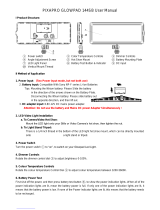
Lens Block (left side)
a VTR button
Use this to start and stop recording. Press once to
start recording, then press once more to stop.
b RET (return video) button
You can use this as an assignable switch (see
page 145).
Use this to check the video when Lens RET is
assigned to this button (factory default setting). If
you press this during recording pause, the last few
seconds recorded appear on the viewfinder screen
(recording review) (see page 75).
Pressing this button (single click) during
recording or playback records a Shot Mark 1
mark, and double-clicking records a Shot Mark 2
mark (see page 77).
c EXPAND FOCUS button
When the viewfinder display setting is L, R, or
3D, the displayed image expands, making
focusing easier (Expand Focus function).
Press the button again to return to the previous
display.
d Zoom lever
Press the W end for wide-angle and the T end for
telephoto.
Press the lever harder for a faster zoom action.
e IRIS switch
AUTO: The iris is adjusted automatically.
MANU (maual): Adjust the iris with the IRIS
dial.
f PUSH AUTO button
When the IRIS switch is in the MANU position,
press this button for an instantaneous auto
adjustment. The iris is automatically adjusted
while the button is held down.
g REMOTE FOCUS connector
Connects to an optional focus demand for focus
remote control operation.
h REMOTE ZOOM connector
Connects to an optional zoom demand for zoom
remote control operation.
i REMOTE CONVERGENCE
connector
Connects to an optional convergence demand for
convergence remote control operation.
Operating and Connectors Section
/