Page is loading ...

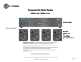
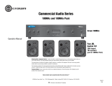
COMMERCIAL MIXER-AMPLIFIER
MODEL:
PR-130BT / PR-240BT
Specificaons are subject to change without noce

– 2 –
IMPORTANT SAFETY INSTRUCTIONS
1. Read these instructions - All the safety and operating instructions should be
read before this product is operated.
2. Keep these instructions – The safety and operating instructions should be
retained for future reference.
3. Heed all warnings – All warnings on the appliance and in the operating
instructions should be adhered to.
4. Follow all instructions – All operating and use instructions should be
followed.
5. Do not use this apparatus near water – The appliance should not be used
near water or moisture – for example, in a wet basement or near a
swimming pool, and the like.
6. Clean only with a dry cloth.
7. Do not block any ventilation openings. Install in accordance with the
manufacturer’s instructions.
8. Do not install near any heat sources such as radiators, heat registers,
stoves, or other apparatus (including amplifiers) that produces heat, without
proper ventilation.
9. Do not defeat the safety purpose of the polarized, or grounding plug. A
polarized plug has two blades with one wider than the other. A grounding
plug has two blades and a third grounding prong. The wide blade or the
third prong is provided for your safety. If the provided plug doesn’t fit into
your outlet, consult an electrician for replacement of the obsolete outlet.
10. Protect the power cord from being walked on or pinched particularly at
plugs, convenience receptacles, and at the point where they exit from the
apparatus
11. Only use attachments/accessories specified by the manufacturer.
12. Use only with the cart, stand, tripod, bracket,
or table specified by the manufacturer or sold
with the apparatus. When a cart is used, use
caution when moving the cart/apparatus com-
bination to avoid injury from tip-over.
13. Unplug the apparatus during lightning storms or when unused for long
periods of time.
14. Refer all servicing to qualified service personnel. Servicing is required when
The apparatus has been damaged in any way, such as power supply
cord or plug is damaged, liquid has been spilled or objects have fallen
into the apparatus, the apparatus has been exposed to rain or moisture,
does not operate normally, or has been dropped.
15. Please keep the unit in a good ventilation environment.
16. WARNING: To reduce the risk of fire or electric shock, do not expose this
apparatus to rain or moisture. The apparatus shall not be exposed to
dripping or splashing and that no objects filled with liquids, such as
vases, shall not be placed on apparatus.
17. WARNING: The mains plug, or appliance inlet is used as disconnect
device, the disconnect device shall remain readily operable.
18. Power Sources – This product should be operated only from the type of
power source indicated on the rating label. If you are not sure of the type
of power supply to your home, consult your product dealer, or local power
company. For products intended to operate from battery power, or other
source, refer to the operating instructions.
19. Safety Check – Upon completion of any service or repairs to this product,
ask the service technician to perform safety checks to determine that the
products is in proper operating condition.
20. Don’t touch conductive parts of output terminals to prevent hazardous
electrical shock. The external wiring connected to the terminals requires
installation by an instructed person or the used of ready-made leads or
cords.
21. This equipment is for commercial and professional use only.
22. This product is in compliance with EU WEEE regulat-
ions. Disposal of end-of-life product should not be
treated as municipal waste. Please refer to your local
regulations for instructions on proper disposal of this
product.
23. To prevent hazardous electrical shock, do not touch the conductive parts
of the output terminal. The external wiring connected to the terminals
requires installation by a qualified technician or the use of ready-made
leads or cords.
24. Please locate the apparatus at places nearby power socket for quick
power disconnection in case of emergency.
Protec�ve earthing terminal. This apparatus should be connected to a mains socket outlet with a protec�ve
earthing connec�on.
This Lightning flash is intended to alert the user to the presence of non-insulated “dangerous voltage” on the
output terminals that may be of sufficient magnitude to cons�tute a risk of electric shock. The external wiring
connected to the terminals requires installa�on by an instructed person or the used of ready-made leads or cords.
CAUTION: To reduce the risk of electric shock, do not remove any cover. No user-
serviceable parts inside. Refer servicing to qualified service personnel only.
The Lightning flash with arrowhead symbol within the equilateral triangle is intended to alert the user to the
presence of uninsulated “dangerous voltage” within the product’s enclosure that may be of sufficient magnitude to
cons�tute a risk of electric shock.
The exclama�on point within the equilateral triangle is intended to alert the user to the presence of important
opera�on and maintenance (servicing) instruc�ons in the literature accompanying this appliance.
CAUTION:
To prevent electric shock, do not use this polarized plug with an extension cord, receptacle, or other outlet
unless the blades can be fully inserted to prevent blade exposure.
PR-130BT / PR-240BT

4
5
6-7
8-9
10-13
14-16
Table of Contents
Introduction
Features
Controls
Setup
Connections
Operations
Specifications 17
21000 Transcanadienne
Baie d’Urfé, Québec, H9X 4B7
Phone: 1-877-374-5266
Fax: 888-918-2244
www.eriksoncommercial.com
Copyright © 2022 Exer�s | Jam. All rights reserved
– 3 –
PR-130BT / PR-240BT

Introductions
Welcome
Thank you for choosing this Quest Commercial PR-Series Mixer Amplifier.
Quest Commercial Mixer-Amplifiers are the ultimate solution for sound distribution systems in small to
medium sized commercial premises, delivering the best and highest quality audio at an affordable price.
These models have a constant voltage power amplifier allowing use at 70/100V or at low impedance of 4
Ohms. The PR-130BT can deliver a power of 130 Watts, and the PR-240BT a power of 240 Watts. They offer
six inputs channels (terminal block/RCA) with independent level controls to facilitate the connection of
sound sources. It has a telephone paging input for connection to a telephone system for announcement, a
digital remote mic input on RJ45 for connection to a RM6, 6-zone paging microphone. A music-on-hold
feature is also available for businesses wishing to enhance their customers' telephone experience. When
you connect these mixers to a telecommunications system, customers can listen to music or pre-recorded
messages while they wait.
With proper maintenance and sufficient ventilation, your product will give you sa�sfaction for many, many
years. Record the serial number below for future reference:
Serial Number : _______________________________
Date of Purchase : _____________________________
Unpacking and installation
Although your Quest Commercial amplifier is not complicated to install or difficult to operate, it will take a
few minutes of your time to read this manual to get the installation wired correctly, and to familiarize
yourself with its features and how to use them. Please take great care when moving the unit and/or
packing it if it ever becomes necessary to return the unit for service. Never place the unit near a radiator, in
front of heating vents, in direct sunlight, or in excessive humid or dusty location, to avoid damages and to
guarantee a long and reliable use.
Connect your device to the system components as described on the following pages.
– 4 –
PR-130BT / PR-240BT

Features
The PR-130BT and PR-240BT mixer-amplifiers are complete all-in-one mixer-amplifier soluons for commercial
and industrial applications. These low-cost units offer all the necessary features in a simple format.
•4 Balanced Mic/Line Inputs, with 48V Phantom.
•2 Aux In, 1 Line Out, and 1 Link Out, all on RCA connectors.
•6 Zone Out with Discrete Volume Control.
•6 Zone Paging Microphone input on RJ45 (paging microphone not included)
•Tel Paging, and Music On Hold (MoH) with volume controls.
•Priority with Ducking Level Control & Channel Selector.
•Contact Closure to Rec/Play Messages.
•Phoenix/Euro connectors.
•CSA/UL approved.
•Class D & switching power supply
PR-130A / BT @ 120V / 2.2A
PR-240A / BT @ 120V / 3.8A.
•All-in-one solution for commercial and industrial applications.
•Built-in media player with Bluetooth, USB/SD MP3 player, FM & Recording
•Bass & Treble controls.
•Three-year warranty.
– 5 –
PR-130BT / PR-240BT

Controls
FRONT PANEL
[Figure 1.1 Front panel diagram]
1. BMP-1 Bluetooth Media Player.
2. Speaker zone output selector and indicator.
3. Output Volume Control for each zone.
4. Status indicators ( Protect/Output level/AC power ).
5. Power switch.
6. Master volume control.
7. 2 band tone control, Bass (100Hz), Treble (10kHz).
8. AUX and media source selector and indicator.
9. AUX and channel input level control.
– 6 –
PR-130BT / PR-240BT

REAR PANEL
[Figure 1.2 Rear panel diagram]
1. AC 120 V 50/60Hz with fuse.
2. Speaker outputs connector ( individual zone and 100V, 4-ohm, 70V output ).
3. FM antenna, line output of media module and remote mic station (RM6) input jack.
4. Priority with Ducking Level Control & Channel Selector.
5. 2 Aux In, 1 Line Out & 1 Link Out.
6. 4 Balanced Mic/Line Inputs with 48V Phantom.
7. Line / Phantom / Mic selection switch for each input channel
8. Contact Closure to Rec/Play prerecorded messages.
9. Tel Paging and Music on Hold (M.O.H.) with volume controls
– 7 –
PR-130BT / PR-240BT

Setup
Installation
CAUTION: Before you begin, make sure your mixer amplifier is unplugged from the power source, the power switch is
in the "OFF" position, and all volume controls are set to minimum level (turned counterclockwise).
Location:
Take the unit out of its packaging (keep it for any return to the workshop). The PR-130BT and PR-240BT mixing
amplifiers can be installed in a standard 19” equipment rack or on a shelf. To install the unit in a standard 19”
equipment rack, please use the rack ears that are included with the unit. Do not mount mulple units directly on top of
each other, allow a 2U space between the units for convection cooling. If a table or shelf installation is the chosen
route, be sure to choose a flat surface, with 12-inches (about 30cm) of air space around the unit for convection cooling,
and that is free of liquids or other such hazards.
To select an appropriate location for your equipment, you must consider the distance between the mixer amplifier and
the speakers, the need to access the equipment to change the source or adjust the volume, the proximity of the
sockets electrical, etc. You must determine the length of the cables used to connect your equipment to the speakers.
Depending on the type of loudspeakers and the length of the cables, you can choose to route the signals to the
loudspeakers in low impedance or in constant voltage.
If you are using low impedance speakers, you must connect them to one of the low impedance outputs (4 ohms) of the
mixer amplifier with speaker cables. However, pay attention to the diameter and length of the cables. If you are using
loudspeakers with built-in 70V transformers, often referred to as constant voltage systems. The advantage of these
systems is that they allow the use of long cables to connect several loudspeakers to the same amplifier. The
PR-Series mixer amplifiers are ideal for this type of application as they are equipped with 70/100V output transformers.
Using the rack ears
How to attach the rack ears.
1. Locate the two rack ears and four rack-ear screws supplied.
2. Place a rack-ear ush with the right front of the chassis.
3. Insert a screw into the boom hole of the rack-ear and chassis. Screw it in.
4. Insert a screw into the top hole of the rack-ear and chassis. Screw it in.
5. Repeat steps 2 to 4 for the le side of the chassis.
6. Remove the four legs from bottom of unit.
7. Please refer to Figure 2.1
[ Figure 2.1 How to connect rack ears ]
– 8 –
PR-130BT / PR-240BT

Speaker selection
When selecting loudspeakers, you must consider a few important factors, such as the location of the mixer amplifier,
the type of loudspeakers and the need to use a 70V distribution system. The following secons explain how to connect
loudspeakers or a constant voltage system in a typical installation.
Using passive speakers
Before using low impedance speakers (4 or 8 ohms), you must first determine the location of your mixer amplifier. If
the speakers are less than 30 meters away, you can connect the amplifier directly to the speakers in low impedance
mode.
Be sure to check the impedance of the speakers. The 4 Ohms output allows you to connect a 4 Ohms speaker or two 8
ohms speakers in parallel. If the speakers are more than 30 meters away (approximately), it is best to use a constant
voltage system.
Using a constant voltage system
If your setup has many loudspeakers and long cables, you might consider using a 25 or 70V constant voltage system.
This type of system became standard in the eld of installaons in the middle of the 20th century because it o an
efficient solution for the use of multiple enclosures and long cables. It is inspired by long distance electrical networks
which use increased voltage and reduced current to carry very high power over long distances with more ffordable
and relavely small diameter cables. The voltage is then reduced and then routed to the consumer on a short, large
diameter cable.
The same principle applies to constant voltage audio systems. A transformer connected to the output of the amplifier
increases the voltage and reduces the output current, allowing the use of long, smaller-diameter cables to link multiple
speakers with step-down transformers. For economy, the 70V standard was adopted in the United States because
electrical conduit is required on lines with voltages greater than 100V peak-to-peak. Commercial sound systems, such
as those installed in schools, office buildings and restaurants, oen use a constant voltage distribuon system when
multiple loudspeakers are connected in difft areas.
Many loudspeakers with transformers are produced by various manufacturers. Most of these loudspeakers provide tap
points on the transformer to allow power to be distributed to the loudspeakers and their levels to be adjusted
separately. Quest Commercial mixer amplifiers have a built-in transformer to step up the output voltage and step down
the current so that multiple speakers (with transformers) can be connected using long cables. Constant tension systems
allow the use of cables from 1 to 1.6 mm in diameter, depending on their length (long cables must be larger in
diameter).
A simple way to represent a constant voltage is to divide the power in Watts of the amplifier by the number of
loudspeakers used. For example, to connect ten loudspeakers to the output of a PR-130BT amplifier, use a loudspeaker
whose transformer provides a tap point of approximately 10 Watts. 130 Watts divided by 10 speakers gives 13 Watts
per loudspeaker, but we must always keep a cushion of about 15 to 20% of the power of the amp to make sure not to
overload the amp.
[ Figure 2.2 Constant voltage speaker ]
– 9 –

Connections
Connecting speakers
Connect the speakers to the terminal block output connectors on the rear. Never turn on the amplifier when the
speakers are not connected to the outputs. When using the 4 Ohm output, you must connect speakers with a minimum
impedance of 4 Ohms (4 Ohms or more).
For 70V operation, connect the speaker's positive input to the 70V terminal, and the negative input to the COM
(ground) terminal. Then connect the other speakers one a�er the other in parallel.
[ Figure 2.3 Constant voltage speaker connection]
Since the PR-Series mixer-amplifiers have 6 output zones in 70V operation, you can create separate audio
environments using up to six of the PR-Series’ outputs.
[ Figure 2.3 speaker output connectors]
– 10 –
PR-130BT / PR-240BT

Connecting sound sources
Then connect the sound sources to the terminal block input connectors on the back. If your console or source has
Balanced outputs, use balanced three-conductor connections and connectors (you can use unbalanced connections,
but you'll get better sound quality and less noise if you use balanced connections).
Set all input level controls (on the front) to minimum (“-MIN“). Then connect the mains lead to a grounded outlet.
[ Figure 2.4 Connection example ]
–11 –
PR-130BT / PR-240BT

Wiring guide
Choose the input connector and the appropriate cable for each source.
We recommend the use of pre-assembled or professionally assembled 22-to-24-gauge balanced cables.
Figure 2.1 shows the connection diagrams for the difft connectors. RCA input connectors can also be used as
unbalanced inputs.
[Figure 2.5 Input cables and connectors]
Connect microphones or balanced line-level sources to the balanced inputs of the mixer amplifier. Adjust the
Gain accordingly. Connect unbalanced line-level signals to RCA connectors.
Choose the output connector and the appropriate cable for each source.
For the amplifier output connectors, we recommend the use of pre-assembled or professionally assembled
speaker cables of high quality and of sufficient gauge. You can use pluggable terminal blocks for your output
connectors. To prevent the possibility of shorng, wrap or insulate exposed speaker connectors.
Using the guidelines below, select the speaker wire gauge based on the distance between the amplifier and the
speakers. Wire gauges apply to 4-ohm output.
Distance Recommended Gauge
Up to 25 . 16 AWG
26 ~ 40 . 14 AWG
41 ~ 60 . 12 AWG
61 ~ 100 . 10 AWH
101~ 150 . 8 AWG
151 ~ 200 . 6 AWG
[Table 2.1 Recommended speaker wire gauge for 4-ohms operaon]
NOTE: Custom wiring should be performed by qualied personnel only. Class 2 wiring is required.
– 12 –
PR-130BT / PR-240BT

Wiring guide - Continued
CAUTION: Never use shielded cable for speaker output.
Maintain correct polarity on output connectors.
For each output channel, connect the output terminal block connector to the speakers.
Use terminals marked COM and 4Ω / 8Ω for low impedance speakers, or use terminals marked 70V or 100V, and COM
for high impedance speakers.
Connect the COM terminal to the nega�ve (-) terminal of the speaker; connect one of the other terminals to the
posi�ve (+) terminal of the speaker.
Output impedance and voltage are as shown in Table 2.2
[Table 2.2 Output voltage and impedance]
NOTE: The impedances listed in Table 2.1 represent the total impedance of all speakers connected.
CAUTION : Never use both the Low-Z (4 ohms) and Hi-Z (70V or 100V) terminals at the same time.
– 13 –
PR-130BT / PR-240BT

Operations
Signal input gain control
The PR-Series mixer-amplifiers can accept balanced mic or line input signals, thanks to the gain selec�on switches
(figure 3.1).
Phantom power
The PR-Series mixer-amplifiers can supply 48V DC phantom power to use condenser microphones on any of the mic
channels. To use phantom power, please set the switch to the PH position (figure 3.1).
[Figure 3.1]
VOX Priority / Ducking
The PR-Series mixer-amplifiers offers a MIC priority / Vox feature for input 1-4. When set to on, this slide
switch configures mic channels 1-4 to mute the other input channels when a signal is present on the connected
microphones. The level at which an input will mute the other ones can be adjusted by the LEVEL volume.
[Figure 3.2]
Priority Control
The PR-Series mixer-amplifiers have a three (3) layer priority mute function. When a higher priority source is activated,
other input signals are muted except the sources on the same priority level.
Tele-Paging > RM6 > Mic/line 1-4 > Media Player (if present) > AUX1~2
User message recording and playback
The PR-Series mixer-amplifiers have an internal memory for recording and playback of a simple message.
You can record and playback a message of approximately 60 seconds. This message is recorded and played via contact
closure on the rear panel. The message can be sent to a specific zone but selec�ng the zone prior to activating the
contact closure.
– 14 –
PR-130BT / PR-240BT
Vox Priority /
Ducking
ENABLE LEVEL
MIN MAX

Remote Microphone
A RM6 remote paging microphone station can be connected to the PR-Series mixer-amplifiers. The RM6 remote
microphone station can select from the 6 individual zones and play a pre-announcement chime.
The RM6 remote microphone station should be connected using UTP CAT5/6, CAT6 is recommended for longer
distance. Up to four (4) RM6 remote microphone stations can be daisy-linked using the Link port. The maximum
distance between the RM6 remote microphone station and the PR-Series mixer-amplifier is 200m.
[Figure 3.3]
CAUTION : This port is not a network terminal. Do not connect to a network device.
Using Music on Hold (M.O.H.)
The PR-Series mixer-amplifiers include a MOH (Music on Hold) function allowing you to connect the PR-Series to a
business telephone system. With MOH, when customers call in to the business and are put on hold, they hear
background music from an external source or from the internal media player if the optional BMP-1 (Bluetooth, tuner,
and Media player module) is installed. You can make the call-in experience more pleasant or take advantage of
valuable time by playing a pre-recorded commercial message using MOH.
You can set the volume of the MOH signal using the MOH Level control.
[Figure 3.4]
–15 –
PR-130BT / PR-240BT
REMOTE MIC

Using the TELE-Paging func�on
Expanding The PR-Series public address amplifiers using the LINK OUT or REC OUT
mixer-
equipment.
[Figure 3.6]
Output Zone Selector and Volume Controls
The PR-Series mixer-amplifiers feature a 6-Zone output selector, each zone with a dedicated 6-steps a�enuator.
Select each individual zones as required, or press the ALL bu�on, to send the source to each individual zone, or all
zones, as required. The volume in each zone can be adjusted using the 6-steps volume a�enuator for each zone.
[Figure 3.7]
– 16 –
PR-130BT / PR-240BT

BPM-1 Media Player
1. Display
2. USB Connector
3. SD Card Slot
4. MENU Button
Short press to select FM/USB/SD card/Blue Tooth/AUX.
Press and hold to turn the module on and off.
5. PLAY/PAUSE
Short press to select a preset FM frequency in Tuner mode, or to toggle play and pause of current
track in Media Player mode (USB, SD card).
Press and hold to search and store FM frequency automa�cally in Tuner mode, stop the current track
in Media Player mode (USB, SD card).
6. AUX IN
External audio 3.5mm stereo input jack.
7. PREVIOUS / NEXT keys
Short press to select previous FM frequency in Tuner mode, to select previous track In Media Player
mode (USB, SD card).
Press and hold to search previous FM frequency automa�cally in Tuner mode, rewind in current track
In Media Player mode (USB, SD card).
8. NEXT keys
Short press to select next FM frequency in Tuner mode, to select next track In Media Player mode
(USB, SD card).
Press and hold to search next FM frequency automa�cally in Tuner mode, fast forward in current
track In Media Player mode (USB, SD card).
9. IR receiver for remote control
– 17 –
MENU
SD CARD
AUX IN
5V 100mA
MP3 Player - Tuner - Bluetooth
56
4
8 97
PR-130BT / PR-240BT

Using the Tuner
1. Press MODE key until the display shows “Radio”
2. Press PLAY / PAUSE key to select radio
3. Press and hold NEXT or PREVIOUS key to automatically seek the previous or next available FM station
4. Press NEXT or PREVIOUS key to select a station in memory, or type directly the frequency using the
numerical buttons on the remote control to jump to a station directly; for example, pressing 9-2-5 will make
the tune jump to 92.5 MHz.
Using Bluetooth
1. Press MODE key until the display shows “Bluetooth”.
2. Press PLAY / PAUSE key to select Bluetooth
3. Activate Bluetooth on your personal device and select MPLAYER C in the available Bluetooth
devices. You will see “connected” on the LCD screen and hear an audible beep to confirm that the pairing is
successful.
4. Start streaming your music.
Using the Media Player
1. Press MODE key un�l the display shows “Music”.
2. Press PLAY / PAUSE key to select Music
3. Insert a USB flash drive or an SD Card in the unit.
4. Use NEXT / PREVIOUS keys to navigate through the files on the USB flash drive or SD Card.
5. Use PLAY / PAUSE key to play the selected file
Using the Aux input
1. Press MODE key until the display shows “AUX”.
2. Press PLAY / PAUSE key to select the Aux input
3. Connect an external music player using a 3.5mm stereo cable.
Please note that you can use the buttons on the remote control or on the unit to perform those actions.
– 18 –
PR-130BT / PR-240BT

Specifications:
Performance
Model Number PR-130BT PR-240BT
Frequency Response at 1watt from speaker out tap, 100Hz~10kHz +1.5 / -3 dB
Tone Control, 100Hz,10KHz ±12dB ±3dB
Signal to Noise Ratio at rated power output Less than 90dB
Crosstalk at all control maximum -70dB at 1kHz
Rated Output Power at THD 0.5% 130W 240W
Total Harmonic Distor�on(THD)at 1kHz rated power output Less than 0.5%
Phantom Power +48 VDC
Power Band Width at 1kHz from speaker out tap 80Hz~15kHz with less than 0.5% THD
DC Output Offset Less than ±3mV
Operating Temperature/Humidity at non-condensing 0°~40°C at 95% humidity
Cooling Construction Convec�on Cooled
Carton Dimensions (Width/Depth/Height) 20.7(W) x 16.5(D) x 7.6(H) inches
525(W) x 420(D) x 193(H) mm
Net Weight 22.05 lbs (10 kg) 24.25 lbs (11 kg)
Protec�on Over current / Over temperature /
Under voltage / DC fault
– 19 –
PR-130BT / PR-240BT

/