
www.element14.com
www.farnell.com
www.newark.com
www.cpc.co.uk
www.mcmelectronics.com
TM
TM
Page <1> V1.028/12/17
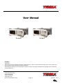
User Manual
72-14110 72-14111
Preface
Dear Users:
Hello! Thank you for choosing this brand new TENMA device. In order to use this instrument safely and correctly, please read
this manual thoroughly, especially the Safety Notes part.
After reading this manual, it is recommended to keep the manual at an easily accessible place, preferably close to the device,
for future reference.

www.element14.com
www.farnell.com
www.newark.com
www.cpc.co.uk
www.mcmelectronics.com
TM
TM
Page <2> V1.028/12/17
Warranty
The TENMA product will be free from defects for a three-year period. If the product is re-sold, the warranty period will be from
the date of the original purchase from an authorized distributor. Probes, other accessories, and fuses are not included in this
warranty.
If the product is proved to be defective within the warranty period, it reserves the rights to either repair the defective product
without charging of parts and labor, or exchange the defected product to a working equivalent product. Replacement parts and
products may be brand new, or perform at the same specications as brand new products. All replacement parts, modules, and
products become the property of TENMA.
The “customer” refers to the individual or entity that is declared in the guarantee. In order to obtain the warranty service,
“customer” must inform the defects within the applicable warranty period to TENMA, and to perform appropriate arrangements
for the warranty service. The customer shall be responsible for packing and shipping the defective products to the designated
maintenance center of TENMA, pay the shipping cost, and provide a copy of the purchase receipt of the original purchaser.
If the product is shipped domestically to the location of the supplier service center, the supplier shall pay the return shipping
fee. If the product is sent to any other location, the customer shall be responsible for all shipping, duties, taxes, and any other
expenses.
This warranty shall not apply to any defects or damages caused by acciendental, machine parts’ wear and tear, improper use,
and improper or lack of maintenance. TENMA under the provisions of this warranty has no obligation to provide the following
services:
a) Any repair damage caused by the installation, repair, or maintenance of the product by non TENMA service representatives.
b) Any repair damage caused by improper use or connection to an incompatible device.
c) Any damage or malfunction caused by the use of a power source which does not conform to the requirements of this manual.
d) Any maintenance on altered or integrated products (if such alteration or integration leads to an increase in time or difculty
of product maintenance).
This warranty written by TENMA for this product, and it is used to substitute any other express or implied warranties. The sup-
plier and its distributors do not offer any implied warranties for merchantability or applicability purposes.
For violation of this guarantee, TENMA is responsible for the repair or replacement of defective products is the only remedy
available to customers. Regardless of whether TENMA and its distributors are informed that any indirect, special, incidental, or
consequential damage may occur, the TENMA and its distributors shall not be responsible for any of the damages.
General Safety Overview
This instrument strictly complies with the safety requirements for electronic measuring instrument GB4793 and IEC 61010-1
safety standard during design and manufacturing. Please understand the following safety preventative measures, to avoid per-
sonal injury, and to prevent damage to the product or any connected products. To avoid possible dangers, be sure to use this
product in accordance with the regulations.
Only trained personnels can perform the maintenance program.
Avoid re and personal injury.
Use the correct power line: Only use the dedicated TENMA power supply appointed to the local region or country for this product.
Correct Plug: Don’t plug when the probe or test wire is connected to the voltage source.
Ground the product: This product is grounded through the power supply ground wire. To avoid electric shock, grounding con-
ductors must be connected to the ground. Please be sure that the product is properly grounded before connecting to the input
or output of the product.
Correct connection of oscilloscope probe: Ensure that the probe ground and ground potential are correctly connected. Do
not connect ground wire to high voltage.
Check all terminal ratings: To avoid re and the large current charge, please check all the ratings and the marks on the
product. Please also refer to the product manual for details on the ratings before connecting to the product.

www.element14.com
www.farnell.com
www.newark.com
www.cpc.co.uk
www.mcmelectronics.com
TM
TM
Page <3> V1.028/12/17
Do not operate the product if you suspect it is faulty, and please contact supplier authorized service personnel for inspection.
Any maintenance, adjustment, or replacement of parts must be performed by supplier authorized maintenance personnels.
Maintain proper ventilation
Please do not operate the product in humid conditions
Please do not operate in inammable and explosive environment
Please keep the product surface clean and dry
Safety Terms and Symbols
The following terms may appear in this manual:
Warning: The conditions and behaviors may endanger life.
Note: The conditions and behaviors may cause damage to the product and other properties.
The following terms may appear on the product:
Danger: Performing this operation may cause immediate damage to the operator.
Warning: This operation may cause potential damage to the operator.
Note: This operation may cause damage to the product and devices connected to the product.
The following symbols may appear on the product:
Do not open the case cover or front panel during operation
Only use fuses with ratings listed in the technical index
Avoid circuit exposure: Do not touch exposed connectors and components after power is connected.

www.element14.com
www.farnell.com
www.newark.com
www.cpc.co.uk
www.mcmelectronics.com
TM
TM
Page <4> V1.028/12/17
Table of Contents
Preface 1
Warranty 2
General Safety Overview 2
Safety Terms and Symbols 3
Chapter 1 Introduction 6
1.1 Safety Terms and Symbols . . . . . . . . . . . . . . . . . . . . . . . . . . . . . . . . . . . . . . .6
1.2 General Safety Overview . . . . . . . . . . . . . . . . . . . . . . . . . . . . . . . . . . . . . . . .6
2.1 Main Features 7
2.2 Panels and Buttons . . . . . . . . . . . . . . . . . . . . . . . . . . . . . . . . . . . . . . . . . . .7
2.2.1 Front Panel . . . . . . . . . . . . . . . . . . . . . . . . . . . . . . . . . . . . . . . . . . . 7
3.1 General Inspection 10
3.1.1 Check for Damages Caused by Transport . . . . . . . . . . . . . . . . . . . . . . . . . . 10
3.1.2 Check Accessories . . . . . . . . . . . . . . . . . . . . . . . . . . . . . . . . . . . . . . 10
3.1.3 Machine Inspection . . . . . . . . . . . . . . . . . . . . . . . . . . . . . . . . . . . . . . 11
3.2 Handle Adjustment . . . . . . . . . . . . . . . . . . . . . . . . . . . . . . . . . . . . . . . . . . . 11
3.3 Basic Waveform Output . . . . . . . . . . . . . . . . . . . . . . . . . . . . . . . . . . . . . . . . 11
3.3.1 Frequency Setting . . . . . . . . . . . . . . . . . . . . . . . . . . . . . . . . . . . . . . 11
3.3.2 Amplitude Setting . . . . . . . . . . . . . . . . . . . . . . . . . . . . . . . . . . . . . . . 11
3.3.4 Square Wave Setting . . . . . . . . . . . . . . . . . . . . . . . . . . . . . . . . . . . . . 12
3.3.5 Pulse Wave Setting . . . . . . . . . . . . . . . . . . . . . . . . . . . . . . . . . . . . . . 12
3.3.6 DC Voltage Setting . . . . . . . . . . . . . . . . . . . . . . . . . . . . . . . . . . . . . . 12
3.3.7 Ramp Wave Setting . . . . . . . . . . . . . . . . . . . . . . . . . . . . . . . . . . . . . 12
3.3.8 Noise Wave Setting . . . . . . . . . . . . . . . . . . . . . . . . . . . . . . . . . . . . . 13
3.4 Frequency Measurement . . . . . . . . . . . . . . . . . . . . . . . . . . . . . . . . . . . . . . . 13
3.5 Build-in Help System . . . . . . . . . . . . . . . . . . . . . . . . . . . . . . . . . . . . . . . . . . 13
Chapter 4 Advanced Applications 4.1 ROLL mode 14
4.1 Modulation Waveform Output . . . . . . . . . . . . . . . . . . . . . . . . . . . . . . . . . . . . . 14
4.1.1 Amplitude Modulation (AM) . . . . . . . . . . . . . . . . . . . . . . . . . . . . . . . . . . 14
4.1.2 Frequency Modulation (FM) . . . . . . . . . . . . . . . . . . . . . . . . . . . . . . . . . 18
4.1.3 Phase Modulation (PM) . . . . . . . . . . . . . . . . . . . . . . . . . . . . . . . . . . . 22
4.1.4 Amplitude Shift Keying (ASK) . . . . . . . . . . . . . . . . . . . . . . . . . . . . . . . . 26
4.1.5 Frequency Shift Keying (FSK) . . . . . . . . . . . . . . . . . . . . . . . . . . . . . . . . 30
4.1.6 Phase Shift Keying (PSK) . . . . . . . . . . . . . . . . . . . . . . . . . . . . . . . . . . 34
4.1.7 Pulse Width Modulation (PWM) . . . . . . . . . . . . . . . . . . . . . . . . . . . . . . . 38

www.element14.com
www.farnell.com
www.newark.com
www.cpc.co.uk
www.mcmelectronics.com
TM
TM
Page <5> V1.028/12/17
4.2 Sweep Waveform Output . . . . . . . . . . . . . . . . . . . . . . . . . . . . . . . . . . . . . . . 42
4.2.1 Sweep Selection . . . . . . . . . . . . . . . . . . . . . . . . . . . . . . . . . . . . . . . 42
4.2.2 Start Frequency and Stop Frequency Setting . . . . . . . . . . . . . . . . . . . . . . . . 42
4.2.3 Sweep Mode . . . . . . . . . . . . . . . . . . . . . . . . . . . . . . . . . . . . . . . . . 43
4.2.4 Sweep Time . . . . . . . . . . . . . . . . . . . . . . . . . . . . . . . . . . . . . . . . . 43
4.2.5 Trigger Source Selection . . . . . . . . . . . . . . . . . . . . . . . . . . . . . . . . . . . 44
4.2.6 Trigger Output . . . . . . . . . . . . . . . . . . . . . . . . . . . . . . . . . . . . . . . . 44
4.2.7 Comprehensive Example . . . . . . . . . . . . . . . . . . . . . . . . . . . . . . . . . . . 44
4.3 Arbitrary Wave Output . . . . . . . . . . . . . . . . . . . . . . . . . . . . . . . . . . . . . . . . . 47
4.3.1 Enable Arbitrary Wave Function . . . . . . . . . . . . . . . . . . . . . . . . . . . . . . . 47
4.3.2 Arbitrary Wave Selection . . . . . . . . . . . . . . . . . . . . . . . . . . . . . . . . . . . 47
Chapter 5 Trouble Shooting 47
5.1 No Display On Screen (Black Screen) . . . . . . . . . . . . . . . . . . . . . . . . . . . . . . . . . 47
5.2 No Waveform Output. . . . . . . . . . . . . . . . . . . . . . . . . . . . . . . . . . . . . . . . . . 48
Chapter 6 Services and Supports 48
6.1 Warranty Overview . . . . . . . . . . . . . . . . . . . . . . . . . . . . . . . . . . . . . . . . . . . 48
Appendix A Factory Reset State 48
Appendix B Technical Specications 50
Appendix C Accessories List 54
Appendix D Maintenance and Cleaning 54

www.element14.com
www.farnell.com
www.newark.com
www.cpc.co.uk
www.mcmelectronics.com
TM
TM
Page <6> V1.028/12/17
Chapter 1 Introduction
1.1 Safety Terms and Symbols
The following terms may appear in this manual:
Warning: The conditions and behaviors may endanger life.
Note: The conditions and behaviors may cause damage to the product and other properties.
The following terms may appear on the product:
Danger: Performing this operation may cause immediate damage to the operator.
Warning: This operation may cause potential damage to the operator.
Note: This operation may cause damage to the product and devices connected to the product.
Symbols on the product.
The following symbols may appear on the product:
Alternating Current
Ground Terminal for Testing
Ground Terminal for Chassis
On/Off Button
High Voltage
Caution! Refer to Manual
Protective Ground Terminal
CE logo is a registered trademark of the European Union.
C-tick logo is a registered trademark of Australia.
Environmental Protection Use Period (EPUP)
1.2 General Safety Overview
This instrument strictly complies with the GB4793 safety requirements for electrical equipment and EN61010-1/2 safety stand-
ard during design and manufacturing. It complies with the safety standards for insulated voltage standard CAT II 300V and
contamination level II.
Please read the following safety preventative measures:
To avoid electric shock and re, please use the dedicated TENMA power supply appointed to the local region or country for

www.element14.com
www.farnell.com
www.newark.com
www.cpc.co.uk
www.mcmelectronics.com
TM
TM
Page <7> V1.028/12/17
this product.
This product is grounded through the power supply ground wire. To avoid electric shock, grounding conductors must be con-
nected to the ground. Please be sure that the product is properly grounded before connecting to the input or output of the
product.
To avoid personal injury and prevent damaging the product, only trained personnel can perform the maintenance program.
To avoid re or electric shock, please notice rated operating range and product marks. Do not use the product outside the
rated range.
Please check the accessories for any mechanical damage before usage.
Only use accessories that came with this product.
Please do not put metal objects into the input and output terminals of this product.
Do not operate the product if you suspect it is faulty, and please contact TENMA authorized service personnel for inspection.
Please do not operate the product when the instrument box opens.
Please do not operate the product in humid conditions.
Please keep the product surface clean and dry.
If the equipment is used in a manner not specied by the manufacturer, the protection provided by the equipment may be
impaired.
This device is economical, high-performance, multi-functional single channel waveform generators. It uses direct digital
synthesis (DDS) technology to produce accurate and stable waveforms, with a resolution as low as 1μHz. It can generate ac-
curate, stable, pure and low distortion output signals, also can provide high-frequency vertical edge square waves.
72-14110 & 72-14111’s convenient interface, superior technical indexes and user-friendly graphical display style can help us-
ers to complete tasks quickly and improve work efciency.
2.1 Main Features
Sine wave output of 20MHz/10MHz/5MHz, full frequency range resolution is 1μHz
Square wave/pulse waveform of 5MHz, and its rising, falling, and duty cycle time are adjustable
Using DDS implementation method, with 125M/s sampling rate and 14bits vertical resolution
6-bit high precision frequency counter that is TTL level compatible
Arbitrary waveform storage of 2048 points, and it can store up to 16 groups of nonvolatile digital arbitrary waveforms
Abundant modulation types: AM, FM, PM, ASK, FSK, PSK, PWM
Powerful PC software
4.3-inch high resolution TFT liquid crystal display
Standard conguration interface: USB Device
Supports internal/external modulation and internal/external/manual trigger
Supports sweep output
Easy-to-use multifunctional knob and number keyboard
2.2 Panels and Buttons
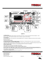
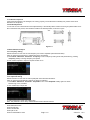
2.2.1 Front Panel
72-14110 & 72-14111 provides users with a simple, intuitive, and easy to operate front panel. The front panel is shown in
gure 2-1:

www.element14.com
www.farnell.com
www.newark.com
www.cpc.co.uk
www.mcmelectronics.com
TM
TM
Page <8> V1.028/12/17
1. Display Screen
4.3-inch TFT LCD displays high-resolution output state, function menu, and other important channel information. It is de-
signed to make human-computer interaction more convenient to improve work efciency.
2. On/Off Button
To turn on/off the device, press this button and its backlight will turn on (orange), the display will show the function interface
after the boot screen.
3. Menu Operation Softkeys
Correspondingly select or check the label contents by identications of softkey labels (at the bottom of function interface).
4. Auxiliary Function and System Settings Button
This button includes 3 function labels: Channel settings, frequency meter, and system. A highlighted label (the midpoint of the
label is gray and font is pure white) has a corresponding sub label at the bottom of the display.
5. Manual Trigger Button
Setting trigger, and carrying out manual trigger when ashing.
6. Modulation/Frequency Meter Input Terminal/Trigger Output Terminal
During AM, FM, PM or PWM signal modulation, when modulation source is external, modulation signal is input through ex-
ternal modulation input. When frequency meter function is on, the signal to be measured is input through this interface; when
manual trigger for channel signal is enabled, manual trigger signal is output through this interface.
7. Synchronous Output Terminal
This button controls whether open synchronous output or not.

www.element14.com
www.farnell.com
www.newark.com
www.cpc.co.uk
www.mcmelectronics.com
TM
TM
Page <9> V1.028/12/17
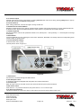
8. CH Control/ Output
Channel output can be turned on/off quickly by pressing Channel button, also can be set by pressing Utility button to pop-up
the label, then pressing the Channel Setting softkey.
9. Direction Buttons
When setting parameters, move left and right to change number bit.
10. Multifunctional Knob and Button
Rotate the multifunctional knob to change numbers (rotate clockwise and numbers increase) or use the multifunctional knob
as direction button. Press the multifunctional knob to select function, set parameters and conrm selection.
11. Number Keyboard
Number keyboard is used to enter parameter number 0 to 9, decimal point “.” and symbol key “+/-”. Decimal point can change
units quickly.
12. Menu Button
3 function labels will pop up by pressing the menu button: Waveform, Modulation, and Sweep. Press the corresponding menu
function softkey to get its function.
13. Functional Menu Softkeys
To select function menu quickly
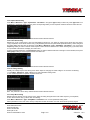
The rear panel is shown in gure 2-2:
Figure 2-2
1. USB Interface
PC software is connected through this USB interface.
2. Heat Dissipation Holes
To ensure this instrument dissipate heat well, please do not block these holes.
3. Insurance Pipe
When AC input current is more than 2A, the fuse will cut off the AC input to protect the device.
4. Main Power Switch
Press down on “I” to power the instrument, and press down on “O” to cut off AC input.
5. AC Power Input Terminal
This device supports AC power from 100V to 240V, 45Hz to 440 Hz, and power fused is 250V, T2 A.

www.element14.com
www.farnell.com
www.newark.com
www.cpc.co.uk
www.mcmelectronics.com
TM
TM
Page <10> V1.028/12/17
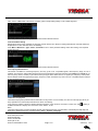
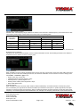
Function interface is shown in gure 2-3:
Detailed Description:
Channel information: 1) “ON/OFF” on the left is channel open information. 2) There is a “Limit” logo indicates output range
limit where white is valid and grey is invalid. The matched impedance of output terminal (1Ω to 1KΩ adjustable, or high
resistance, factory default is 50Ω). 3) The right side is the current valid waveform.
Softkey labels: Softkey labels are used for identifying menu softkey functions and menu operation softkey functions.
1) Labels on the right of screen: Highlighted display indicates that the label is selected. If not, press corresponding softkey
to select.
2) Labels at the bottom of screen: Sub label contents belongs to the next category of Type label. Press corresponding but-
ton to select sub labels.
Waveform Parameter List: Displays parameters of current waveform in a list.
Waveform Display Area: Displays current channel’s waveform.
3.1 General Inspection
It is recommended to follow the steps below to check the instrument before using this device for the rst time.
3.1.1 Check for Damages Caused by Transport
If the packaging carton or the foam plastic cushions are severely damaged, please contact TENMA of this product
immediately.
If the instrument is damaged by transport, please keep the package and contact the transport department and the TENMA
distributor, will arrange for repair or replacement.
3.1.2 Check Accessories
72-14110 & 72-14111 accessories are: Power cord, USB data cable, BNC cable (1 meter), and user CD.
If any of the accessories are missing or damaged, please contact local distributors of this product.

www.element14.com
www.farnell.com
www.newark.com
www.cpc.co.uk
www.mcmelectronics.com
TM
TM
Page <11> V1.028/12/17
3.1.3 Machine Inspection
If the instrument appears to be damaged, not working properly, or has failed the functionality test, please contact local
distributors of this product.
3.2 Handle Adjustment
72-14110 & 72-14111 series handle can be adjusted freely. If the handle position needs to be changed, please hold the han-
dle on both sides and pull out, then rotate the handle to the desired position, as shown in gure
Figure 3-1
3-1:
3.3 Basic Waveform Output
3.3.1 Frequency Setting
Default waveform: A sine wave of 1kHz frequency and 100mV amplitude (with 50Ω termination).
Steps for changing the frequency to 2.5MHz are shown as following:
a) Press Menu→Waveform→Parameter→Frequency in turn to frequency setting mode. Set parameters by pressing
Frequency softkey to change frequency and period.
b) Use number keyboard to input the required number of 2.5.
c) Select corresponding unit MHz.
3.3.2 Amplitude Setting
Default waveform: A sine wave of 100mV peak-peak value with 50Ω termination.
Steps for changing the amplitude to 300mV are shown as following:
1. Press Menu→Waveform→Parameter→Amplitude in turn. Press Amplitude softkey again can switch
between Vpp, Vrms, and dBm.
2. Use number keys to input 300.
3. Select required unit: Press unit softkeymVpp.
Note: This parameter can be set by multifunctional knob and direction buttons.

www.element14.com
www.farnell.com
www.newark.com
www.cpc.co.uk
www.mcmelectronics.com
TM
TM
Page <12> V1.028/12/17
3.3.4 Square Wave Setting
Press Menu→Waveform→Type→Squarewave→Parameter in turn (press Type softkey to select only when Type label is not
highlighted). If parameter needs to be set, press corresponding softkey to enter required numerical value and select the unit.
Note: This parameter can be set by multifunctional knob and direction buttons.
3.3.5 Pulse Wave Setting
Default duty cycle of pulse wave is 50% and rising/falling edge time is 1us. Steps for setting square wave with 2ms period,
1.5Vpp amplitude, 0V DC offset and 25% duty cycle (limited by the minimum pulse width specication 80ns), 200us rising time
and 200us falling time are seen as following: Press Menu→Waveform→Type→PulseWave→Parameter in turn, then press
Frequency softkey to switch to Period. Enter required number value and select the unit. When entering duty cycle value, there
is a quick label at the bottom of display, and select 25%.
If need to set falling edge time, press Parameter softkey or rotate multifunctional knob to the right to enter sub label, then press
Falling Edge softkey to enter required number and select unit.
Note: This parameter can be set by multifunctional knob and direction buttons.
3.3.6 DC Voltage Setting
Actually, DC voltage output is the setting of DC offset. Steps for changing DC offset voltage to 3V are seen as following:
1. Press Menu→Waveform→Type→DC in turn to enter parameter setting mode.
2. Use number keyboard to input the required number of 3.
3. Select required unit V
Note: This parameter can be set by multifunctional knob and direction buttons.
3.3.7 Ramp Wave Setting
Default symmetry degree of ramp wave is 100%. Steps for setting triangular wave with 10kHz frequency, 2V amplitude,
0V DC offset and 50% duty cycle are seen as following:
Press Menu→Waveform→Type→RampWave→Parameter in turn to enter parameter setting mode.
Select parameter to enter edit mode, then input required numbers and select unit. Note: When enter symmetry degree

www.element14.com
www.farnell.com
www.newark.com
www.cpc.co.uk
www.mcmelectronics.com
TM
TM
Page <13> V1.028/12/17
value, there is a 50% label at the bottom of display, press corresponding softkey or use number keyboard.
Note: This parameter can be set by multifunctional knob and direction buttons.
3.3.8 Noise Wave Setting
Default Quasi Gauss noise amplitude is 100mVpp and DC offset is 0mV. Steps for setting Quasi Gauss noise with 300mVpp
amplitude and 1V DC offset are shown as following:
Press Menu→Waveform→Type→Noise→Parameter in turn to enter parameter editing mode. After setting, enter required
number and unit.
Note: This parameter can be set by multifunctional knob and direction buttons.
3.4 Frequency Measurement
This device is suitable for measuring frequency and duty cycle of TTL compatible signals, with frequency range of 1Hz to
100MHz. The frequency meter takes signal through the input interface (Input/CNT terminal). Press Utility then Counter to col-
lect Frequency, Period, and Duty Cycle values from input signal. Note: When there is no signal input, frequency meter param-
eter list always shows last measurement value. Frequency meter will refresh only when new TTL compatible signal is present
at the Input/CNT terminal.
3.5 Build-in Help System
The build-in help system provides relevant information for any button or menu softkey. You also can use help topic list to get
help. Operations for buttons help information are shown as following:
Long press any softkey or button to display relevant information. If the content is more than 1 screen size, use softkey or
multifunctional knob to display the next screen. Press “Return” to exit.
Note!
The built-in help system provides simplied Chinese and English languages. All information, context help and help topic are
displayed in selected language. Language setting: Utility→ System→Language.

www.element14.com
www.farnell.com
www.newark.com
www.cpc.co.uk
www.mcmelectronics.com
TM
TM
Page <14> V1.028/12/17
Chapter 4 Advanced Applications 4.1 ROLL mode
4.1 Modulation Waveform Output
4.1.1 Amplitude Modulation (AM)
Press Menu→Modulation→Type→ Amplitude Modulation in turn to start the AM function. Then the modulated waveform
will output with modulation waveform and carrier wave set.
Carrier Waveform Selection
AM carrier waveform can be: sine wave, square wave, ramp wave or arbitrary wave (except DC), and the default is sine wave.
After selecting AM modulation, press Carrier Wave Parameter softkey to enter carrier waveform selection interface.
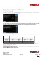
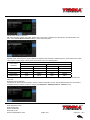
Carrier Wave Frequency Setting
Settable carrier wave frequency range is different for different carrier waveforms. Default frequency of all carrier wave is 1kHz.
The frequency setting range of each carrier wave can be seen in the following table:
Carrier Wave
Frequency
72-14111 72-14110
Minimum Value Maximum Value Minimum Value Maximum Value
Sine Wave 1μHz 10MHz 1μHz 5MHz
Square wave 1μHz 5MHz 1μHz 5MHz
Ramp Wave 1μHz 400kHz 1μHz 400KHz
Arbitrary Wave 1μHz 2MHz 1μHz 1MHz
If need to set carrier frequency, please press Parameter→ Frequency softkey, then enter required numerical value, and
select unit after selecting carrier waveform.
Modulation Source Selection
This device can select internal modulation source or external modulation source. After enabling AM function, the default modu-
lation source is internal. If need to change press
Parameter→Modulation Source→External in turn.

www.element14.com
www.farnell.com
www.newark.com
www.cpc.co.uk
www.mcmelectronics.com
TM
TM
Page <15> V1.028/12/17
1) Internal Source
When modulation source is internal, modulation wave can be: sine wave, square wave, rising ramp wave, falling ramp wave,
arbitrary wave and noise. After enabling AM function, the default of modulation wave is sine wave. If need to change it, press
Carrier Wave →Parameter→Type in turn.
• Square wave: duty cycle is 50%
• Rising Ramp Wave: symmetry degree is 100%
• Falling Ramp Wave: symmetry degree is 0%
• Arbitrary Wave: when arbitrary wave is modulated waveform, DDS function generator limits arbitrary wave length as
1kpts in the way of random selection
• Noise: White Gauss noise
2) External Source
When modulation source is external, parameter list will hide the modulation wave option and modulation frequency option,
and carrier waveform will be modulated by an external waveform. AM modulation depth is controlled by ±5V signal level of ex-
ternal modulation input terminal. For example, if modulation depth value is set to 100%, AM output amplitude is the maximum
when external modulation signal is +5V, AM output amplitude is the minimum when external modulation signal is -5V.
Modulation Shape Frequency Setting
When modulation source is internal, frequency of modulation shape can be modulated. After enabling AM function, range of
modulation wave frequency is 2mHz~50kHz (default is 100Hz). Press Parameter→Modulation Frequency to change. When
modulation source is external, parameter list will hide the modulation shape option and modulation frequency option, and car-
rier waveform will be modulated by an external waveform. The range of modulation signal input from external is 0Hz~ 20Hz.
Modulation Depth Setting
Modulation depth indicates the extent of amplitude variation and is expressed as percentage. Suitable setting range of AM
modulation depth is 0% to 120%, and the default is 100%. When modulation depth is set to 0%, the constant amplitude (a
half of the carrier wave amplitude that has been set) is output. Output amplitude changes as modulation waveform changes
when modulation depth is set to 100%. The instrument output a peak-peak voltage less than ±5V (is connected with 50Ω
terminal) when modulation depth is more than 100%. If need to change, press Parameter→Modulation Depth in amplitude
function interface. When modulation source is external, output amplitude of the instrument is controlled by ±5V signal level of
external modulation input terminal (Input/CNT probe) in rear panel. For example, if modulation depth value in parameter list
has been set to 100%, AM output amplitude is the maximum when external modulation signal is +5V, AM output amplitude is
the minimum when external modulation signal is -5V.
Comprehensive Example
Firstly, make the instrument work in amplitude modulation (AM) mode, then set a sine wave with 200Hz from the internal of
the instrument as a modulation signal and a square wave with frequency of 10kHz, amplitude of 200mVpp and duty cycle of
45% as a carrier wave signal. Finally, set modulation depth to 80%. Specic steps are seen as following:
1) Enable Amplitude Modulation (AM) Function
Press Menu→Modulation→Type→Amplitude Modulation in turn.

www.element14.com
www.farnell.com
www.newark.com
www.cpc.co.uk
www.mcmelectronics.com
TM
TM
Page <16> V1.028/12/17
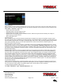
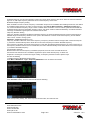
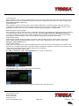
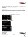
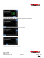
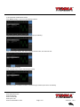
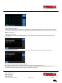
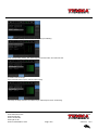
2) Set Modulation Signal Parameter
After enabling the AM function, press Parameter softkey and the interface will appear as following:
Press corresponding softkey, then enter required numerical value, and select the unit.
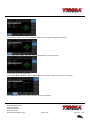
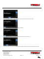
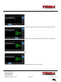
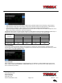
3) Set Carrier Wave Signal Parameter
Press Carrier Wave Parameter→Type→ Square Wave in turn to select square wave as carrier wave signal.
Press Parameter softkey again, and the interface will pop up as following:

www.element14.com
www.farnell.com
www.newark.com
www.cpc.co.uk
www.mcmelectronics.com
TM
TM
Page <17> V1.028/12/17
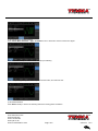
Press corresponding softkey, then enter required numerical value, and select the unit.
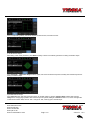
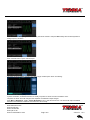
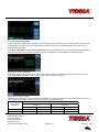
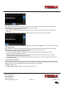
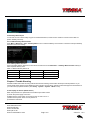
4) Set Modulation Depth
After setting carrier wave parameter, press Return softkey to back to the following interface for setting modulation depth.
Press Parameter →Modulation Degree softkey again, then enter number 80 and press % softkey with number keyboard for
setting modulation depth.
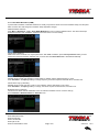
5) Enable Channel Output
Press Channel button start channel output quickly. Or enable output by pressing Channel Setup softkey after pressing
Utility button and popping up labels. After channel output is opened, backlight of Channel button is on, and on the right side
of channel information label, the font “OFF” changes to “ON”, meaning open channel output.

www.element14.com
www.farnell.com
www.newark.com
www.cpc.co.uk
www.mcmelectronics.com
TM
TM
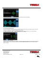
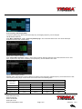
Page <18> V1.028/12/17
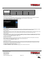
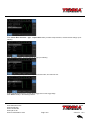
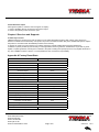
The shape of AM modulation waveform checked through oscilloscope is shown as following:
4.1.2 Frequency Modulation (FM)
In frequency modulation, modulated waveform is usually composed of carrier wave and modulation shape. Carrier wave
frequency will change as the amplitude of modulation shape changes.
Press Menu→Modulation→Type→ Frequency Modulation in turn to start the FM function. The device will output
modulated waveform with modulation waveform and carrier wave set currently.
Carrier Wave Waveform Selection
FM carrier waveform can be: Sine wave, square wave, ramp wave, pulse wave, arbitrary wave (except DC) and noise (the
default is sine wave). After selecting FM modulation, press Carrier Wave Parameter softkey to enter carrier waveform
selection interface.

www.element14.com
www.farnell.com
www.newark.com
www.cpc.co.uk
www.mcmelectronics.com
TM
TM
Page <19> V1.028/12/17
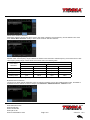
Carrier Wave Frequency Setting
Settable carrier wave frequency range is different of different carrier waveform. Default frequency of all carrier wave is 1kHz.
The frequency setting range of each carrier wave can be seen in the following table:
Carrier Wave
Waveform
Frequency
72-14111 72-14110
Minimum Maximum Minimum Maximum
Sine Wave 1μHz 10MHz 1μHz 5MHz
Square wave 1μHz 5MHz 1μHz 5MHz
Ramp Wave 1μHz 400kHz 1μHz 400KHz
Arbitrary Wave 1μHz 2MHz 1μHz 1MHz
Press Parameter→Frequency softkey in turn to set carrier wave frequency, then enter required numerical value, and select unit.
Modulation Source Selection
This device can select internal modulation source or external modulation source. After enabling FM function, the default of
modulation source is internal. If need to change, press
1) Internal Source
When modulation source is internal, modulation wave can be: sine wave, square wave, rising ramp wave, falling ramp wave,
arbitrary wave and noise. After enabling FM function, the default of modulation wave is sine wave. If need to change, press
Carrier Wave →Parameter→Type in turn.
• Square wave: duty cycle is 50%
• Lead Ramp Wave: symmetry degree is 100%
• Tail Ramp Wave: symmetry degree is 0%
• Arbitrary Wave: Arbitrary wave length limit is 1kpts
• Noise: White Gauss noise
2) External Source
When modulation source is external, carrier waveform will be modulated by an external waveform. FM frequency devia-
tion is controlled by ±5V signal level of external modulation input terminal on front panel. In positive signal level, FM output
frequency is more than carrier wave frequency, while in negative signal level, FM output frequency is less than carrier wave
frequency. Low external signal level has small deviation. For example, if the frequency offset is set to 1kHz and the external

www.element14.com
www.farnell.com
www.newark.com
www.cpc.co.uk
www.mcmelectronics.com
TM
TM
Page <20> V1.028/12/17
modulation signal is +5V, FM output frequency will be the current carrier frequency plus 1kHz. When the external modulation
signal is -5V, FM output frequency will be the current carrier frequency minus 1kHz.
Modulation Shape Frequency Setting
When modulation source is internal, frequency of modulation shape can be modulated. After enabling FM function, the default
of modulation shape frequency is 100Hz. If need to change, press Carrier Wave Parameter→ Modulation Frequency in
turn, and the modulation frequency range is 2mHz to 50kHz. When modulation source is external, parameter list will hide the
modulation shape option and modulation frequency option, and carrier waveform will be modulated by an external waveform.
The range of modulation signal input from external is 0Hz to 20Hz.
Frequency Deviation Setting
Frequency deviation represents the difference between frequency of the FM modulated waveform and the carrier frequency.
Settable range of FM frequency deviation is from 1μHz to the maximum of current carrier wave frequency, and the default
value is 1kHz. If need to change, press
Parameter→Frequency Deviation in turn.
Frequency deviation is less than carrier wave frequency. If frequency deviation value is set higher than carrier wave frequen-
cy, the device will automatically set the offset value to the carrier frequency’s maximum allowable frequency.
Sum of frequency deviation and carrier wave frequency is less than the allowed maximal frequency of current carrier wave. If
the frequency deviation value is set to an invalid value, the device will automatically set the offset value to the carrier frequen-
cy’s maximum allowable frequency.
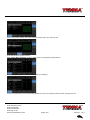
Comprehensive Example:
Make the instrument work in frequency modulation (FM) mode, then set a sine wave with 2kHz from
the internal of the instrument as a modulation signal and a square wave with frequency of 10kHz and
amplitude of 100mVpp as a carrier wave signal. Finally, set frequency deviation to 5kHz. Specic steps
are seen as following:
1) Enable Frequency Modulation (FM) Function
Press Menu→Modulation→Type→Frequency Modulation in turn to start the FM function.
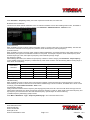
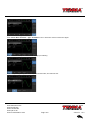
2) Set Modulation Signal Parameter
Press Parameter softkey. Then the interface will show as following:
Press corresponding softkey, then enter required numerical value, and select the unit.
Page is loading ...
Page is loading ...
Page is loading ...
Page is loading ...
Page is loading ...
Page is loading ...
Page is loading ...
Page is loading ...
Page is loading ...
Page is loading ...
Page is loading ...
Page is loading ...
Page is loading ...
Page is loading ...
Page is loading ...
Page is loading ...
Page is loading ...
Page is loading ...
Page is loading ...
Page is loading ...
Page is loading ...
Page is loading ...
Page is loading ...
Page is loading ...
Page is loading ...
Page is loading ...
Page is loading ...
Page is loading ...
Page is loading ...
Page is loading ...
Page is loading ...
Page is loading ...
Page is loading ...
Page is loading ...
-
 1
1
-
 2
2
-
 3
3
-
 4
4
-
 5
5
-
 6
6
-
 7
7
-
 8
8
-
 9
9
-
 10
10
-
 11
11
-
 12
12
-
 13
13
-
 14
14
-
 15
15
-
 16
16
-
 17
17
-
 18
18
-
 19
19
-
 20
20
-
 21
21
-
 22
22
-
 23
23
-
 24
24
-
 25
25
-
 26
26
-
 27
27
-
 28
28
-
 29
29
-
 30
30
-
 31
31
-
 32
32
-
 33
33
-
 34
34
-
 35
35
-
 36
36
-
 37
37
-
 38
38
-
 39
39
-
 40
40
-
 41
41
-
 42
42
-
 43
43
-
 44
44
-
 45
45
-
 46
46
-
 47
47
-
 48
48
-
 49
49
-
 50
50
-
 51
51
-
 52
52
-
 53
53
-
 54
54


Ask a question and I''ll find the answer in the document
Finding information in a document is now easier with AI
Other documents
-
 Scientific SMG1011F Owner's manual
-
 multicomp pro MP750511 Operating instructions
-
 Hantek DDS3005 User manual
-
 Hantek DDS-3X25 User manual
-
SIGLENT SDG1000 Series Function/Arbitrary Waveform Generator User manual
-
-
Rigol DG4000 Series User manual
-
-
-
Rigol DG4102 User manual


