Page is loading ...

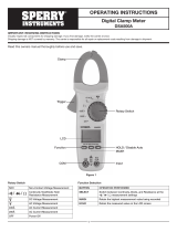
Jaws
Data Hold Button
Function Rotary Switch
Backlight Button
Range Select Button
Display
Input Terminal
Frequency &
Duty Cycle Select Button
High Voltage Indicator
Common / "COM" Terminal
1
OPERATING INSTRUCTIONS
Open Jaw Clamp Meter
DSA200AOC
Read this owner’s manual thoroughly before use and save.
AUTO
DC mVA
nF
%
Hz
kM
Ω
AC
12345
6
7
8
9
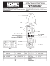
Figure 2
1. Data Hold is enabled 5. Autorange mode is selected
2. Continuity test is selected 6. DC
3. Diode test is selected 7. Negative sign
4. The batteries are low and must be replaced 8. AC
Units of Measure
mV, V Unit of voltage, mV: Millivolt; V: Volt, 1V=1000mV
mA, A Unit of current, µA: Microamp; mA: Milliamp; A: Amper, 1 A = 103mA = 106µA
Ω, kΩ,
MΩ
Unit of resistance, 0: Ohm; kO: Kilohm; MO: Megohm,
1 MΩ = 103kΩ = 106Ω
nF, µF Unit of capacitance, nF: Nanofarad; µF: Microfarad, 1F = 106µF = 109nF = 1012pF
Hz,
kHz,
MHz
Unit of frequency
Hz: Hertz; kHz: Kilohertz; MHz: Megahertz
1 MHz = 103kHz = 106Hz
%Unit of duty cycle, %: Percent
AUTO
DC mVA
nF
%
Hz
kM
Ω
AC
AUTO
DC mVA
nF
%
Hz
kM
Ω
AC
AUTO
DC mVA
nF
%
Hz
kM
Ω
AC
AUTO
DC mVA
nF
%
Hz
kM
Ω
AC
AUTO
DC mVA
nF
%
Hz
kM
Ω
AC
AUTO
DC mVA
nF
%
Hz
kM
Ω
AC
AUTO
DC mVA
nF
%
Hz
kM
Ω
AC
AUTO
DC mVA
nF
%
Hz
kM
Ω
AC
Figure 1
I. DISPLAY FUNCTIONS & SYMBOLS

2
DANGER is reserved for conditions and actions that are likely to cause serious or fatal injury.
WARNING is reserved for conditions and actions that can cause serious or fatal injury.
CAUTION is reserved for conditions and actions that can cause injury or instrument damage.
II. SAFETY WARNINGS
• This instruction manual contains warnings and safety rules which must be observed by
the user to ensure safe operation of the instrument and retain it in safe condition.
• Read through and understand the instructions contained in this manual before using the instrument.
• Keep the manual at hand to enable quick reference whenever necessary.
• The instrument is to be used only in its intended applications.
• Understand and follow all the safety instructions contained in the manual.
• It is essential that all safety instructions are adhered to.
• Failure to follow the safety instructions may cause injury, instrument damage
The symbol indicated on the instrument means that the user must refer to the related parts in the
manual for safe operation of the instrument. It is essential to read the instructions wherever the symbol
appears in the manual.
DANGER
• Never make measurement on a circuit in which voltage over 600V exists.
• Do not exceed the CAT rating of the measuring device
• Do not attempt to make measurement in the presence of flammable gases.
The use of the instrument may cause sparking, which can lead to an explosion.
• Transformer jaw tips are designed to not short the circuit during a test. If equipment under test has exposed
conductive parts extra precaution should be taken to minimize the possibility of shorting.
• Never use the instrument if its surface or your hand is wet.
• Do not exceed the maximum allowable input of any measuring range.
• Never open the battery cover during a measurement.
• The instrument is to be used only in its intended applications or conditions.
Use in other than as intended may cause instrument damage or serious personal injury.
WARNING
• Never attempt to make any measurement if any abnormal conditions are noted, such as broken case,
cracked test leads and exposed metal part.
• Do not turn the function selector switch with plugged in test leads connected to the circuit under test.
• Do not install substitute parts or make any modification to the instrument.
Return the instrument to your distributor for repair or recalibration.
• Do not try to replace the batteries if the surface of the instrument is wet.
• Always switch off the instrument before opening the battery compartment cover for battery replacement.
• Set the Function Switch to an appropriate position before starting measurement.
• Firmly insert the test leads.
• Disconnect the test leads from the instrument for current measurement.
• Do not expose the instrument to the direct sun, high temperature and humidity or dewfall.
• Be sure to power off the instrument after use. When the instrument will not be in use for a long period,
place it in storage after removing the batteries.
• Use only a soft cloth dampened with water or neutral detergent for cleaning the meter.
Do not use abrasives, solvents or harsh chemicals. Allow to dry thoroughly before use.
CAUTION

3
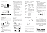
Measurement categories (Over-voltage categories)
To ensure safe operation of measuring instruments, IEC61010 establishes safety standards for various electrical
environments, specified as CAT I through CAT IV, and called measurement categories. Higher-numbered categories
correspond to electrical environments with greater momentary energy, so a measuring instrument designed for CAT III
environments can endure greater momentary energy than one designed for CAT II.
• CAT I: Secondary electrical circuits connected to an AC electrical outlet through a transformer or similar device.
• CAT II: Primary electrical circuits of equipment connected to an AC electrical outlet by a power cord.
• CAT III: Primary electrical circuits of the equipment connected directly to the distribution panel, and feeders
from the distribution panel to outlets.
• CAT IV: The circuit from the service drop to the service entrance, and to the power meter and primary over
current protection device (distribution panel).
Incoming wire Interior wiring
CAT. III
Transformer CAT. II
CAT. I
CAT. IV
Socket
III. GENERAL SPECIFICATION
Display: 3 3/4 digit LCD, with a max. reading of 3999
Overrange indication: "OL" shown on the display
Sampling rate: About 2 - 3 times/sec
Negative Polarity Indication: Negative sign "–"shown on the display automatically
Jaw Opening Capability: 13mm
Max. Measurable Conductor: Ø13mm
Low Battery Indication: " " shown on display
Battery: 1.5V battery, AA or equivalent, two pieces
Operating Environment: Temperature: 0°C to 40°C
Relative Humidity: < 75%RH
Storage Environment: Temperature: -10°C to 50°C
Relative Humidity: < 85%RH
Dimensions: 212x66x33mm
Weight: About 205g (Including batteries; no leads)
AUTO
DC mVA
nF
%
Hz
kM
Ω
AC
Symbols
Caution, risk of danger, refer to the operating manual before use
Caution, risk of electric shock
AC (Alternating Current)
DC (Direct current)
AC/DC Selectable (Alternating Current/Direct Current)
Earth (ground) Terminal
The equipment is protected throughout by
double insulation or reinforced insulation
Application around and removal from hazardous
live conductors is permitted.
Conforms to Standards of European Union
Designates the product as recyclable
electronic waste per WEEE Directive

AUTO
DC mVA
nF
%
Hz
kM
Ω
AC
AUTO
DC mVA
nF
%
Hz
kM
Ω
AC
AUTO
DC mVA
nF
%
Hz
kM
Ω
AC
AUTO
DC mVA
nF
%
Hz
kM
Ω
AC
4
IV. OPERATING INSTRUCTION
A. Data Hold Mode
1. Press the button to hold the present reading on the display, " " will appear on the display as an indicator.
To exit Data Hold mode, just press this button again. " " disappears.
B. Manual Ranging and Autoranging
The meter defaults to autorange mode in measurement functions which have both autorange mode
and manual range mode. When the meter is in autorange mode, the symbol "AUTO" is displayed.
1. Press the RANGE button to enter manual range mode. The symbol "AUTO" disappears.
Each press of the RANGE button increases the range. After the highest range, the meter wraps to the lowest range.
2. To exit the manual range mode, press and hold down the RANGE button for more than about 2 seconds.
The meter returns to the autorange mode and "AUTO" is displayed.
NOTE: Only voltage and resistance functions have both autorange mode and manual range mode.
C. Measuring DC Voltage
1.Connect the black test lead to the "COM" terminal and the red test lead to the "VΩHz " terminal.
2. Set the rotary switch in "V " position. The meter defaults to autorange mode. You can select manual range mode by
pressing the RANGE button. If you use manual range mode and do not know the magnitude of the voltage to be measured
beforehand, select the highest manual range first, and then reduce it range by range until satisfactory resolution is obtained.
3. Connect test leads across the source or circuit to be tested.
4. Observe the reading on the display, The polarity of the red lead connection will be indicated as well.
D. Measuring AC Voltage
1. Connect the black test lead to the "COM" terminal and the red test lead to the "VΩHz " terminal.
2. Set the rotary switch in "V~" position. The meter defaults to autorange mode. You can select manual range mode by
pressing the RANGE button. If you use manual range mode and do not know the magnitude of the voltage to be measured
beforehand, select the highest manual range first, and then reduce it range by range until satisfactory resolution is obtained.
3. Connect the test leads across the source or circuit to be tested.
4. Observe the reading on the display.
E. Measuring AC Current
1. Set the rotary switch in "A~" position.
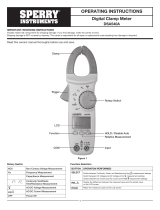
2. Place the conductor (wire) in the jaws. Make sure the wire is centered between
the marks on the meter as shown in figure 3. Only place 1 wire in the jaws at a time.
3. Observe the reading on the display.
F. Measuring Resistance
1. Connect the black test lead to the "COM" terminal and the red test lead to the "VΩHz " terminal.
2. Set the rotary switch in "Ω" position.
3. The meter defaults to autorange mode. You can select a desired manual range with the RANGE button.
4. Connect the test leads across the object to be tested.
5. Observe the reading on the display.
NOTE:
1. For measurements > 1 MΩ, the meter may take a few seconds to stabilize the reading.
This is normal for high resistance measuring.
2. When the input is not connected, i.e. at open circuit, "OL" will be shown on the display as an overrange indication.
3. Before measurement, disconnect all power to the circuit to be tested and discharged all capacitors thoroughly.
4. When you perform a low resistance measurement, short the two test leads’s probes together and read the
resistance value on the display. Subtract this value from the measurement result of the object to be tested.
This can improve the accuracy of low resistance measurement.
G. Measuring Capacitance
1. Connect the black test lead to the "COM" terminal and the red test lead to the "VΩHz " terminal.
(Note: The polarity of the red lead is positive "+".)
2. Set the rotary switch in " " position.
3. Connect the test leads across the capacitor to be tested. Be sure that the polarity of connection is observed when you
measure an electrolytic capacitor.
4. Wait until the reading on the display is stable, then observe the reading.
NOTE:
When the test leads are not connected to a capacitor, the display may show a reading other than zero,
this is normal because of the stray capacitance of the test leads and input circuit of the meter.
You should subtract this reading from the measurement result of the capacitor.
Figure 3

5
H. Measuring Frequency
1. Connect the black test lead to the "COM" terminal and the red test lead to the "VΩHz " terminal.
2. Set the rotary switch in "Hz" position. Then press the "Hz%" button until "Hz" appears on the display.
3. Connect the test leads across the source or circuit to be tested.
4. Observe the reading on the display.
NOTE:
The input voltage should be between 1V rms and 10V rms. If the voltage is more than 10V rms,
the error of reading may be out of the specified accuracy range.
I. Measuring Duty Cycle
1. Connect the black test lead to the "COM" terminal and the red test lead to the "VΩHz " terminal.
2. Set the rotary switch in "Hz" position. Then press the "Hz%" button until "%" appears on the display.
3. Connect the test leads across the circuit to be tested.
4. Observe the reading on the display.
J. Continuity Test
1. Connect the black test lead to the "COM" terminal and the red test lead to the "VΩHz " terminal.
2. Set the rotary switch in " " position. Then press the RANGE button until the symbol " "appears on the display.
3. Connect the test leads across the circuit to be tested.
4. If the resistance is less than about 50Ω, the built-in buzzer will sound and the Light Indicator will light.
NOTE:
Before testing, disconnect all power to the circuit to be tested and discharged all capacitors thoroughly.
K. Diode Test
1. Connect the black test lead to the "COM" terminal and the red test lead to the "VΩHz " terminal.
(Note: The polarity of the red lead is positive "+") ..
2. Set the rotary switch in " " position. Then press the RANGE button until the symbol " " appears on the display.
3. Connect red test lead to the anode of the diode to be tested an
4. Read the approximate forward voltage drop of the diode on the display. If the connections are reversed,
"OL" will be shown on the display.
L. Auto Power Off
1. If you have not operated the meter for about 15 minutes, the meter will sound 5 short beeps and a
long beep and tum off automatically.
2. If you want to turn it on again, set the rotary switch to the "OFF" position first and then set it to a desired position.
M. Backlight Button
1. Press and hold down this " " button for more than 2 secs to turn on the backlight.
To turn off the backlight, press this button.
N. RANGE Button
1. With the rotary switch in voltage or resistance measurement position, this "RANGE" button can be used to
switch between autorange mode and manual range mode as well as to select desired manual range.
2. With the rotary switch in the " " position, you can press this "RANGE" button to switch between diode
and continuity test functions.
O. High Voltage Indicator
1. When the hold button is press this indicator should light briefly.
2. If the indicator fails to light when the hold button is pressed discontinue use of the meter.
3. When the AC voltage being measured is more than 750V or the DC voltage being measured is more than
1000V, this indicator will light as a warning.
4. During a continuity test this indicator will light if the resistance being measured is less than about 50Ω.
/
/
/

6
V. ACCURACY SPECIFICATIONS
Accuracy is specified for a period of one year after calibration and at 18°C to 28°C, with relative humidity <75%.
- Overload Protection: Max. 240A, within 60 seconds.
- Frequency Range: 50Hz - 400Hz
- Response: Average, calibrated in rms of sine wave
AC CURRENT
RANGE RESOLUTION ACCURACY
200A 0.1A ± (3.0% + 3)
- Input Voltage: 1V rms - 10V rms
- Measurement Range: 1 OHz - 1 OOkHz
- Overload Protection: 250V DC/AC rms
FREQUENCY
RANGE RESOLUTION ACCURACY
10Hz 0.01Hz
± (1.5% + 1)
100Hz 0.1Hz
1kHz 1Hz
10kHz 10Hz
100kHz 100Hz
- Input impedance: 10MΩ
- Overload Protection: DC/AC 600V
DC VOLTAGE
RANGE RESOLUTION ACCURACY
400mV 0.1mV ± (0.8% + 3)
4V 1mV
± (0.7% + 1)
40V 10mV
400V 100mV
600V 1V ± (0.8% + 3)
- Input impedance: 10MΩ
- Frequency Range: 40Hz - 400Hz
- Response: Average, calibrated in rms of sine wave
- Overload Protection: DC/AC 600V
AC VOLTAGE
RANGE RESOLUTION ACCURACY
4V 1mV
± (0.8% + 5)
40V 10mV
400V 100mV
400V 1V ±(1%+10)
Input Voltage: 3Vp-p - 10Vp-p
DUTY CYCLE
RANGE RESOLUTION ACCURACY
1%-99% 0.1% 1 Hz - 10kHz: ± (2% + 5)
>10kHZ: not specified
- Overload Protection: 250V DC/AC rms
- For range 1001,1F, measurement time> 30 seconds.
TIP:
If you want to measure a capacitor whose capacitance
is less than 40nF, you can measure another capacitor
whose capacitance is about 1 nF and get a reading,
then connect the two capacitors in parallel and
measure them for the total capacitance reading,
subtract the first reading from the total capacitance
reading, the result is the capacitance value of the
capacitor which you want to measure.
The measuring method mentioned above has
the advantage of better linearity so that the
accuracy of measurement in the 4nF range can
be better than ± (5%+10).
CAPACITANCE
RANGE RESOLUTION ACCURACY
4nF 1pF not specified
40nF 10pF
± (4% + 10)
400nF 100pF
4μF 1nF
40μF 10nF
100μF 100nF ± (8% + 10)
RESISTANCE
RANGE RESOLUTION ACCURACY
400Ω0.1Ω± (1.2% + 3)
4kΩ1Ω
± (1.0% + 2)
40kΩ10Ω
400KΩ100Ω
4MΩ1kΩ± (1.2% + 2)
40MΩ10kΩ± (2.0% + 3)
- Overload Protection: 250V DC/AC rms
DIODE AND CONTINUITY TEST
RANGE DESCRIPTION REMARK
The approximate forward
voltage drop of the diode
will be displayed.
Open Circuit Voltage:
about 1. 48V
If the resistance is less than
about 50Ω, the built-in buzzer
will sound.
If the resistance is between
50Ω and 120Ω, the buzzer
may or may not sound.
If resistance is more than
120Ω, the buzzer won’t sound.
Open Circuit Voltage:
about 0.45V
AUTO
DC mVA
nF
%
Hz
kM
Ω
AC
AUTO
DC mVA
nF
%
Hz
kM
Ω
AC

7
VI. MAINTENANCE
Unless you are replacing the battery, never attempt to repair or service this meter.
Store the meter in a dry place when not in use. Don’t store it in an intense electromagnetic field environment.
A. General Maintenance
Periodically wipe the case with a damp cloth and a little mild detergent. Do not use abrasives or solvents.
Dirt or moisture in the terminals can affect readings. Clean the terminals as follows:
1. Set the rotary switch to the OFF position and remove all the test leads from the meter.
2. Shake out any dirt which may exist in the terminals.
3. Soak a new swab with alcohol.
4. Work the swab around in each terminal.
B. Battery Replacement
To avoid false readings, which could lead to possible electric shock or personal injury,
replace the batteries as soon as the low battery indicator ( ) appears.
Before opening the case or battery cover, disconnect the test leads and tum off the meter.
To replace the batteries, remove the screws on the battery cover and remove the battery cover.
Replace the exhausted batteries with new ones of the same type, make sure that the polarity connections are correct.
Reinstall the battery cover and the screws.
VII. ACCESSORIES
Test Lead: One pair, 10A, with removable caps
Test Leads with caps - CAT IV 600V, CAT III 1000V
Test Leads without caps - CAT II 1000V
WARNING
WARNING
AUTO
DC mVA
nF
%
Hz
kM
Ω
AC

8
Sperry Instruments
800-645-5398
Menomonee Falls, WI 53051
sperryinstruments.com SPR_TL_064_0616
SPERRY INSTRUMENTS LIMITED LIFETIME WARRANTY
Subject to the exclusions and limitations detailed below, Sperry Instruments provides a limited lifetime warranty on products
of its manufacture will be free from defects in materials and workmanship under normal use and service.
Limited
Limited means that Sperry Instruments warrants to the original purchasers of products from Sperry Instruments authorized
distributors at the time of shipment such products shall be free of defects in material and workmanship while the tool is used
under normal working conditions. Standard wear and tear, dulling over time, overloading, misuse, and acts of God are not
covered under warranty. This warranty does not cover batteries, fuses, or test leads.
When a warranty claim arises, the purchaser must contact Sperry Instruments. If the defect comes under the terms of this
limited warranty, Sperry Instruments will arrange, at its sole discretion, one of the following options:
• Product will be replaced
The purchaser is solely responsible for determining the suitability of Sperry products for the purchaser’s use or resale, or
for incorporating them into articles or using them in the purchaser’s applications. The distributor is authorized to extend the
foregoing limited warranty to its original purchasers in connection with the sales of Sperry products, provided that such products
shall not have been altered by the distributor. The distributor shall be fully responsible for any warranties the distributor makes to
its purchasers which are broader or more extensive than Sperry’s limited warranty.
Lifetime Warranty
Warranty Limitation: The forgoing warranties are exclusive and are in lieu of all other express and implied warranties whatsoever,
including but not limited to implied warranties of merchantability and fitness for a particular purpose. The foregoing warranties
do not cover ordinary wear and tear, abuse, misuse, overloading, alterations, products which have not been installed, operated
or maintained in accordance with Sperry’s written instructions. Test leads, fuses, batteries and calibration are not covered under
any implied warranty. “Lifetime” of products that are no longer offered by Sperry will be either repaired or replaced with an item
of Sperry Instruments choice of similar value. Lifetime is defined as 5 years after Sperry discontinued manufacturing the product,
but the warranty period shall be at least ten years from date of purchase. Original proof of purchase is required to establish
original ownership of product.
No warranty will be honored unless an invoice or other proof of purchase date is provided to Sperry Instruments. Hand written
receipts or invoices will not be honored.
©2016 Product Power, LLC All rights reserved.
- See more at: https://www.sperryinstruments.com/en/Resources/Warranty-Information
/