Instruction
Manual
ICAM – Industrial
Charge Amplifier for
Manufacturing
Applications
Type 5073A...
ä
5073A_002-327e-04.23


Foreword
5073A_002-327e-04.23 Page 1
Foreword
Thank you for choosing a Kistler quality product
characterized by technical innovation, precision and long
life.
Information in this document is subject to change without
notice. Kistler reserves the right to change or improve its
products and make changes in the content without
obligation to notify any person or organization of such
changes or improvements.
© 2006 … 2023 Kistler Group. Kistler Group products are
protected by various intellectual property rights. For more
details visit www.kistler.com. The Kistler Group includes
Kistler Holding AG and all its subsidiaries in Europe, Asia,
the Americas and Australia.
Kistler Group
Eulachstrasse 22
8408 Winterthur
Switzerland
Tel. +41 52 224 11 11
www.kistler.com

Contents
Page 2 5073A_002-327e-04.23
Contents
1.Introduction ................................................................................................................................... 4
1.1Enclosed CD ...................................................................................................................... 5
2.Important Notes ............................................................................................................................. 6
2.1For Your Safety .................................................................................................................. 6
2.2Electromagnetic Compatibility (EMC) ............................................................................... 6
2.3Tips on Using this Instruction Manual ................................................................................ 6
2.4Nomenclature .................................................................................................................... 7
2.5Disposal of Electronic Equipment ....................................................................................... 7
2.6Software Upgrades and Updates ....................................................................................... 8
3.Basics ............................................................................................................................................. 9
3.1Unpacking ......................................................................................................................... 9
3.2Storage .............................................................................................................................. 9
3.3Amplifier Variants ............................................................................................................ 10
3.4Accessories Included ........................................................................................................ 10
3.5Optional Accessories ........................................................................................................ 11
4.Fundamentals ............................................................................................................................... 12
4.1The measuring chain ........................................................................................................ 12
4.2Piezoelectric Measurement .............................................................................................. 13
4.3The Mathematical Model of a Piezoelectric Measuring Chain .......................................... 14
4.4The Industrial Charge Amplifier ....................................................................................... 15
5.Description of Amplifier ............................................................................................................... 17
5.1General ............................................................................................................................ 17
5.2Block Diagram ................................................................................................................. 19
5.3Power Supply, Control Inputs and Analog Outputs ......................................................... 20
5.4RS-232C Interface ........................................................................................................... 21
5.5Peak Value Acquisition .................................................................................................... 22
5.6Setting Options – Configuration ...................................................................................... 24
5.6.1Description of the Individual Parameters .......................................................................... 26
6.Commissioning ............................................................................................................................ 28
6.1Installation ....................................................................................................................... 28
6.1.1Connecting Sensors ......................................................................................................... 28
6.1.2Connecting RS-232C and D-Sub 15-pin Male Connector ................................................ 29
6.1.3Power Supply and Digital Inputs ...................................................................................... 29
6.1.4Output Signals ................................................................................................................. 30
7."ManuWare" PC Software ............................................................................................................ 31
7.1Installing "ManuWare" PC Software ............................................................................... 31
7.2Starting the Program ....................................................................................................... 33
7.3Description of the Program Interface ............................................................................... 34
7.4First Simple Measurement – Step by Step ........................................................................ 35
7.4.1Preparations ..................................................................................................................... 35

Contents
5073A_002-327e-04.23 Page 3
7.4.2 Opening the Project – 'Open Project ...' (Ctrl+N) ................................................... 35
7.4.3 Find/Connect Devices – ‘AutoScan’ ........................................................................ 36
7.4.4Defining the Display Interface .......................................................................................... 37
7.4.5Assigning a Channel to a Display Object .......................................................................... 38
7.4.6Starting and Stopping Measurement ................................................................................ 38
7.4.7Optimizing Measurement – Changing the Set Values ....................................................... 39
7.5Backup/Restore Functionality ........................................................................................... 41
8.Maintenance and Diagnostics ...................................................................................................... 43
8.1Inspections during normal operation ................................................................................ 43
8.2Loading New Firmware .................................................................................................... 43
8.3Drift .................................................................................................................................. 47
8.3.1Cause 1 ............................................................................................................................ 47
8.3.2Cause 2 ............................................................................................................................ 48
8.3.3Cause 3 ............................................................................................................................ 48
9.Technical Data .............................................................................................................................. 50
9.1Design Variants ................................................................................................................ 50
9.2Charge Inputs ................................................................................................................... 50
9.3Voltage Outputs (Types 5073Axx1) ................................................................................. 50
9.4Current Output (Types 5073Axx2) ................................................................................... 51
9.5Current output symmetrical (Types 5073Axx5) ................................................................ 52
9.6Measuring Accuracy ......................................................................................................... 52
9.7Dynamic Response of Signal ............................................................................................. 52
9.8Peak Value Acquisition ..................................................................................................... 53
9.9Climatic Operating Conditions ......................................................................................... 53
9.10Power Supply Voltage ...................................................................................................... 54
9.11Control Inputs (Bipolar Optocouplers) .............................................................................. 54
9.12Connectors ....................................................................................................................... 54
9.13LED Indicators .................................................................................................................. 55
9.14Serial Interface .................................................................................................................. 55
9.15Mechanical Data .............................................................................................................. 55
9.16EMC (to conditions of Directive 2014/30/EU) .................................................................. 56
9.17 Dimensions ..................................................................................................................... 57
10.Appendix ...................................................................................................................................... 58
10.1Command Set of RS-232C Interface ................................................................................. 58
10.1.1Command Structure ......................................................................................................... 58
10.1.2Feedback Structure ........................................................................................................... 59
10.1.3Command List .................................................................................................................. 64
10.1.4Examples of Serial Communication ................................................................................... 66
11.Glossary ........................................................................................................................................ 69
11.1Terminology ..................................................................................................................... 69
11.2Measurement Uncertainty ................................................................................................ 73
12.EC Declaration of Conformity ....................................................................................................... 75
Total number of pages: 75

ICAM – Industrial Charge Amplifier for Manufacturing Applications Type 5073A...
Page 4 5073A_002-327e-04.23
1. Introduction
The quality precision Kistler product you have chosen is
characterized by a high level of technical innovation and
built to last.
The Type 5073A... ICAM charge amplifier (Industrial
Charge Amplifier Manufacturing) converts the charge
signal from the piezoelectric sensor into an output voltage
proportional to the mechanical input quantity. Depending
on the version, up to four sensors can be connected, which
can monitor an industrial production process.
Most important performance features at a glance:
Wide, variable measuring range from ±100 ... ±1 000 000
pC
Two independent and variable measuring ranges per
channel; switchable online
Adjustment in sealed case via serial interface
Executable PC software for configuration 1)
LED for visualizing the current operating status
ICAM versions for degrees of protection IP60 and IP65
Integrated peak value memory
Please take the time to thoroughly read this Instruction
Manual. It will help you with the installation, maintenance,
and use of this product.
Kistler offers a wide range of measurement products and
turnkey solutions:
Quartz crystal sensors for measuring force, torque,
strain, pressure, acceleration, shock, vibration and
structural noise
Piezoresistive pressure sensors and transmitters
Measuring amplifiers, indicators and calibrators
Electronic control, monitoring and evaluation systems,
as well as software for specific measurement
applications
Data transmission modules (telemetry)
Kistler also develops and produces complete measuring
solutions for engine, vehicle, manufacturing, plastics and
biomechanics applications.
1) Drivers for Labview Version 7.1 are available but not maint-
ained.

Introduction
5073A_002-327e-04.23 Page 5
Our product and application brochures will provide you
with an overview of our product range. Detailed data
sheets are available for almost all products.
If you need additional help beyond what can be found
either online or in this manual, please contact
Kistler's extensive support organization. Your regional
Kistler sales center or distributor will gladly provide expert
advice – even for application-specific problems.
1.1 Enclosed CD
A CD containing the following is attached inside this
Instruction Manual:
ManuWare setup and test software, incl. online Help
files (HTML, can also be printed out)
Flashloader program and firmware of all devices
supported by ManuWare

ICAM – Industrial Charge Amplifier for Manufacturing Applications Type 5073A...
Page 6 5073A_002-327e-04.23
2. Important notes
Please follow the following instructions, which are intended
to ensure your safety when working with the ICAM Type
5073A… and guarantee a long, trouble-free service life.
2.1 For your safety
The device left the factory in a perfectly safe condition. To
maintain this condition and ensure safe operation, follow
the directions and warnings in this Instruction Manual and
on the device.
Also follow local safety regulations governing the handling
of electrical and electronic equipment.
If it has to be assumed that the amplifier can no longer be
operated safely, switch it off and secure it to ensure it
cannot be switched on again inadvertently.
Safe operation is no longer possible
if the equipment is visibly damaged,
if it is not working properly,
after prolonged storage under adverse conditions,
after being severely impacted in transit.
If any of the above indicate that safe operation is no longer
ensured, the device must be immediately sent to the
responsible Kistler sales center or distributor for repair.
2.2 Electromagnetic compatibility (EMC)
The ICAM Type 5073A… charge amplifier is manufactured
in conformity with CE requirements. It meets the
electromagnetic compatibility safety requirements to EN
61000-6-2 (Immunity) and EN 61000-6-3 (Interference).
2.3 Tips on using this instruction manual
We always recommend that you read the entire Instruction
Manual. However, if you cannot spare the time and are
already familiar with Kistler charge amplifiers, you can limit
yourself to reading the sections containing the information
you currently require.

Important notes
5073A_002-327e-04.23 Page 7
Keep this Instruction Manual in a safe place where it is
readily accessible at all times. Please ask the responsible
Kistler sales center or distributor for a replacement copy if it
is lost. A copy of this Instruction Manual can also be
downloaded from our website www.kistler.com.
Modifications (conversion, retrofitting, etc.) to the amplifier
generally also result in changes to the Instruction Manual. In
this case, please ask the responsible Kistler sales center or
distributor about the options for updating your
documentation.
2.4 Nomenclature
The following table explains the nomenclature and
abbreviations used in this Instruction Manual:
Explanation
M.U. Mechanical Unit,
depending on the type of sensor used, for
example:
pressure in bar
force in N or kN
strain in
pC pico Coulomb = unit of electric
charge
1 pC = 10-12 C or 1 C = 1 As
V Volt = unit of electric voltage
1 V = 1 000 mV
FS Full Scale = full scale value
2.5 Disposal of electronic equipment
Old electronic equipment must not be disposed of in
domestic or residual waste. For disposal at end of life,
please return this product to an authorized electronic
waste disposal service or contact your nearest Kistler
sales office.

ICAM – Industrial Charge Amplifier for Manufacturing Applications Type 5073A...
Page 8 5073A_002-327e-04.23
2.6 Software upgrades and updates
Upgrades or updates for embedded software supplied by
Kistler must be installed.
Kistler accepts no liability for direct damage or
consequential damage caused by products with embedded
software that is not up to date.

Basics
5073A_002-327e-04.23 Page 9
3. Basics
3.1 Unpacking
Check all the device packaging for damage in
transit. Report such damage to the freight forwarder and
the responsible Kistler sales center or distributor.
Please check the included accessories before
commissioning the device (see section 6). Please contact
the responsible Kistler sales center or distributor if there is
anything missing.
3.2 Storage
Take the following safety precautions if prolonged storage
is envisaged.
The temperature must lie in the range –40°C to 80°C.
Cover the sensor connections with a non-shorting dust
cap.
The surroundings should be as dry as possible.
If possible the amplifier should be stored in its original
packaging until used.

ICAM – Industrial Charge Amplifier for Manufacturing Applications Type 5073A...
Page 10 5073A_002-327e-04.23
3.3 Amplifier variants
The following key shows the available variants:
Type 5073A (opt.) Y0
1 channel/acquisition of 1 peak
value 1
2 channels/acquisition of 2 peak
values 2
3 channels/acquisition of 3 peak
values 3
4 channels/acquisition of 2 peak
values 4
4 charging channels summed to 1
channel 5
BNC neg. connector (IP60) 1
TNC neg. connector (IP65) 2
Output signal voltage
-10 … ±10 V 1
Output signal current
4 … 20 mA (available for 1 and
2-channel versions only)
2
Output signal current symmetric
12 ±8 mA (available for 1 and
2-channel versions only)
5
With a fixed, customized time
constant; specify per channel
when ordering, incl.
high (>10 000 pC) or low (<10
000 pC) charge levels
488
For supply voltage
9 … 16 V (available for 1 and 2-
channel versions only)
489
3.4 Accessories included
The ICAM charge amplifier is supplied with:
Item No./
Type
D-Sub 15, female, IP40
with metalized cover and jackscrews
Null modem mini adapter (gender changer)
D-Sub 09, male, D-Sub 09, female
ManuWare CD with
the ManuWare program
the latest firmware for all supported
devices
Flashloader programs for all supported
devices
65016033
1489
65016164

Basics
5073A_002-327e-04.23 Page 11
IP67 cover fo
r
RS-232C, D-Sub 09 female,
connector
Operating Instructions
Calibration certificate
With ICAM Type 5073A5xx
2 dust caps for sensor connection
65008385
3.5 Optional accessories
Item No./
Type
RS-232C cable, l = 5 m, null modem,
D-Sub 09 male, D-Sub 09 female
D-Sub 15, female, IP67, with M20x1.5
lifting screws for cable diameters 6 ... 12
mm
D-Sub 15 female, IP40, with pigtail, l = 5
m
D-Sub 15 female, IP40, with pigtail ,
length to order
(Lmin = 1 m/Lmax = 10 m)
D-Sub 15 female, IP65, with pigtail, l = 5
m
D-Sub 15, female, IP65, with pigtail,
length to order
(Lmin = 1 m/Lmax = 10 m)
Converter, USB 1.1 to RS-232C,
D-Sub 09 male, USB 1.1
Adapter, TNC pos. – BNC neg.
1200A27
65016052
1500A41A5
1500A41Asp
1500A42A5
1500A42Asp
2867
1709

ICAM – Industrial Charge Amplifier for Manufacturing Applications Type 5073A...
Page 12 5073A_002-327e-04.23
4. Fundamentals
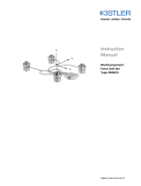
4.1 The measuring chain
The typical measuring chain consists of a piezoelectric
sensor with charge output, a charge amplifier and a system
for cycle command, data acquisition and data evaluation.
In industry, cycle command functionality is usually
implemented with a programmable logic controller (PLC).
Fig. 1: Single-channel measuring chain with charge
amplifier
Key:
1 Sensor
2 Charge amplifier
3 Reset/Measure
4 Measurement signal
5 Signal evaluation
6 Power supply
Piezoelectric
sensor
Connecting cable ICAM
Type 5073A…
PLC
Fig. 2: Example of a measuring chain

Fundamentals
5073A_002-327e-04.23 Page 13
4.2 Piezoelectric measurement
Sensors
Piezoelectric sensors directly convert mechanical quantities,
such as force, pressure and acceleration, into an electric
charge. This charge is proportional to the force acting on
the quartz crystal in the sensor. The sensitivity of the
sensors is given in pC/M.U.
Fig. 3: Force F on the piezoelectric sensor
Notes on piezoelectric measurement
When working with piezoelectric instruments, please note
that these differ from other familiar electrical measuring
instruments. The applicable criteria are different from those
for conventional current or voltage measurement, for
example. When unpacking the sensors and the special
cables ensure that their connectors remain clean and dry, in
order to maintain their high insulation resistance. In
particular, the Teflon insulator of all connector pairs in the
input circuit must be kept absolutely clean and must not be
touched with your fingers. Only use unadulterated
cleaning agents, for example 1003 cleaning spray from
Kistler or white spirits, on a clean, lint-free paper towel.
High insulation sensor cables
Only high insulation, low noise sensor cables, as per Kistler
data sheets 1631C_000-346 and 1601B_000-352, may be
used for connecting the sensors. Normal commercial
coaxial cables generate triboelectricity as a result of
movement, which would falsify the measurement result.
Connecting piezoelectric sensors in parallel
When several sensors are connected in parallel, the
charge amplifier measures the sum of all charges. For
example, the four quartz force links of a measuring
platform can be connected in parallel in order to measure
the total force.
Polarity
Kistler defines polarity in such a way that an increase in
compressive force in a force sensor produces a negative
charge. The charge amplifier inverts the sensor signal and in
this case generates a positive output voltage. The charge
amplifier does not offer an option for additional signal
inversion.

ICAM – Industrial Charge Amplifier for Manufacturing Applications Type 5073A...
Page 14 5073A_002-327e-04.23
Measuring range
We recommend setting the widest measuring range at
the start of measurement or for very intermittent
operation. Normal overdriving by overly-large charge
signals does not damage the charge amplifier. If the
amplifier is overdriven by a factor of more than 10, the
charge can produce an unacceptably high voltage. The
amplitude of the voltage depends on the input charge, the
total input capacitance (sensor and cable) and the range
capacitor.
Measure mode
The major advantage of the charge amplifier principle is
that even quasistatic measurement can be carried out
perfectly. Static measurement is limited by the finite time
constant in the negative feedback circuit, as well as by drift
effects (for example, input current) in the charge amplifier.
4.3 The mathematical model of a piezoelectric measuring chain
The mathematical model of a piezoelectric measuring chain
looks like this:
M
in
process variable
X
in
sensor measurand
Q charge
U
a
amplifier voltage
U
Offset
offset voltage
U
Out
amplifier output voltage
U
display
displayed voltage
X
display
displayed sensor measurand
M
display
displayed process measurand
in
in
M
X
k
Mechanical system factor
(e.g., in force shunt or indirect
force measurement)
in
sensor
X
Q
S
Sensor sensitivity as
p
er
calibration certificate.
Q
U
S
a
ca
Charge am
p
lifier transmission
factor
out
display
U
X
x
Dis
p
lay factor for the sensor
measurand
out
display
U
M
m
Dis
p
lay factor for the
p
rocess
measurand
Fig. 4: Mathematical model of a piezoelectric measuring chain

Fundamentals
5073A_002-327e-04.23 Page 15
4.4 The Industrial charge amplifier
In this context it should be noted that the term "charge
amplifier" does not mean a device that amplifies a charge
Q1 to a value Q2. We use it in the sense of a device for
converting the charge Q into a voltage Ua. A charge
amplifier is therefore a charge-to-voltage converter. It
employs the circuit principle of the integrator. Its key
components are an operational amplifier with very high
internal gain and extremely high input insulation (Rg) as well
as a high-precision, low-loss negative feedback capacitor
(Cg).
Fig. 5: Equivalent circuit diagram of charge amplifier with
charge source
The following approximate formula is adequate for
calculating the voltage signal in most cases:
Ua = -Q/Cg
At the end of each measuring cycle the negative feedback
capacitor is discharged by means of the Reset command
and the output signal is set to zero in order to prevent zero
drift during measurement. The insulation resistance of the
negative feedback capacitor Cg determines the lower cut-
off frequency of the charge amplifier according to the
formula
fu = 1/(2 · Rg · Cg)
The negative feedback capacitor can also be discharged
according to a time constant. This option is available on
request.
Very stringent requirements are imposed on the stability,
low input current and high input insulation of such an
integrator, as the charges to be measured are often just a
few pC. As a result of the high charge sensitivity and high
input resistance, the sensitivity to noise is also relatively
high.
In industrial applications, the sensitivity to interference can
be reduced if the charge amplifier is mounted as close as
possible to the sensor. The signal can then be processed
further away, as the output circuit of the charge amplifier is
low resistance and hence insensitive to interference. Due to

ICAM – Industrial Charge Amplifier for Manufacturing Applications Type 5073A...
Page 16 5073A_002-327e-04.23
the typically metallic shielding of the sensors, cables and
amplifiers, as well as options regarding the grounding
concept, piezoelectric measuring chains from Kistler can
generally achieve high resistance to interference.
In summary, an industrial charge amplifier should have the
following properties:
Compact
Robust, sealed housing
Remote-controlled measurement start and stop
Low-voltage power supply
Several measuring channels
Quick and easy parameter setting
Adaptable to suit special measuring tasks

Description of amplifier
5073A_002-327e-04.23 Page 17
5. Description of amplifier
5.1 General
The charge signal coming from the piezoelectric sensor is
converted by the ICAM Type 5073A… (Industrial Charge
Amplifier Manufacturing) charge amplifier into a
proportional output voltage. The output signals can be
passed on to an industrial control system for monitoring,
control and optimization of a production process. During
the process, the amplifier is controlled via digital inputs and
a serial interface.
Models are available with the same case and bolt
pattern but one, two, three or four channels, each of
which accommodates one sensor.
The Type 5073A5xx ICAM has an integrated summing
amplifier to which up to four sensors can be connected
via the input channels. The amplifier operates like a
single-channel version, where the individual charges of all
four channels are summed into a total charge.
Note therefore, for example, that depending on the total
charge of all the channels, the frequency response can
also change.
The charge input is protected against static discharge and is
ground-isolated. It is allowed to have a potential difference
of up to 4 volts relative to the output or supply voltage.
The ICAM has a rugged pressure diecast aluminum case.
With a wide voltage input range from 18 ... 30 VDC and
degree of protection up to IP60/65, the amplifier is desig-
ned for an industrial environment and mounting in the
immediate vicinity of sensors, for example right alongside a
machine tool.

ICAM – Industrial Charge Amplifier for Manufacturing Applications Type 5073A...
Page 18 5073A_002-327e-04.23
Fig. 6: ICAM Type 5073A...
The ICAM parameters are set with ManuWare PC
software. Virtually any measuring range can be set. For
each sensor connection, two measuring ranges are
available that can also be switched during measurement.
However, for technical reasons this is only permitted
between ±100 to ±10 100 pC and ±10 100 ... ±1 000 000
pC, as otherwise measuring errors will occur. With the
stored peak value, the optimum measuring range can be
determined and hence the highest resolution set. An offset
can be configured for each channel. A low-pass filter can
also be connected. Its cut-off frequency is always valid for
all channels.
Only two peak memory outputs are available on the
version with four channels.
The LED indicates the operating mode of the industrial
charge amplifier. If the ICAM is in Measure mode, the LED
is constantly green. Flashing green indicates Reset mode.
The LED flashes red if the amplifier has been overloaded,
i.e., if the sensor has generated more charge than the
ICAM can accept based on the preselected measuring
range. This can lead to measuring errors. A reset restores
the original state, i.e., the charge amplifier output is set to
zero. The LED is constantly red if the ICAM is faulty.
ICAM mode LED
Measure green, steady
Reset green, flashing
Overload red, flashing
Fault red, steady
Page is loading ...
Page is loading ...
Page is loading ...
Page is loading ...
Page is loading ...
Page is loading ...
Page is loading ...
Page is loading ...
Page is loading ...
Page is loading ...
Page is loading ...
Page is loading ...
Page is loading ...
Page is loading ...
Page is loading ...
Page is loading ...
Page is loading ...
Page is loading ...
Page is loading ...
Page is loading ...
Page is loading ...
Page is loading ...
Page is loading ...
Page is loading ...
Page is loading ...
Page is loading ...
Page is loading ...
Page is loading ...
Page is loading ...
Page is loading ...
Page is loading ...
Page is loading ...
Page is loading ...
Page is loading ...
Page is loading ...
Page is loading ...
Page is loading ...
Page is loading ...
Page is loading ...
Page is loading ...
Page is loading ...
Page is loading ...
Page is loading ...
Page is loading ...
Page is loading ...
Page is loading ...
Page is loading ...
Page is loading ...
Page is loading ...
Page is loading ...
Page is loading ...
Page is loading ...
Page is loading ...
Page is loading ...
Page is loading ...
Page is loading ...
Page is loading ...
/