Page is loading ...

Genebre Building. Av. de Joan Carles I, 46-48
08908 L'Hospitalet de Llobregat. Barcelona (Spain)
genebre@genebre.es - www.genebre.es
GENEBRE S.A.
LAST UPDATE: 23/07/2020 UPDATE NUMBER: 0
1
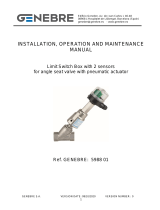
INSTALLATION, OPERATION AND MAINTENANCE
MANUAL
Limit Switch Box with 2 Inductive Detectors
“P + F” NCB2-V3-N0 for Rotary
Pneumatic Actuators
Ref. GENEBRE: 5987 08

Genebre Building. Av. de Joan Carles I, 46-48
08908 L'Hospitalet de Llobregat. Barcelona (Spain)
genebre@genebre.es - www.genebre.es
GENEBRE S.A.
LAST UPDATE: 23/07/2020 UPDATE NUMBER: 0
2
Installation, operation and maintenance instructions
1. Product Description .................................................................................. 3
2. Storage .......................................................................................................... 3
3. Component Parts …………........................................................................ 4
4. Installation instructions ………....……........................................................ 4
4.1 Preparation ................................................................................................... 4
4.2 Installation on the actuator .............................................................................. 5
4.3 Electrical connection …….…...................................................................... 5
4.4 Adjustment of Cams .................................................................................... 6
5. Operational instructions ……………...................................................... 6
6. Maintenance operations ………................................................................... 6
7. Reparation instructions …........................................................................... 7
8. Hygiene and Safety Instructions ................................................................... 7

Genebre Building. Av. de Joan Carles I, 46-48
08908 L'Hospitalet de Llobregat. Barcelona (Spain)
genebre@genebre.es - www.genebre.es
GENEBRE S.A.
LAST UPDATE: 23/07/2020 UPDATE NUMBER: 0
3
1. Product Description.
The limit switch box is used to indicate the position of the valve, open or closed of automated
valves and also hand operated valves.
• These boxes are manufactures in accordance with NAMUR (VDI/VDE 3845).
• Ingress Protection IP 67 according to IEC 60509 standard.
• Easy setting without tool based on spring loaded splinted cam.
• Position indicator of great visibility Open / Closed.
• Dual cable entries M20 x 1,5.
• 8 points and enough strips for electrical connection.
• Bracket with Epoxy Coated painted (Namur 30x80 H=30).
• 2 Inductive Sensors II 1G EEx ia IIC T6.
2. Storage
During storage it is recommended to keep the product in the included protective wrapping to
avoid damages or dirt accumulation. The wrap must not be removed until element is to be
installed. As much as possible, it must be stored in a dry and clean environment.
Transport and storage of these devices must be done in their original wrapping.
VISUAL INSPECTION
Check whether during transport, unloading and placement, devices have suffered no damages.
MECHANICAL INSPECTION
Check whether all mobile parts of the different devices, as well as the screws and other elements, are
accomplishing their purpose.
If you notice any kind of anomaly during reception of the goods, contact immediately
with GENEBRE in order to determine the possible responsibilities on the issue and make the
devices fully operational.

Genebre Building. Av. de Joan Carles I, 46-48
08908 L'Hospitalet de Llobregat. Barcelona (Spain)
genebre@genebre.es - www.genebre.es
GENEBRE S.A.
LAST UPDATE: 23/07/2020 UPDATE NUMBER: 0
4
IMPORTANT NOTE:
Before installing and/or manipullating these pneumatical elements, READ
CAREFULLY these instructions for use and OBSERVE all contained information. If
you fail to understand any of their content, please contact GENEBRE, S.A.
User is responsible for the safe use of these devices, as established in present
instructions for use and in the specific technical documentation of the device.
3. Component Parts
4. Installation instructions
4.1) Preparation
Remove any material remains of the element wrapping.
Prepare a clean working area.
Plan beforehand enough space for future maintenance operations.
It is recommended to perform this task under qualified professional surveillance.
Nº
Name
Spare Part Code
1
Box Cover
-----
2
Cover Bolts
-----
3
Indicator Bolts
----
4
Indicator Cover
C5987
5
Indicator
CI5987
6
Box
-----
7
Detectors
S5987 08
8
Cam
----
9
Shaft
-----
10
Terminal Strip
-----
11
Earth Lug
-----

Genebre Building. Av. de Joan Carles I, 46-48
08908 L'Hospitalet de Llobregat. Barcelona (Spain)
genebre@genebre.es - www.genebre.es
GENEBRE S.A.
LAST UPDATE: 23/07/2020 UPDATE NUMBER: 0
5
4.2) Installation on the actuator
Design according NAMUR VDI / VDE 3845.
The limit swith’s support is designed to be mounted on actuators with a shaft height of H=30,
as well as fixing holes at 80 mm according to Namur standard.
Make sure that both actuator and limit switch are in closed position.
Mount the limit switch by means of the four screws and washers. Apply "cross method" for
tightening.
4.3) Electrical connection
Be extremely cautious before powering the equipment and take into account the power
tension for which it is indicated. Wiring must be done with a cable clamp.
SENSORS FEATURES
Sensor Inductive Model
“P+F” NCB2 – V3 – N0
Ex Identification
II 1G EEx ia IIC T6
Switching element function
NAMUR NC.
Detect Distance
2 mm
Installation
embeddable
Output Polarity
NAMUR
Assured operating Distance
0 ….. 1,62 mm
Nominal Voltage
8 V
Switching frecuency
0 …. 2000 Hz
Hysteresis
Tip. 5% / typ. 5%
Current consumption
Sensor not detected ≥ 3 mA
Sensor detected ≤ 1 mA
Indication of the switching state
Yellow LED
Housing Material
PBT
IP Ratings
IP 67
Working Temperature
-25 / + 100 ºC

Genebre Building. Av. de Joan Carles I, 46-48
08908 L'Hospitalet de Llobregat. Barcelona (Spain)
genebre@genebre.es - www.genebre.es
GENEBRE S.A.
LAST UPDATE: 23/07/2020 UPDATE NUMBER: 0
6
4.4) Adjustment of Cams
The unit is already adjusted in the factory at 0º and 90º, however it could be necessary a
later adjustment in Open and/or Close position:
1. Loosen limit switch box cover screws (part.2) and remove cover (part.1).
2. Rotate actuator to full counterclockwise position. Valve is on fully open position.
3. Lift up bottom cam (part.8) and turn until switch is activated and then release. Engage
cam back onto the splined retainer. Spring will maintain cam engagement.
4. Rotate actuator to full clockwise position. Valve is on fully closed position.
5. Push down top cam (part.8) and turn until switch is activated and then release.
Engage cam back onto the splined retainer. Spring will maintain cam engagement.
6. Place cover (part.1) on limit switch box and tighten the screws (part.2).
5. Operational instructions
Before starting the equipment, you have to read the Technical Specifications and never
exceed the Power limit values.
6. Maintenance operations
Inspect the components of the limit switch box for wear or damage and replace where
necessary.
Top Cam
Bottom Cam

Genebre Building. Av. de Joan Carles I, 46-48
08908 L'Hospitalet de Llobregat. Barcelona (Spain)
genebre@genebre.es - www.genebre.es
GENEBRE S.A.
LAST UPDATE: 23/07/2020 UPDATE NUMBER: 0
7
7. Reparation instructions
Available spare parts see point 3.
Before starting to repair it, disconnect the limit switch box.
¡Use only components/spare parts original or recommended by GENEBRE, S.A
8. Hygiene and Safety Instructions:
When operating any kind of element, you must follow the security instructions and it is
recommended to use personal protection gadgets:
1) Protect your eyes.
2) Wear gloves and appropriate working clothes.
3) Wear safety footwear.
4) Wear a helmet.
5) Have running water at hand.
/


