Page is loading ...

FL-B101D40-RPM (d0073)_UL manual Page 1
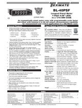
Smart Tri or Mono color digital bargraph
with four fully programmable set points
for RPM measurement.
• ThismeterhasbeendesignedspecificallyforRPMmeasurements.
JustenterthepulesperrevolutionandtheFL-B01D-RPMbargraph
willcalculateanddisplaytheRPMreading.
• Three ranges with resolution of 0.1 RPM, 1 RPM and 10 RPM
(99.99x1000rpmmax).
• Optionalisolated16bitanalogoutput.Userorfactoryscalable
to4to20mA,0to20mAor0to10Vacrossanydesireddigital
spanfrom±onecounttothefullscalerangeof0to9999.
• Standard101segmentRedBarandRed4-digitLEDdisplaywith
arangeof0to9999.OptionalGreenBarandGreenDigitaldis-
play.AlsoOptionalProgrammableTricolor(Red-Green-Orange)
Barisavailable.Verticaloroptionalhorizontalformat.
• FrontpanelLEDannunciatorsprovideindicationofsetpointstatus.
• Two9AmpFormC,andtwo4AmpFormArelaysavailable
• Provisiontoconnectanexternalprogramminglockoutswitch.
• ProvisionforexternalDIMswitchtoreducethebrightest
displaysettingby50%.
• OptionalNEMA-4frontcover.
• Automaticintelligentaveraging,smoothsnoisysignalswhile
providingafastdisplayresponsetoreallevelchanges.
• ULListed
General Features Specifications
Index
FL-B101D40-RPM
• Thebargraphcandisplay,full
scale,anydesiredportionof
thedigitalreading.
•
Bargraphcenterzerofunction.
•
Fourprogrammablesetpoints
withadjustableHysteresis.
• Setpoint1hasdelay-on-make
anddelay-on-breakplus
aspecial“pumponpump
off”modethatcreatesa
Software Features
HysteresisBandbetweenSP1
andSP2.
• Relayactivationcanbeselect-
edtooccurabove(hi)orbelow
(Lo)eachsetpoint.
• Digitaldisplayblanking.
• Decimalpointsetting.
• Four-levelbrightnesscontrol
accessedbythe buttonand
adjustedbythe
button.
BargraphCenterPointDisplayModeSelection... 6
BargraphColorProgrammingMode........ 9
CaseDimensions ....................... 7
ComponentLayout..................... 11
ConnectorPinouts ..................... 10
Connectors........................... 11
ControlsandIndicators.................. 2
CustomFaceplatesandScales ........... 19
DecimalPointandBrightnessSelection..... 5
ProgrammingConventions................ 2
SetpointSetting&RelayConfigurationMode....8-9
SoftwareFeatures...................... 1
SoftwareLogicTree ..................... 3
Specifications.......................... 1
StandardFaceplatesandScales .......... 18
TwoPointAnalogRangeSetting&Calibration .... 7
TwoPointDigitalCalibrationMode......... 4
DigitalSpanSelectionforDisplay.......... 5
DigitalSpanSelectionforAnalogRangeOutput... 6
FunctionalDiagram.................... 10
GeneralFeatures....................... 1
I-SeriesInputSignalConditioningModules...12-15
InputModuleCalibrationProcedures...... 17
InputModuleComponentGlossary........ 16
OrderingInformation................... 20
PinDescriptions ....................... 10
Input Specs:..............DependsonInputsignalconditioner
A/D Converter:..........14bitsingleslope
Accuracy:..................±(0.05%ofreading+2counts)
Temp. Coeff.:.............100ppm/°C(Typical)
Warm up time:...........2minutes
Conversion Rate:......10conversionspersecond(Typical)
Digital Display:..........
4 digit 0.31" LED red (std),green(optn)
Range
0to9999counts.
Bargraph Display:.....
101 segment 4” red vertical (std),
greenortricolor(optn),horizontal(optn)
Polarity:.....................Assumedpositive.Displays–negative
Decimal Selection:....Frontpanelbuttonselectable,X•X•X•X•
Positive Overrange:. . Bargraphandtopsegmentsofdigital
displayflash.
Negative Overrange:Firstsegmentofbargraphandbottom
segmentsofdigitaldisplayflash.
Relay Output:............Two4AmpFormArelaysandTwo
9AmpFormCrelays.
Analog Output:.........Isolated16bituserscalablemAorV
OIC(mAout)...........
4-20mA@0to500Ωmaxloopresistance
OIV(voltsout).......... 0-10VDC@500Ωorhigherresistance
Power Supply:...........AC/DCAutosensingwiderangesupply
PS1 (std)................
85-265 VAC / 95-300 VDC, 50-400Hz 4.2W
PS2.........................
18-48VAC/10-72VDC,50-400Hz4.2W
Operating Temp.:......0to50°C
Storage Temp:...........–20°Cto70°C
Relative Humidity:....95%(noncondensing)
Case Dimensions:....
9/64DIN(Bezel36Wx144Hmm)
Depthbehindbezel(5.83")148mm
Plus(0.7”)18mmforconnectors
Weight:.......................9.5oz.,12ozwhenpacked
101Segment,4Digit0.32”LEDs
ina9/64DINCASE

Page2 FL-B101D40-RPM(d0073)_UL manual
Front Panel Buttons
Program Button
The
P
buttonisusedtomovefromoneprogramsteptothenext.
When pressed at the same time as the button, it initiates the
calibration mode.Whenpressedatthesametimeasthe but-
ton,itinitiatesthesetpoint setting mode.
UP
Button
DOWN
Button
PROGRAM
Button
LED
Annunciators
forSetpoints
1-4
SevenSegment
LEDDisplay
101Segment
Bargraph
Up Button
Whenintheoperationaldisplay,pressingthe buttonallowsyou
toviewthesettingofthesaved Peak and Valley Values.
When setting a displayed parameter during programming, the
buttonisusedtoincreasethevalueofthedisplayedparameter.
Down Button
Whenintheoperationaldisplay,pressingthe buttonallowsyou
tochangethe Brightness Level aswellastoviewthesettingof
thesetpointsSP1, SP2, SP3 & SP4.
When setting a displayed parameter during programming, the
buttonisusedtodecreasethevalueofthedisplayedparameter.
Front Panel LED Display
Annunciator LEDs
TheannunciatorLEDsindicatethealarmstatus.Theyarelabeled
frombottomtotop:SP1,SP2,SP3,SP4.
Digital LED Displays
The digital LED displays are used to display the meter input
signal readings. They also display the programming settings
duringprogramming.
Setpoint Indication
Thepositionofsetpointsonthebargraphdisplayareindicatedby
anONorOFFsegmentdependentonthebargraphdisplaybeing
aboveorbelowthesetpoint.
Setpoints
indicated
byanON
Segment
Setpoints
indicated
byanOFF
Segment--
Controls and Indicators
Thissymbolrepresentsthe
OPERATIONALDISPLAY.
ThisisthePROGRAMbutton.
ThisistheUPbutton.
ThisistheDOWNbutton.
When a button is shown, press and
releaseit to go onto the next step in the
direction indicated by the arrow. When
an alternative dotted line is shown, this
indicates that an alternative logic branch
will be followed when a particular option
ispresent.
Whentwobuttonsareshownsidebyside
andenclosedbyadottedline,theymust
bepressedatthesametimethenreleased
togoontothenextprogrammingstep.
IfanXappearsthroughadigit,itmeansthat
anynumberdisplayedinthatdigitisnotrel-
evanttothefunctionbeingexplained.
P
[Span]
[10000]
P
P
When the
and
buttons are shown
together,thedisplayvaluecanbeincreased
by pressing and releasing the
button
ordecreasedbypressingandreleasingthe
button.
When the
and
buttons are shown
with two displays, either display can be
selectedbypressingandreleasingthe
or
buttons.
When two displays are shown together
withbursts,thisindicatesthatthedisplayis
toggling(flashing)betweenthenameofthe
functionandthevalue.
Text or numbers shown between square
brackets in a procedure indicate the pro-
grammingcodenameofthefunctionorthe
valuedisplayedonthemeterdisplay.
Whentherearemorethantwodisplayselec-
tionstheyareshowninbracketsbelowthe
first display and are also selectable by
pressingandreleasingthe
or
buttons.
A dotted line enclosing an entire logic dia-
gram indicates that programming branch
willappear onlywhena particularoptionis
present.
Toexplainsoftwareprogrammingprocedures,logicdiagramsare
usedtovisuallyassistinfollowingtheprogrammingsteps.The
followingsymbolsareusedthroughoutthelogicdiagramsto
representthebuttonsandindicatorsonthemeter:
Programming Conventions
[X•XXX]
[XX•XX]
[XXX•X]
[XXXX•]
[XXXX]

FL-B101D40-RPM (d0073)_UL manual Page 3
TheFL-B101D40-RPMisanintelligentbargraphmeterwithahier-
archical software structure designed for easy programming and
operation,asshownbelowinthesoftwarelogictree.
Software Logic Tree
Peak
[PEAK]
Reset
PEAK
Reset
VALY
Valley
[VALY]
[orAn]
[rEd]
NOTE: Will only
appear if a tricolor
display is installed
[orAn]
[rEd]
[orAn]
[rEd]
[orAn]
[rEd]
[orAn]
[rEd]
BARGRAPH COLOR
PROGRAMMING MODE
See Page 9
Tricolor Bargraph
The tri-color bargraph is
designed like a traffic light, to
display either red, orange or
green, but only one color at a
time. The color to be displayed
is selected in two ways.
The first step is to select the
color to be displayed when the
bar is “below” whichever set
point is set to the lowest
position.
The second step is to select the
color to be displayed when the
bar is above each specific
setpoint, regardless of the order
or position to which the set
points are set.
However, if two or more
setpoints with differently
specified colors are positioned
at the same set point value, the
color specified for the set point
with the highest identifying
number will be displayed. When
setpoints are set to the same
value, the SP4 color overrides
the SP3 color, the SP3 color
overrides the SP2 color, and the
SP2 color overrides the SP1
color.
Set Setpoint 1
[SP1]
Delay-on-Make
[doM]
Delay-on-Break
[dob]
Relays
Activation
[rLYS]
(h) High the
relay
energizes
when the
setpoint is
exceeded.
(L) Low
the relay
energizes
below the
setpoint.
Setpoint 2
[SP2]
Setpoint 2
[SP2]
Setpoint 1
[SP1]
Setpoint 3
[SP3]
NOTE: [dom] [dob]
Functions are only
available for SP1
abd SP3
0 to 9999
seconds
0 to 9999
seconds
Hysteresis
[hYSt]
Hysteresis
[hYSt]
Bar Color
[coL]
Hysteresis
[hYSt]
Hysteresis
[hYSt]
Setpoint 3
[SP3]
Setpoint 4
[SP4]
Setpoint 4
[SP4]
Operational Display
MAIN MENU
PEAK & VALLEY
VIEW & RESET
BRIGHTNESS AND
SETPOINT VIEW MODE
Bargraph Center Point
Display Selection [cto]
This branch will
only appear if
the analog
output option
is installed
Back to
Operational
Display
Digital Display
ON/OFF
Selection [diSP]
Sub-menu MODE
Calibration Mode
Calibration
Input
Calibration
Output
Calibrate Analog
Output Low
[cLo]
Calibrate Analog
Output High
[chi]
Select the Digital
Reading at which
the Analog Output
Hi [chi] will occur
Select the Digital
Reading at which
the Analog Output
Lo [cLo] will occur
This branch will only appear
if the analog output option
is installed
DIGITAL SPAN SELECTION
FOR ANALOG RANGE OUTPUT
See Page 6
DIGITAL DISPLAY ON/OFF
See Page 6
BARGRAPH CENTER POINT
DISPLAY MODE SELECTION
See Page 6
TWO POINT ANALOG OUTPUT
RANGE SETTING AND CALIBRATION
See Page 7
Bargraph Display
Scale Lo Range
Setting [bLo]
Bargraph Display
Scale hi Range
Setting [bhi]
DIGITAL SPAN SELECTION
FOR BARGRAPH DISPLAY
See Page 5
Goes directly
to Zero setting
if Analog Output
is not installed
PULSES PER
REVOLUTION, RANGE
SELECTION
+
–
4.00
+
–
20.00
1 Dimmest
2 Dim
3 Bright
4 Brightest
SETPOINT SETTING AND
RELAY CONFIGURATION MODE
See Page 8
L or h
L or h
L or h
L or h
Display
Brightness
[br]
Delay-on-Make
[doM]
Delay-on-Break
[dob]
0 to 9999
seconds
0 to 9999
seconds
Sub-menu MODE
Software Version is Displayed on Power-up
Whenpowerisapplied,allsegmentsofthebargraphanddig-
italdisplaylightupfor3seconds.Theversionnumberofthe
installedsoftwareisthendisplayedfor2seconds,afterwhich,
theoperationaldisplayindicatestheinputsignal.
15 Second Program Timeout
ExceptforZEROandSPANsettingsintheTwoPointDigitalCalibrationMode
andtheAnalogOutputRangeSettingandCalibrationMode(cLoandchi),the
meter has a 15 second program timeout. If no buttons are pressed for 15
secondsinanyoftheotherprogrammingsequences,themeterwillexitthe
programmingmodeandreturntotheoperationaldisplay.Anyprogramchang-
esthatweremadepriortopressingthe
P
buttonintheprecedingstepwill
notbesaved.

Page 4 FL-B101D40-RPM(d0073)_UL manual
STEP A Enter the Calibration Mode
1)
Pressthe
P
and buttonsatthesametime.Displaytog-
glesbetween[CAL]and[oFF].
2) Pressthe or button.Displaychangesfrom[oFF]to
[on].
3)
Press the
P
button. Display toggles between [CAL] and
[out].
Note:Ifatthispoint,thedisplayskipsdirectlytoSTEPCandtoggles
between [SPAn] and the previous [SPan] setting, the software is
detectingthattheoptionalanalogoutputhardwareisNOTinstalled.
STEP B
Select Pulese Per Revolution, Range Slection
1) Pressthe or buttontoselectCAL
[iP]forPulesePer
RevolutionSlection.
2) Pressthe
P
button.Display toggles between [PPr] and
thepreviousPulesePerRevolutionsetting.
STEP C Enter the Pulese Per Revolution (PPR)
1) Usingthe and buttons,enterthenumberofpulese
per revolution. Any number between 1 and 9999 may be
enterd.
2) Pressthe
P
button.Displaytogglesbetween[rg]andthe
previousrangesetting.
STEP D Select the Range
1) Usingthe and buttons,seletetherequiredrange.
There are three ranges with resolutions of 0.1 (max. 999.9
RPM),1(max.9999RPM)and10RPM(max.99.99x10000
RPM)
2) Pressthe
P
button.
Pulses Per Revolution and Range Selection
MAIN MENU
Operational Display
Sub-menu
MODE
STEP A Calibration
Mode
STEP B Calibration
Mode
STEP C PPR
STEP D Range
To Digital Span Selection for
Bargraph Display Page 5
cAL out/iP branch will only
appear if the analog output
option is installed, otherwise
cAL on goes directly to ZEro
setting
PULSES PER
REVOLUTION, RANGE
SELECTION
To Digital Span Selection
for Bargraph Display
See Page 6
To Two Point Analog
Output Range Setting
and Calibration
See Page 7
[0.1]
[1]
[10]

FL-B101D40-RPM (d0073)_UL manual Page 5
Example
Example
From Pulses Per
Revolution, Range
Selection Mode
See Page 4
STEP A
STEP B
See Example Above
of Bargraph Display
Scale Range
To Digital Span Selection
for Analog Range Output or
Bargraph Center Point
Display Mode Selection
on Page 6
DIGITAL SPAN SELECTION
FOR BARGRAPH DISPLAY
STEP A Enter the Calibration Sub Menu Mode
1) Pressthe
P
and buttonsatthesametime.Displaytoggles
between[CAL]and[oFF].
2) Press the
P
button. Display toggles between [bhi] and the
previous setting.
STEP B Set the Digital Span of the Bargraph Display
(See example
above)
1) Using the and buttons, adjust the display to the
desired highparameterreading,e.g.6000counts.
2) Press the
P
button. Display toggles between [bLo] and the
previoussetting.
3) Using the and buttons, adjust the display to the
desired lowparameterreading,e.g.4000counts.
4) Pressthe
P
button.Displaychangesfrom[4000]to[dP].
Note: If at this point, the display skips directly to STEP E and toggles
between[Cto]and[oFF],thesoftwareisdetectingthattheoptionalanalog
outputhardwareisNOTinstalled.
Digital Span Selection For Bargraph Display
Bargraphdoesnotlightupfor
InputSignalsupto3999counts
BargraphlightsupforInput
Signalsabove4000counts
No bargraph
display
Digital display Digital display
%
100
0
10
30
50
70
90
20
40
60
80
4
3
2
1
P
SP
Bargraph display
ends at
6000 counts
Bargraph display
starts at
4000 counts
At 5000 counts
the bargraph display
will be at midpoint
%
100
0
10
30
50
70
90
20
40
60
80
4
3
2
1
P
SP
Example of Setting the Digital Span of the Bargraph Display
to be Different than the Digital Display Range
The bargraph can be set to display full scale (0-101 bars) any portion
ofthedigitalreadingfromaminimumof100countstoamaximumof
12,000 counts. This provides higher resolution bargraph indication for
thoseapplicationswherethenormaloperatinginputsignalrangeisless
thanthedesiredfullscaledisplayrangeofthedigitaldisplay.
For Example:
If the full scale range of the meter has been set from -1999 to
9999 (0-12,000 counts), but the normal operating range of the
input signal is between 4000 & 6000. The bargraph high parame-
ter [bhi] can be set to 6000 and the bargraph low parameter [bLo]
can be set to 4000.
This means that although the meter could digitally display a signal
from -1999 to 9999 (0-12,000 counts), the bargraph display only
begins to function at a reading of 4000, and reaches full scale
indication at a reading of 6000. Although the digital display will
continue reading up to 9999 before indicating overrange, the bar-
graph display will indicate its overrange by flashing for readings
above 6000.

Page 6 FL-B101D40-RPM(d0073)_UL manual
5000
Center
Point
Single
Bar Lit
0
2500
5000
Center
Point
0
2500
4000
As signal
increases
0
5000
Center
Point
2500
1000
As signal
decreases
+ 1 V
Center
Point
Single
Bar Lit
- 1 V
0 V
+ 1 V
Center
Point
- 1 V
0 V
0.800
As signal
increases
+ 1 V
- 1 V
0 V
Center
Point
-0.800
As signal
decreases
Example of Using the Center Point Bargraph Display Mode
with a Unipolar Input
If the meter's full scale range is set to 5000 counts, the midpoint would
be2500counts.Ifasignalof2500countsisappliedonlyonesegmentat
the2500countmarkwilllightup.Ifasignalof4000countsisappliedthe
segmentsbetweenthecenter segment(2500counts) andthe4000count
marklightup.
Ifasignalof1000countsisapplied,thesegmentsbetweenthecenterseg-
ment(2500counts)andthe1000countmarkwilllightup.
Example of Using the Center Point Bargraph Display Mode
with Bipolar Signal Inputs
Themetermayalsobecalibratedtodisplaysymmetricalbipolarsignalssuch
as±1Vor±10V.Whenthecenterpointdisplaymodeisselected,itwill
thenfunctionasacenterzerometer.Whenpositivesignalsareapplied,the
barwillgoupfromthecenterpoint,andwhennegativesignalsareapplied,
thebarwillgodownfromthecenterpoint.
STEP C Selecting the [Anhi] Digital Value for Analog High Output
1) Usingthe and buttons,adjustthedisplaytothedesired
digitalvalueatwhichthe[chi]CalibratedAnalogHighoutputwill
occur.Fordigitalreadingsoutsidethedigitalspanselected,the
analogoutputwilllinearlyriseabovethevaluesetforchi,uptothe
maximumanalogoutputcapability.However,theanalogoutputwill
notgolowerthanthecalibratedvaluesetforcLo(seebelow).
2) Pressthe
P
button.Displaytogglesbetween[AnLo]and
previous[AnLo]setting.
STEP D Selecting the [AnLo] Digital Value for Analog Low Output
1) Usingthe and buttons,adjustthedisplaytothedesired
digitalvalueatwhichthe[cLo]CalibratedAnalogLowoutputwill
occur.ForDigitalreadingsoutsidetheDigitalSpanselected,the
analogoutputwillnotgolowerthanthecalibratedvaluesetfor
cLo.
2) Pressthe
P
button.Thedisplaytogglesbetween[cto]and
[oFF].
Note:Anytwodigitalspan pointsfrom–1999to9999canbeselected. Thedigital
valuesfor[Anhi]analoghighand[AnLo]analoglowcanbereversedtoprovidea20to
4mAoutput.Thedigitalspanselectedcanbeassmallastwocounts,whenusingthe
analogoutputtofunctionasaControlorAlarmDriver.Smalldigitalspanswillcause
thehighresolution16bitDtoAtoincrementdigitallyinstaircasesteps.
Digital Span Selection for Analog Range OutputDigital Span Selection for Analog Range Output
Bargraph Center Point Display Mode Selection
STEP E
Bargraph Center Point Mode Selection (See example above)
1) Toselectbargraphcenterpointmode,pressthe or
button.Displaychangesfrom[oFF]to[on].
2) Pressthe
P
button.Displaytogglesbetween[diSP]and
[on]or[oFF].
STEP F Digital Display ON/OFF Selection
1) Tosetthedisplayto[oFF],pressthe or button.
Displaytogglesbetween[diSP]and[oFF].
2) Pressthe
P
button.Thedisplayexitsthecalibrationmode
and returns to the operational display. Only the bargraph
displayisonandthedigitaldisplayisoff.
Ifthedigitaldisplayisselectedtobeoff,pressinganybuttonto
makeprogrammingchangesortoviewsetpointsactivatesthedigitaldisplay.
Whenthe procedureiscomplete,the digital displaywillthen automatically
switchoff.
The Display/Bargraph settings are now complete.
Operational Display
STEP E
STEP F
See Example of Bargraph
Center Point Display Mode
Selection Above
From Digital Span Selection
for Analog Range Output Above
or Direct From Digital Span Selection
for Bargraph Display Page 5
if Analog Output Option is Not Present
BARGRAPH CENTER POINT
DISPLAY MODE SELECTION
STEP C
STEP D
This branch will only
appear if the analog
output option is installed
To Bargraph Center
Point Display Mode
Selection Below
From Digital Span
Selection for Bargraph
Display
See Page 5
DIGITAL SPAN SELECTION
FOR ANALOG RANGE OUTPUT

FL-B101D40-RPM (d0073)_UL manual Page 7
Clear Lockable NEMA 4X
Splash Proof Lens Cover
P/N.(OP-N4/144X36 )
133.5mm
(5.27")
Mosaic
Fitting
9/64 DIN
cutout
spacer
To open rear cover,
use a small flat
blade screw driver.
Press down lightly
to release catch and
leaver outwards.
SIDE VIEW
137.7mm
(5.42")
9/64 DIN
cutout
spacer 142.3mm
(5.62")
Max. panel thickness
43mm
(1.7")
For additional strength,
extra Mounting Slide Clips
can be ordered and doubled up
one behind the other.
P/N. (75-DMC144X36)
4.5mm
(0.18")
Metal Surround Case
P/N.(OP-MTL144X36) is pre-installed
at the factory and cannot be removed
without damage to the case.
Two bezel Trim
Strips are supplied with
each Panel Adaptor
Panel Adaptor to fit existing 6" Edgewise
Pointer Meter Cut-Outs P/N.(OP-PA/144x36)
Adaptor uses wide jaw mounting slide
clips.P/N.(75DMC14436B)
When extra panel
mounting tightness is
required,
order the optional
screw mount
clip.
P/N.(OPMTLCLIP)
FRONT VIEW
144mm
(5.69")
36mm
(1.42") 4mm
(0.16")
typical
9/64 DIN
36x144 mm
100
0
10
30
50
70
90
20
40
60
80
4
3
2
1
P
SP
PANEL CUTOUT
138mm
(5.45")
33mm
(1.3")
Snug
Fitting
Loose
Fitting
8 places
7.5mm(0.3")
3.5mm(0.14")
4 places
4 places
32.2 mm
(1.27")
Mosaic
Fitting
133mm
(5.25")
135.2mm
(5.34")
3mm(0.12")
9/64 DIN
cutout
spacer
Case will mount in standard DIN cutouts
Various
bezel colors
are available.
Black is
standard.
The Metal Surround
case uses Metal
Screw Mount Clips
and has a max.
panel thickness
mounting of
7mm(0.28")
TOP VIEW
5mm
(0.20") 117.5mm
(4.64")
18.3mm (0.72")
Straight-thru
Connector
31mm
(1.22")
34mm
(1.34")
Mosaic Fitting
Right-angled
Connector
6mm
(0.24")
10mm
(0.39")
26.5mm (1.05")
Push-On Connector
for FI series IO board
The adapter snaps on
the 36x144 mm
(1.42"x5.69") case and
enables single unit or
stack mounting in an
existing 6" edgewise
pointer meter cut-out.
100
0
25
50
75
100
0
25
50
75
SP1 SP2 SP3 SP4
Zero Span Zero Span
Panel adaptor plates are
available to retrofit most
existing panel cutouts.
31mm
(1.22")
These dimensions are
increased by 2mm (0.08") when
the metal surround case is installed.
For extra strength in portable applications,
the 8 DIN spacers should be snipped
off and the Mosaic fitting cutout used.
Case Dimensions
Operational Display
Sub-menu
MODE
STEP A Calibration
Mode
STEP B Calibration
Mode
STEP E
Calibrate
Analog
Output
Lo
STEP F
Calibrate
Analog
Output
Hi
Will only appear if the analog
output option is installed
To Digital Span Selection
for Bargraph Display
See Page 5
To Two Point Digital
Calibration Mode
See Page 4
Operational Display
TWO POINT ANALOG OUTPUT
RANGE SETTING AND CALIBRATION
+x
–x
4.00
+x
–x
20.00
DetermineiftheAnalogOutputSelectionHeaderisinthe4to20mA(0-20mA)positionorthe0
to10VDCposition.Ifnecessary,themodulemayhavetoberemovedandtheheaderposition
changed(seeComponentLayoutbelow).
Note: Always disconnect power from the meter before removing the analog output module to
adjustthemAorVoltsoutputselectionheaderandreinstallingit.Whenpowerisreconnected,the
meter’ssoftwarewillautomaticallydetectthepresenceorabsenceoftheanalogoutputmodule.
STEP A Enter the Calibration Mode
1) Pressthe
P
and buttonsatthesametime.Displaytogglesbetween[cAL]and[oFF].
2) Pressthe or button.Displaychangesfrom[oFF]to[on].
3) Pressthe
P
button.Displaytogglesbetween[cAL]and[out]inputcalibration.
Note:IfatthispointthedisplayskipsdirectlytotogglebetweenZeroandthepreviousZero
setting,thesoftwareisdetectingthattheoptionalanalogoutputhardwareisNOTinstalled.
STEP B
EntertheTwoPointAnalog[ouT]OutputRangeSettingandCalibrationMode
1) Pressthe
P
button.Displaytogglesbetween[cLo]andaninternalscalefactor.
STEP E SetorCalibrate[cLo]theLowAnalogValueoftheAnalogOutputRange
1) Connectamultimetertoanalogoutputpins17and18(seeRearPanelPinouts
onpage10).Usingthe and buttons,adjusttheanalogoutputtothedesired
lowvalueasmeasuredonthemultimeter.cLomaybeadjustedtoanyvaluefrom
–0.3mAto18mA(mAoutputselected)orfrom–0.6Vto8V(voltoutputselected).
However,theoutputofcLomustalwaysbelessthanthevalueselectedforchi.If
a reversed analog output is desired, the values selected to establish the Digital
Spancanbereversed(seetopofpage6).FordigitalreadingsoutsidetheDigital
Spanselected,theanalogoutputwillnotgoanylowerthanthecalibratedvalueset
forcLo.However,theanalogoutputwilllinearlyriseabovethevaluesetforchi,up
tothethemaximumanalogoutputcapability(seechibelow).
2) Pressthe
P
button.Displaytogglesbetween[chi]andaninternalscalefactor.
STEP F SetorCalibrate[chi]theHighAnalogValueoftheAnalogOutputRange
1) Usingthe and buttons,adjusttheanalogoutputtothedesiredhighvalue
asmeasuredonthemultimeterdisplay.chimaybeadjustedtoanyvaluefrom18
mAto24mA(mAoutput)orfrom8Vto10.3V(voltoutput).However,thevalue
mustbehigherthanthevalueselectedforcLo.Fordigital readingsoutsidethe
DigitalSpanselected,theanalogoutputwilllinearlyriseabovethevaluesetforchi,
uptothemaximumanalogoutputcapability.
2) Pressthe
P
button.Themeterexitsthecalibrationmodeandreturnstothe
operationaldisplay.
Note:TheanalogoutputrangeestablishedbythevaluesselectedforcLoandchiwilloccur,auto-
maticallyscaled,betweenthetwodigitalvaluesselectedforAnHiandAnLo.However,
theanalog
outputcan linearly rise above the chi valueset for digital readingsoutside the digital span
selected.SeeDigitalSpanSelectiononpage6.
Two Point Analog Output Range Setting and CalibrationTwo Point Analog Output Range Setting and Calibration

Page 8 FL-B101D40-RPM(d0073)_UL manual
Operational Display
SETPOINT SETTING
AND RELAY
CONFIGURATION MODE
STEP A
STEP B
STEP C
STEP D
STEP E
STEP F
STEP G
STEP H
STEP I
STEP J
STEP K
STEP L
STEP M
To Step N of Setpoint
Setting and Relay
Configuration Page 9
0 to 9999
seconds
0 to 9999
seconds
0 to 9999
seconds
0 to 9999
seconds
Thefollowingprogrammingstepsarerequiredtoenterthesetpointvaluesandconfiguretherelayfunctions
inameterwithfourrelaysusingfoursetpoints.Generallyiflessthanfourrelaysareinstalled,thesetpoints
withoutrelaysareoperationalinsoftwarefortri-colorcontrolordisplayonlypurposes.Toremoveunwanted
setpointindications,setthemto9999or-1999dependingontherelayactivationmodeselected.
STEP A Enter the Setpoint Mode
1) Pressthe
P
and buttonsatthesametime.Displaytogglesbetween[SP1]andtheprevious
SP1setting.
STEP B Set Setpoint 1 [SP1]
1) Usingthe and buttons,adjustthedisplaytothedesiredSP1value.
2) Pressthe
P
button.Displaytogglesbetween[doM]andtheprevious[doM]setting.
STEP C Set the SP1 Delay-on-Make [doM] Delay Time Setting
1)
Usingthe and buttons,adjustthedisplaytothedesired[doM]value(0to9999seconds).
Thereadingmustcontinuouslyremaininanalarmconditionuntilthisdelaytimehaselapsedbefore
therelaywillmakecontact(energize).
2) Pressthe
P
button.Displaytogglesbetween[dob]andtheprevious[dob]setting.
STEP D Set the SP1 Delay-on-Break [dob] Delay Time Setting
1)
Usingthe and buttons,adjustthedisplaytothedesired[dob]value(0to9999seconds).
Thereadingmustcontinuouslyremaininanon-alarm condition until this delay time has elapsed
beforetherelaywillbreakcontact(de-energize).
2) Pressthe
P
button.Displaytogglesbetween[hYSt]andtheprevious[hYSt]setting.
STEP E Set the Hysteresis [hYSt] Setting for Setpoint 1
1)
Usingthe and buttons,adjustthedisplaytothedesiredhysteresis[hYSt]value.
2) Pressthe
P
button.Displaytogglesbetween[SP2]andtheprevious[SP2]setting.
STEP F Set Setpoint 2 (SP2)
1) Usingthe and buttons,adjustthedisplaytothedesiredSP2value.
2) Pressthe
P
button.Displaytogglesbetween[hySt]andtheprevious[hySt]setting.
STEP G Set the Hysteresis [hYSt] Setting for Setpoint 2
1) Usingthe and buttons,adjustthedisplaytothedesired
hysteresis[hYSt]value
.
2) Pressthe
P
button.Displaytogglesbetween[SP3]andtheprevious[SP3]setting.
STEP H Set Setpoint 3 (SP3)
1)
Usingthe and buttons,
adjustthedisplaytothedesiredSP3value
.
2) Pressthe
P
button.Displaytogglesbetween[SP3]andtheprevious[SP3]setting.
STEP I Set the SP3 Delay-on-Make [doM] Delay Time Setting
1)
Usingthe and buttons,adjustthedisplaytothedesired[doM]value(0to9999seconds).
Thereadingmustcontinuouslyremaininanalarmconditionuntilthisdelaytimehaselapsedbefore
therelaywillmakecontact(energize).
2) Pressthe
P
button.Displaytogglesbetween[dob]andtheprevious[dob]setting.
STEP J Set the SP3 Delay-on-Break [dob] Delay Time Setting
1)
Usingthe and buttons,adjustthedisplaytothedesired[dob]value(0to9999seconds).
Thereadingmustcontinuouslyremaininanon-alarm condition until this delay time has elapsed
beforetherelaywillbreakcontact(de-energize).
2) Pressthe
P
button.Displaytogglesbetween[hYSt]andtheprevious[hYSt]setting.
STEP K Set the Hysteresis [hYSt] Setting for Setpoint 3
1)
Usingthe and buttons,adjustthedisplaytothedesiredhysteresis[hYSt]value
2) Pressthe
P
button.Displaytogglesbetween[SP4]andtheprevious[SP4]setting.
STEP L Set Setpoint 4 (SP4)
1)
Usingthe and buttons,
adjustthedisplaytothedesiredSP4value
.
2) Pressthe
P
button.Displaytogglesbetween[hySt]andtheprevious[hySt]setting.
STEP M Set the Hysteresis [hYSt] Setting for Setpoint 4
1)
Usingthe and buttons,adjustthedisplaytothedesiredhysteresis[hYSt]value
2) Pressthe
P
button.Displaytogglesbetween[rLYS]andthepreviousrelaysetting.
Please Continue On Next Page.
Setpoint Setting and Relay Configuration Mode

FL-B101D40-RPM (d0073)_UL manual Page 9
STEP N
STEP O
STEP P
STEP Q
STEP R
STEP S
STEP T
STEP U
STEP V
[orAn]
[rEd]
NOTE: Will only
appear if a tricolor
display is installed
[orAn]
[rEd]
[orAn]
[rEd]
[orAn]
[rEd]
[orAn]
[rEd]
BARGRAPH COLOR
PROGRAMMING MODE
Operational Display
Operational Display
From From Step L of
Setpoint Setting and Relay
Configuration Page 8
L or h
L or h
L or h
L or h
Tocomplywiththelatestsafetyrequirements,thetri-colorbargraphisdesignedlikeatrafficlight,to
displayeither red,orange orgreen,but only onecolorat a time. When thebarreachesa selected
colorchangepoint,theentirebarwillchangetothecolordesignatedforthatzone.Thiseliminatesany
ambiguityastothesignalstatus,especiallyjustaftertransitioningtoanewzone.
First (StepQ)istoselectthecolortobedisplayed,whenthebaris“below*”,whicheversetpointisset
tothelowestposition.
Second (StepsR,S,T,andU)istoselectthecolortobedisplayedwhenthebarisaboveeachspecific
setpoint,regardlessoftheorderorpositiontowhichthesetpointsareset.
However,iftwoormoresetpointswithdifferentlyspecifiedcolorsarepositionedatthesamesetpoint
value,thecolorspecifiedforthesetpointwiththehighestidentifyingnumberwillbedisplayed.When
setpointsaresettothesamevalue,theSP4coloroverridestheSP3color,theSP3coloroverridesthe
SP2color,andtheSP2coloroverridestheSP1color.
STEP Q Select Bargraph Color when the bar is BELOW* the Setpoint that is set to the lowest
position
1) Usingthe and buttons,selectthedesiredbargraphcolor[grn],[oran]or[red]
2) Pressthe
P
button.Displaytogglesbetween[CSP1]andthepreviouscolorsetting.
STEP R Select Bargraph Color when the bar is ABOVE* SP1 Setpoint
1) Usingthe and buttons,selectthedesiredbargraphcolor[grn],[oran]or[red]
2) Pressthe
P
button.Displaytogglesbetween[CSP2]andthepreviouscolorsetting.
STEP S Select Bargraph Color when the bar is ABOVE* SP2 Setpoint
1) Usingthe and buttons,selectthedesiredbargraphcolor[grn],[oran]or[red]
2) Pressthe
P
button.Displaytogglesbetween[CSP3]andthepreviouscolorsetting.
STEP T Select Bargraph Color when the bar is ABOVE* SP3 Setpoint
1) Usingthe and buttons,selectthedesiredbargraphcolor[grn],[oran]or[red]
2) Pressthe
P
button.Displaytogglesbetween[CSP4]andthepreviouscolorsetting.
STEP U Select Bargraph Color when the bar is ABOVE* SP4 Setpoint
1) Usingthe and buttons,selectthedesiredbargraphcolor[grn],[oran]or[red]
2) Pressthe
P
button.Themeter exitsthesetpoint modeandreturnstothe operational
display.
The Bargraph Color programming mode is now complete.
STEP N Set Relay Activation mode [rLYS] for SP1
(h)Hightherelayenergizeswhenthesetpointisexceeded.(L)Lowtherelayenergizesbelow
thesetpoint.ThesetpointisindicatedfromlefttorightSP1,SP2,SP3,SP4.
1) Usingthe and buttons,select(L)or(h)forthefirstdigit,whichcorrespondstoSP1.
2) Pressthe
P
button.TheSP2RelayActivationdigitbeginstoflash,anditsdecimalpointislit.
STEP O Set High (h) or Low (L) for SP2
1)
Usingthe and buttons,select(L)or(h)fortheseconddigit,whichcorrespondstoSP2.
2)
Pressthe
P
button.TheSP3RelayActivationdigitbeginstoflash,anditsdecimalpointislit.
STEP p Set High (h) or Low (L) for SP3
1) Usingthe and buttons,select(L)or(h)forthethirddigit,whichcorrespondstoSP3.
2)
Pressthe
P
button.TheSP4RelayActivationdigitbeginstoflash,anditsdecimalpointislit.
STEP Q Set High (h) or Low (L) for SP4
1)
Usingthe and buttons,select(L)or(h)forthefourthdigit,whichcorrespondstoSP4.
2) Pressthe
P
button.
Ifamono-colorredorgreendisplayisinstalledthentheSetpointRelayProgrammingModeisnowcompleteandthe
meterreturnstotheoperationaldisplay.
IfatricolorbargraphdisplayisinstalledthentheBargraphColorProgrammingModewillbeenteredand
displaytogglesbetween[CoL]andtheprevioussetting.Colorselectionmenuwillbedisplayed.
Setpoint Setting and Relay Configuration Mode Continued
Bargraph Color Programming Mode
1234
SP
P
*Note:Forhorizontaldisplayfor-
matsBELOW*shouldbereadas,
“totheleft”andABOVE*should
bereadas,“totheright”.

Page 10 FL-B101D40-RPM(d0073)_UL manual
Standardplug-inscrewterminalblocksprovidedbyTexmate:
WARNING
AC and DC input signals and power
supply voltages can be hazardous.
Do Not connect live wires to ter-
minal blocks, and do not insert,
remove or handle terminal blocks with live
wires connected.
!
Connectors
!
WARNING: AC and DC input signals and power supply
voltages can be hazardous. Do Not connect live wires to
screw terminal plugs, and do not insert, remove or handle
screw terminal plugs with live wires connected.
SP3
NOSP1/3
COM
SP1
NC SP1
NO
SP4
NOSP2/4
COM
SP2
NC SP2
NO
LOCK
COMM
DIM
SP3 SP4
SP1
COM 1&3
NO3
NC1
COM 2&4
NC2
NO4
NO1
NO2
SP2
8910 11 12 13 14 15 17 18 19 20 21 23 24
1 2 3
Analog
Output +
Analog
Output – AC
Neutral AC
Line
– DC + DC
or
Signal Input
+24V EXC
(50mA MAX)
GND
This meter uses plug-in type screw terminal connectors for all
input and output connections. The power supply connections
(pins23and24)haveauniqueplugandsocketoutlinetoprevent
cross connection. The main board uses standard right-angled
connectors.
Replacement 2-, 3-, and 4-pin plug connectors are available
(seeAccessories onpage20).
Pins 1 to 3 – Input Signal
Pin 1 Signal Input
Pin 2 +24V Excitation (50mV Max)
Pin 23 GND
Pins 8 to 15 – Relay Output Pins
Pin 8 SP3 NO.NormallyOpen4AmpFormA.
Pin 9 SP1/3 COM.CommonforSP1andSP3.
Pin 10 SP1 NC.NormallyClosed9AmpFormC.
Pin 11 SP1 NO.NormallyOpen9AmpFormC.
Pin 12 SP4 NO.NormallyOpen4AmpFormA.
Pin 13 SP2/4 COM.CommonforSP2andSP4.
Pin 14 SP2 NC.NormallyClosed9AmpFormC.
Pin 15 SP2 NO.NormallyOpen9AmpFormC.
Pins 17 to 21 – Rear Panel Switches
Pin 17 ANALOG OUTPUT (+).mA(0to20mA/4to20mA)
orV(0to10V)outputisheaderselectable.
Pin 18
ANALOG OUTPUT (–).mA(0to20mA/4to20mA)
orV(0to10V)outputisheaderselectable.
Pin 19 Programming LOCK.ByconnectingtheLOCKpin
totheCOMMONpin,themeter'sprogrammed
parameterscanbeviewedbutnotchanged.
Pin 20 COMMON.ToactivatetheLOCKorDIMfunctions
fromtherearofthemeter,therespectivepinshave
tobeconnectedtotheCOMMONpin.Thispinis
connectedtotheinternalpowersupplyground.
Pin 21 DIM.Byconnectingthedisplaydim(DIM)pinto
theCOMMONpin,thedisplaybrightnesssetting
ishalved.
Pins 23 and 24 – AC/DC Power Input
Auto-sensingAC/DCpowersupply.Forvoltagesbetween
85-265VAC/95-300VDC(PS1)or18-48VAC/10-72V
DC(PS2).
Pin 23 AC Neutral / –DC.Neutralpowersupplyline.
Pin 24 AC line / +DC.Livepowersupplyline.
Connector Pinouts
Pin Descriptions
Note:Thesequenceofsetpointoutputsisnow3-1-4-2,enablingdelay
onmake(dom) anddelay on break(dob)to be usedwith bothForm
“C”relays.

FL-B101D40-RPM (d0073)_UL manual Page 11
Component Layout
IF05
RPM
INPUT MODULE
MAIN BOARD
Low-passFilterHeader
20kHz,2kHz,200Hz SignalTypeHeader
AC,mVordigitallogic
SensorHeader
Mag,Namur,Source,Sink
De-couplingHeader
20mHzhighpasslter
Low Voltage
Hi Voltage
COUPLING
INPUT SIGNAL FILTER
MAG
NAMUR
SOURCE
SINK
LOAD
AC
20KHz
2KHz
200Hz
OFF
DC
MAG/AC
LOGIC
GND
+24V
INPUT
High Accuracy Digital Measurement
NPN
Open Collector
Proximity Switch
Normally Pin 1 is at 24V
When sensor is activated Pin 1 goes to 0V
Using NPN Open Collector Proximity Switch 330B
IF05:
Universal Frequency / RPM
PleasegotoIF05inputmoduledatasheetformoredetail
https://www.texmate.com/media/pdf/2018/09/Texmate_IF05.pdf

FL-B101D40-RPM (d0073)_UL manual Page 13
Installation Guidelines
Installation
1.Installandwiremeterperlocalapplicablecodes/reg-
ulations,theparticularapplication,andgoodinstallation
practices.
2.Installmeter in alocationthat does notexceedthe
maximum operating temperature and that provides
goodaircirculation.
3. Separate input/output leads from power lines to
protect the meter from external noise. Input/output
leads should be routed as far away as possible from
contactors,controlrelays,transformersandothernoisy
components.Shieldingcablesforinput/outputleadsis
recommended with shield connection to earth ground
nearthemeterpreferred.
4.A circuit breaker ordisconnectswitchisrequiredto
disconnect power to the meter. The breaker/switch
shouldbeincloseproximitytothemeterandmarkedas
thedisconnectingdeviceforthemeterormetercircuit.
Thecircuitbreakerorwallswitchmustberatedforthe
appliedvoltage(e.g.,120VACor240VAC)andcurrent
appropriate for the electrical application (e.g., 15A or
20A).
5.SeeCase Dimensions sectionforpanelcutoutinfor-
mation.
6.SeeConnector Pinouts sectionforwiring.
7. Use 28-12 AWG wiring, minimum 90˚C (HH) tem-
perature rating. Strip wire approximately 0.3 in. (7-8
mm).
8.Recommendedtorqueonallterminalplugscrewsis
4.5lb-in(0.51N-m).
!

Page 14 FL-B101D40-RPM(d0073)_UL manual
FL-B101D40-RPM
Add to the basic model number the order code suffix for each standard option required. The last suffix is to
indicate how many different special options and or accessories that you may require to be included with this product.
Ordering Example: FL-B101D40-RPM-VRR-PS1-IF05-OIC-R11-OA2 plus ZR and an OP-N4/144X36
Ordering Information
WARRANTY
Texmatewarrantsthatitsproductsarefreefromdefectsinmaterialandworkmanshipunder
normaluseandserviceforaperiodofoneyearfromdateofshipment.Texmate’sobligations
underthiswarrantyarelimitedtoreplacementorrepair,atitsoption,atitsfactory,ofanyof
theproductswhichshall,withintheapplicableperiodaftershipment,bereturnedtoTexmate’s
facility, transportation charges pre-paid, and which are, after examination, disclosed to the
satisfactionofTexmatetobethusdefective.Thewarrantyshallnotapplytoanyequipment
which shall have been repaired or altered, except by Texmate, or which shall have been
subjectedtomisuse,negligence,oraccident.InnocaseshallTexmate’sliabilityexceedthe
originalpurchaseprice. The aforementionedprovisions do not extendtheoriginal warranty
periodofanyproductwhichhasbeeneitherrepairedorreplacedbyTexmate.
USER’S RESPONSIBILITY
We are pleased to offer suggestions on the use of our various products either by way of
printedmatterorthroughdirectcontactwithoursales/applicationengineeringstaff.However,
sincewehavenocontrolovertheuseofourproductsoncetheyareshipped,NOWARRANTY
WHETHER OF MERCHANTABILITY, FITNESS FOR PURPOSE, OR OTHERWISE is made
beyondtherepair,replacement,orrefundofpurchasepriceatthesolediscretionofTexmate.
Usersshalldeterminethesuitabilityoftheproductfortheintendedapplicationbeforeusing,
and the users assume all risk and liability whatsoever in connection therewith, regardless
ofanyof oursuggestionsorstatementsastoapplicationor construction.Inno eventshall
Texmate’sliability,inlaworotherwise,beinexcessofthepurchasepriceoftheproduct.
Texmatecannot assumeresponsibilityforany circuitrydescribed. Nocircuitpatentor soft-
warelicensesareimplied.Texmatereservestherighttochangecircuitry,operatingsoftware,
specifications,andpriceswithoutnoticeatanytime.
BASIC MODEL NUMBER
FL-B101D40-RPM RPM,
101 Seg. Bargraph, 4 Digit ................
Standard Options for this Model Number
Order Code Suffix Description List
DISPLAY
VRR.....Red LED Bargraph w/4 Digit Red DPM, Vertical.......................N/C
VGG ....Green LED Bargraph w/4 Digit Green DPM, Vertical ......................
VGR ....Green LED Bargraph w/4 Digit Red DPM, Vertical ....................... $15
VRG ....Red LED Bargraph w/4 Digit Green DPM, Vertical ....................... $10
VTG.....Tri-Color Bargraph w/4 Digit Green DPM, Vertical ........................ $55
VTR .....Tri-Color Bargraph w/4 Digit Red DPM, Vertical .........................$45
HRR ....Red LED Bargraph w/4 Digit Red DPM, Horizontal ....................... $5
HGG ....Green LED Bargraph w/4 Digit Green DPM, Horizontal.................... $30
HGR ....Green LED Bargraph w/4 Digit Red DPM, Horizontal ..................... $20
HRG ....Red LED Bargraph w/4 Digit Green DPM, Horizontal ..................... $15
HTG ....Tri-Color Bargraph w/4 Digit Green DPM, Horizontal...................... $60
HTR.....Tri-Color Bargraph w/4 Digit Red DPM, Horizontal ....................... $50
DSGG ...Dual Scale Green LED Vertical Bargraph w/4 Digit Green DPM.............. $30
DSGR ...Dual Scale Green LED Vertical Bargraph w/4 Digit Red DPM ............... $20
DSRG ...Dual Scale Red LED Vertical Bargraph w/4 Digit Green DPM ............... $15
DSRR ...Dual Scale Red LED Vertical Bargraph w/4 Digit Red DPM................. $5
DSTG ...Dual Scale Tri-Color Vertical Bargraph w/4 Digit Green DPM................ $60
DSTR ...Dual Scale Tri-Color Vertical Bargraph w/4 Digit Red DPM .................$50
POWER SUPPLY
PS1 .....85-265VAC/95-300VDC ...........................................N/C
PS2 .....15-48VAC/10-72VDC . . . . . . . . . . . . . . . . . . . . . . . . . . . . . . . . . . . . . . . . . . . . . . $35
INPUT MODULES
(Partial List. See www.texmate.com)
Unless otherwise specified Texmate will ship all modules precalibrated with factory pre-
selected ranges and/or scalings as shown in
BOLD
type.
IF05....Universal Frequency / RPM ............................... $40
ANALOG OUTPUT
OIC .....Isolated 16 Bit Current Output, 4-20mA ............................... $35
OIV .....Isolated 16 Bit Voltage Output, 0-10VDC ..............................$35
RELAY OUTPUT
R1 ......Single 4A Form A Relay ........................................... $37
R2 ......Dual 4A Form A Relays ............................................ $68
R11 .....Single 9A Form C Relay ........................................... $35
R12 .....Dual 9A Form C Relays ........................................... $70
R13 .....Dual 9A Form C & One 4A Form A Relays ............................. $100
R14 .....Dual 9A Form C & Dual 4A Form A Relays ............................. $130
R15 .....Single 9A Form C & Dual 4A Form A Relays ............................ $95
R16 .....Single 9A Form C & Single 4A Form A Relays........................... $65
Special Options and Accessories
Part Number Description List
SPECIAL OPTIONS
(Specify Inputs or Outputs & Req. Reading
)
ZR ............... Calibrated Range Change to another Standard Range ...........$20
ZS ............... Custom display scaling within standard ranges .................$24
ZS-AO............ Custom scaling of analog output ............................$60
ACCESSORIES
(Specify Serial # for Custom Artwork Installation)
75-DMC14436B ..... Side Slide Brackets-Wide opening (2 pc).................... $10
75-DMC144X36 ..... Side Slide Brackets-stand. (2 pc) - extra set ................. $10
93-PLUG2P-DP...... Extra Screw Terminal Conn., 2 Pin Power Plug ...............$3
93-PLUG2P-DR ..... Extra Screw Terminal Conn., 2 Pin Plug..................... $3
93-PLUG3P-DR ..... Extra Screw Terminal Conn., 3 Pin Plug..................... $5
93-PLUG4P-DR ..... Extra Screw Terminal Conn., 4 Pin Plug..................... $6
93-PLUG5P-DR ..... Extra Screw Terminal Conn., 5 Pin Plug..................... $7
OP-MTL144x36...... Metal Surround Case, includes screw mounting clips ..........$35
OP-MTLCLIP........
Screw Mounting Clips (2 pc) - to screw tighten slide brackets ........$10
OP-N4/144X36 . . . . . .
144x36mm clear lockable front cover-NEMA 4X, splash proof..........$35
OP-PA/144X36 ...... Panel Adapter for 144x36mm from 6 inch cutout .............$15
For Custom Face Plates and Scales see page 14.
Prices subject to change without notice.
1934KelloggAve.,Carlsbad,CA92008
Tel:1-760-598-9899•USA1-800-839-6283•1-800-TEXMATE
Fax:1-760-598-9828•Email:[email protected]•Web:www.texmate.com
FL-B01Q-RPM Technical Manual Copyright © 2019 Texmate Inc. All rights
reserved. Published by: Texmate Inc. USA. Information in this Technical Manual
is subject to change without notice due to correction or enhancement. The
information described in this manual is proprietary to Texmate, Inc. and may
not be copied, reproduced or transmitted, in whole or in part, in connection with
the design, manufacture, or sale of apparatus, device or private label product
without the express written consent of Texmate, Inc.
BASIC MODEL #
DISPLAY
POWER SUPPLY INPUT MODULES ANALOG OUTPUT RELAY OUTPUT
OPTIONS / ACCESSORIES
OA____
/