Page is loading ...

VACUFLUSH® 4848 TOILET INSTALLATION GUIDE
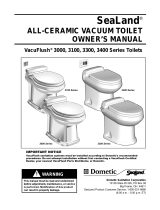
THROUGH-THE-WALL DIAGRAM
FLOOR
toilet
centerline
1 in.
(25mm)
2 in.
(51 mm)
electric cable
location
1.75-in. dia.
(44mm)
discharge hose
location
2-in. dia.
(51mm)
water line
location
1-in. dia.
(25mm)
Electrical Amp draw (average) 2 amps at 12 V DC; 1 amp at 24 V DC
Fuse 2-amp internal fuse (resettable) *
Water
Supply
Fitting 0.5 in. NPT
Flow rate 2.0 gpm/7.6 lpm minimum required at toilet
Discharge
Size 1.5 in./38 mm ID PVC pipe or sanitation hose
Horizontal run 50 ft./15 m maximum to vacuum source
Vertical run 6 ft./1.8 m maximum to vacuum source
Required
components
Electric ush switch Dometic VFS or VFP switch (purchased separately)
Vacuum source VacuFlush vacuum generator or
VacuFlush holding tank system (purchased separately)
* Circuit board fuse resets by turning toilet’s electrical power off, then back on.
Specications subject to change without notice.
Toilet installation specifications
1. Carefully unpack toilet and place it in the approximate position intended. Assure that adequate
clearance is available for opening the seat and lid. Check the front and sides of the toilet to
insure that it will set at against the oor.
2. Insert 0.75-in. (19 mm) spacer between toilet and wall, and reposition toilet against spacer
(g. 1 ), making sure back of toilet is parallel to back wall.
3. Mark oor at the bottom front of toilet (g. 2 ). Remove toilet and spacer, then place oor
mounting template where toilet was originally positioned, aligning front edge of template with
mark on oor representing front edge of toilet.
Note
Choose an inlet conguration for the electrical
wiring and water lines - through the rear wall or
through the oor. Refer to the Through-the-Wall
Diagram (shown at right) to plan access holes if
that is the intended application.
4. Mark all hole centers through template (g. 3 ). Also
mark the locations of the corners of the toilet mounting
brackets.
5. Remove template from oor. Drill all access and fastener holes as indicated on template
(g. 4 ). If electrical wires and water supply are being routed through the wall, be sure to drill
those holes through the wall.
6. Determine the best location for the ush switch panel. It is recommended that the ush switch
be near the toilet but not hidden by the toilet lid in the “up” position. Avoid a location susceptible
to direct water spray. Cable provided with ush switch must reach from switch location to con-
nection in toilet base. Follow instructions provided with ush switch to create access hole in wall.
7. Using PVC primer and solvent cement, solvent weld the desired outlet ttings to the discharge
adapter (g. 5 ). Allow to cure before handling.
8. Mount discharge adapter to the oor (g. 6 ) with screws and at washers provided. Complete
the plumbing to vacuum tank or vacuum generator. Use 1.5-inch OdorSafe Plus exible sanita-
tion hose or 1½-inch PVC schedule 40 pipe.
9. Route 0.5-inch (13 mm) diameter water line from the fresh water source through the 1-inch
(25 mm) hole in the wall or oor and attach a 0.5-inch NPT tting (g. 7 ).
Note
An accessible shut-off valve should be placed in the water line to the toilet for maintenance
or repair.
10. WITH ELECTRICAL POWER OFF, route electrical cables/wiring from vacuum generator and
power source through wiring access hole (g. 7 ). (Refer to wiring diagram on separate toilet
model’s parts list. If wiring connector shown here is not being used, refer to wiring diagram to
make proper connections).
11. Install ush switch according to its instructions and route electrical cable through the wiring
access hole at the toilet (g. 7 ). Leave enough cable to connect to toilet. The cable supplied
with the VacuFlush switch should have ethernet cable connectors (not shown here).
12. Secure the toilet mounting brackets to the oor using the #14 x 2.5-inch (65 mm) hex washer
head screws provided (g. 8 ). Be sure to mount the brackets as shown on the template.
Note
Do not completely tighten hex-head screws to oor – allow brackets to slightly
slide. Brackets will tighten when fastening toilet to brackets.
13. Set the toilet in front of the discharge adapter. Connect the exible water hose to the 1/2-inch
NPT tting on the inlet water line. Connect the cable/wiring from vacuum generator and power
source to the toilet’s vacuum generator-power source cables/wiring (g. 9 ). Connect the
cable from the ush switch to the circuit board located in the toilet’s base (g. 10 ).
Caution!
DO NOT ATTEMPT TO SLIDE TOILET OVER THE FLANGE ADAPTER. THE TOILET MUST
BE SET DOWN INTO THE DISCHARGE ADAPTER TO PREVENT POSSIBLE DAMAGE.
14. Lubricate the O-ring around the bottom of the toilet base with silicone grease. Pick up the toilet
and insert plastic toilet base assembly into discharge adapter (g. 11 ). Make sure mounting
brackets on oor do not interfere with bottom of ceramic toilet, and that toilet sits at on oor
(g. 12 ). If the mounting brackets interfere, adjust bracket position accordingly.
15. Making sure that toilet mounting holes align with brackets, insert the two plastic ange bushings
into the toilet mounting holes and secure the toilet to the mounting brackets with the two at
head wood screws provided (g. 13 ). Be sure to drive fasteners into mounting brackets at a
downward angle.
16. Press the decorative screw covers over the ange bushings (g. 14 ).
17. Turn on electrical and water supplies, and test toilet for proper operation..
2
1
3/4 in.
(19 mm)
3
5
7
9
11
6
8
4
14
12
13
10
© Dometic Corporation
All rights reserved.
600345378 03/13
Dometic Corporation, Sanitation Division
13128 State Rt. 226
Big Prairie, OH 44611-0038 USA
1-800-321-9886

/