Page is loading ...

,
TI Designs
Using TI's TMS320C6657 Device to Implement Efficient
OPUS Codec Solution
Design Overview Design Features
• This reference design is tested, and includes
This reference design provides an example of the
a hardware reference (EVM), software
ease of running the TI-optimized Opus encoder and
(Opus Codec package), and a user's guide.
decoder on the TMS320C6657 device. Because Opus
supports a a wide range of bit rates, frame sizes, and
• TMDSEVM6657 Lite EVM for a high
sampling rates, all with low delay, it has applicability
performance, cost-efficient, standalone
for voice communications, networked audio, and even
development platform, using the
high-performance audio processing applications. This
TMS320C6657 high-performance DSP
design also highlights the performance improvements
based on TI's C66x Keystone multicore
achieved when implementing the Opus codec on a
architecture. This design includes
DSP, versus a general purpose processor like ARM.
schematics, design files, and a bill of
Depending upon the level of optimization of the code
materials.
running on the genral purpose processor,
• TI-optimized Opus codec on the TI C66x
implementing the Opus Codec on a C66x TI DSP core
DSP Core. The Opus codec package
can have 3× the performance of an ARM
®
Cortex
®
-
includes the codec, along with test
A15 implementation.
application, user guides, and documentation.
• User's guide, including performance
Design Resources
benchmarks versus the ARM Cortex A-15.
TMDS6657LS EVM Information
TMS320C6657 EVM
Speech Codes Speech Codes for C66x-based Devices
Opus codec page Download Opus Encoder and Decoder
Ask the KeyStone Experts
TMS320C6657 EVM Quick Setup
TMS320C6657 EVM
Guide
BIOS MCSDK BIOS MCSDK User Guide
TIDEP0036 TI Designs TIDEP0036
An IMPORTANT NOTICE at the end of this TI reference design addresses authorized use, intellectual property matters and other
important disclaimers and information.
ARM, Cortex are registered trademarks of ARM Limited.
1
TIDUA45–June 2015 Using TI's TMS320C6657 Device to Implement Efficient OPUS Codec
Solution
Submit Documentation Feedback
Copyright © 2015, Texas Instruments Incorporated

Design Summary
www.ti.com
1 Design Summary
Texas Instruments’ C6000 Digital Signal Processors (DSPs) excel at implementing real-time audio codecs
and enabling high-performance, cost-effective solutions for the voice infrastructure market. This design
provides a reference for the Opus audio codec developed by the Internet Engineering Task Force (IETF),
which provides unmatched performance across a wide band of bitrates. Opus is an open, royalty-free
codec.
This design is implemented on the TMS320C6657 high-performance DSP based on TI's C66x Keystone
multicore architecture. The C6657 Lite Evaluation Module (EVM) is a high performance, cost-efficient,
standalone development platform that enables users to quickly evaluate and develop applications for the
TMS320C6657 DSP. This design provides an example of the running TI's optimized Opus encoder and
decoder on the TMS320C6657 processor.
1.1 Introduction to the TMS320C6657 and TMDSEVM6657LS EVM
The TMS320C6657 is integrated with two C66x DSP cores running at 850 MHz, 1.0 GHz, or 1.25 GHz,
supporting fixed and floating point operation. The TMS320C6657 can be used for a wide range of high-
performance signal processing applications, such as speech and audio processing, avionics and defense,
medical imaging, and building and factory automation. The C66x DSP is fully backward-compatible with all
existing devices in the C6000 family of fixed and floating point DSPs.
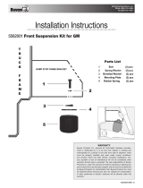
The TMDSEVM6657LS Lite EVM is a single-width, double-height AMC form-factor card developed by
eInfochips. The card enables developers to quickly start evaluating the TMS320C6657 processor and
building applications around it. The EVM also serves as a hardware reference design platform for the
TMS320C6657 DSP.
Figure 1. Block Diagram of TMDXEVM6657LE and TMDSEVM6657LS
2
Using TI's TMS320C6657 Device to Implement Efficient OPUS Codec TIDUA45–June 2015
Solution
Submit Documentation Feedback
Copyright © 2015, Texas Instruments Incorporated

www.ti.com
Design Summary
1.2 Introduction to TI Opus C66x Codec
TI has implemented an Opus encoder and decoder on the C66x platform. This version of the codec has
the following supported features:
• eXpressDSP Digital Media (XDM) interface complaint
• Optimized in Linear ASM, Scheduled ASM, and C implementation with Intrinsic
• Bit-exact with Opus open source standard version 1.1
• Based on Opus coding algorithm for speech and music signals sampled at either 48 KHz, 24 KHz, 16
KHz, 12 KHz, or 8 KHz
• Operates on variable frame sizes of 2.5 ms, 5 ms, 10 ms, 20 ms, 40 ms, and 60 ms
• Supports bit rates ranging from 6 kbps to 510 kbps
• Supports mono and stereo (2) channels at Encoder input and Decoder output
• Supports Forward Error Correction (FEC) at the Encoder
• Supports run-time data buffers relocation and table relocation
• Supports Big Endian and Little Endian modes of operation
• Supports COFF and ELF formats
• Run-time control of the complexity level, supported values from 0 to 10
• Run-time control of DTX
• Supports RTP payload format specified in by the reference C code (RFC 6716)
• Supports packet loss concealment as specified by the reference C code
• Validated on the TMS320C6678 device EVM using Code Composer Studio version 5.2 with the code
generation tools version 7.3.2
The performance of a TI-optimized Opus codec (for the C66x DSP core) in Little Endian mode is shown in
Table 1. There is only a trivial difference between this and Big Endian mode.
Table 1. Performance Statistics (in Megacycles/sec) on C66x
Performance Statistics (in Megacycles/sec) on C66x
(1)
Configuration Average Peak
NB MB WB SWB FB NB MB WB SWB FB
Encoder – LE 8.15 10.45 12.72 9.71 15.56 9.81 12.46 14.5 10.63 22.42
Decoder – LE 1.38 1.75 2.32 7.56 16.83 1.7 2.79 2.82 8.91 17.78
Full Duplex –
9.53 12.2 15.04 17.27 32.39 11.51 15.25 17.32 19.54 40.2
LE
(1)
Measured with program and data memory, stack, and I/O buffers in internal Memory (L2 SRAM) and L1P and L1D caches are
thrashed at frame boundaries. Average and peak MCPS measurements can vary by +/-5%. Measured with frame size = 20 ms,
Complexity=3, VBR Enabled, FEC disabled.
The performance of a non-optimized Opus is tested on an ARM A15 with the same test vectors and
configurations. The Opus 1.1 source code is obtained from http://www.opus-codec.org/downloads/ and
compiled into a Linux application (opus_demo) running on the A15 core of TI’s 66AK2H12. The A15 runs
an Ubuntu 14.04 system with 1.0 GHz speed.
Table 2. Performance Statistics (in Megacycles/sec) on ARM A15 Linux
Performance Statistics (in Megacycles/sec) on ARM A15 Linux
Configuration Average Peak
NB MB WB SWB FB NB MB WB SWB FB
Encoder – LE 16.94 23.28 31.27 15.86 26.48 29.1 30.85 45.6 30.8 42.25
Decoder – LE 2.42 3.31 4.68 10.38 16.55 7.95 11.75 12.8 23.3 30.55
Full Duplex –
19.36 26.59 35.95 26.24 43.03 37.05 42.6 58.4 54.1 72.8
LE
Overall, the opus codec running on a TI C66x DSP core has 1.3×-3.4× the performance improvement over
the A15 implementation.
3
TIDUA45–June 2015 Using TI's TMS320C6657 Device to Implement Efficient OPUS Codec
Solution
Submit Documentation Feedback
Copyright © 2015, Texas Instruments Incorporated

Running Opus Codec on TMDSEVM6657LS Lite EVM
www.ti.com
2 Running Opus Codec on TMDSEVM6657LS Lite EVM
This section explains how to prepare the EVM and codec package, how to run the test example, and the
expected result.
2.1 Prepare the EVM
1. First, unpack the EVM from the shipment box, and set the DSP bootmode to no-boot mode by
following the pin setting at
http://processors.wiki.ti.com/index.php/TMDSEVM6657L_EVM_Hardware_Setup. Note that pin1 of
SW3 defines the endianness of the system. Figure 2 illustrates the setting of no-boot mode with Little
Endian, and the test example described in this design uses Little Endian. The customer may also
switch the setting to Big Endian and use the Opus Big Endian package.
Figure 2. Switch Setting for No-Boot, Little Endian Mode
2. Create a CCXML configuration file for the CCS connection; CCS 5.2 or higher should support the
TMS320C6657 device. If not, install the TI KeyStone1 Emupack from http://software-
dl.ti.com/sdoemb/sdoemb_public_sw/bios_mcsdk/latest/index_FDS.html. Also add the GEL file to core
0 from <CCS_INSTALLATION>\ccs_base\emulation\boards\evmc6657l\gel\evmc6657l.gel.
Figure 3. All Connections
4
Using TI's TMS320C6657 Device to Implement Efficient OPUS Codec TIDUA45–June 2015
Solution
Submit Documentation Feedback
Copyright © 2015, Texas Instruments Incorporated

www.ti.com
Running Opus Codec on TMDSEVM6657LS Lite EVM
3. Finally, launch the target and connect to core 0. You should see GEL runs and core 0 is halted:
C66xx_0: GEL Output: Setup_Memory_Map...
C66xx_0: GEL Output: Setup_Memory_Map... Done.
C66xx_0: GEL Output:
Connecting Target...
C66xx_0: GEL Output: DSP core #0
C66xx_0: GEL Output: C6657L GEL file Ver is 1.004
C66xx_0: GEL Output: Global Default Setup...
C66xx_0: GEL Output: Setup Cache...
C66xx_0: GEL Output: L1P = 32K
C66xx_0: GEL Output: L1D = 32K
C66xx_0: GEL Output: L2 = ALL SRAM
C66xx_0: GEL Output: Setup Cache... Done.
C66xx_0: GEL Output: Main PLL (PLL1) Setup ...
C66xx_0: GEL Output: PLL in Bypass ...
C66xx_0: GEL Output: PLL1 Setup for DSP @ 1000.0 MHz.
C66xx_0: GEL Output: SYSCLK2 = 333.3333 MHz, SYSCLK5 = 200.0 MHz.
C66xx_0: GEL Output: SYSCLK8 = 15.625 MHz.
C66xx_0: GEL Output: PLL1 Setup... Done.
C66xx_0: GEL Output: Power on all PSC modules and DSP domains...
C66xx_0: GEL Output: Power on all PSC modules and DSP domains... Done.
C66xx_0: GEL Output: DDR3 PLL (PLL2) Setup ...
C66xx_0: GEL Output: DDR3 PLL Setup... Done.
C66xx_0: GEL Output: DDR3 Init begin (1333 auto)
C66xx_0: GEL Output: XMC Setup ... Done
C66xx_0: GEL Output:
DDR3 initialization is complete.
C66xx_0: GEL Output: DDR3 Init done
C66xx_0: GEL Output: DDR3 memory test... Started
C66xx_0: GEL Output: DDR3 memory test... Passed
C66xx_0: GEL Output: PLL and DDR3 Initialization completed(0) ...
C66xx_0: GEL Output: configSGMIISerdes Setup... Begin
C66xx_0: GEL Output: SGMII SERDES has been configured.
C66xx_0: GEL Output: Enabling EDC ...
C66xx_0: GEL Output: L1P error detection logic is enabled.
C66xx_0: GEL Output: L2 error detection/correction logic is enabled.
C66xx_0: GEL Output: MSMC error detection/correction logic is enabled.
C66xx_0: GEL Output: Enabling EDC ...Done
C66xx_0: GEL Output: Global Default Setup... Done.
Figure 4. Connect to core 0 of DSP
5
TIDUA45–June 2015 Using TI's TMS320C6657 Device to Implement Efficient OPUS Codec
Solution
Submit Documentation Feedback
Copyright © 2015, Texas Instruments Incorporated

Running Opus Codec on TMDSEVM6657LS Lite EVM
www.ti.com
2.2 Install Opus Codec Package and Dependencies
Download and install the latest Opus from http://software-
dl.ti.com/dsps/dsps_public_sw/codecs/C6X_Speech/2_00_000/index_FDS.html.
Check the user guide under
<OPUS_INSTALLATION>INSTALLATION>\packages\ti\sdo\codecs\opusenc\Docs to see what toolsets
are used to build the test application. For example:
Code Composer Studio version 5.2 with the code generation tools version 7.3.2.
This version of the codec has been validated with
SYS/BIOS version 6.33.04.39,
XDC Tools version 3.23.02.47,
XDAIS Tools version 7.22.00.03,
Framework Component (FC) version 3.22.03.09
If you don’t have all the toolsets, download and install them following the links in the user guide. Different
versions of tools may work, but you may occasionally face tool compatibility issues.
2.3 Build the Test Applications
Import the existing CCS projects for the encoder and decoder:
Figure 5. Import Opus Test Application CCS Projects
Because the tools installation paths may differ from what were used when packaging the Opus codec, you
may experience some CCS include path issues, as shown in Figure 6, circled in the red box. Greyed-out
paths must be resolved before building.
6
Using TI's TMS320C6657 Device to Implement Efficient OPUS Codec TIDUA45–June 2015
Solution
Submit Documentation Feedback
Copyright © 2015, Texas Instruments Incorporated

www.ti.com
Running Opus Codec on TMDSEVM6657LS Lite EVM
Figure 6. Check CCS Include Paths
This can be done by editing the Include Options in the project’s Properties to match the installation and
environment:
Figure 7. Resolve the Reference Paths to Installation and Environment
After resolving the correct paths, the project should be able to build. For an encoder project, Encoder.out
and Encoder.map can be found in the packages\ti\sdo\codecs\opusenc\App\Client\Build\Encoder\Debug
folder. For a decoder project, the same output can be found at the same location in the decoder folder.
7
TIDUA45–June 2015 Using TI's TMS320C6657 Device to Implement Efficient OPUS Codec
Solution
Submit Documentation Feedback
Copyright © 2015, Texas Instruments Incorporated

Running Opus Codec on TMDSEVM6657LS Lite EVM
www.ti.com
2.4 Run the Test Applications
Load the DSP executable to core 0 and run.
The encoder takes a configuraion file stored at \App\Client\Test\Testvecs\ All_test_vectors_enc.txt and
runs. The configuration file specifies the test parameters, input vectors, and output reference vectors. You
can edit this file for different test cases. The meaning of the configuration file is explained in the user
guide. The output should appear like this:
[C66xx_0] Test Vector No. 1
Encoder Input : ..\..\..\test\testvecs\Input\sample.wav
Encoder Reference Output :
..\..\..\test\testvecs\Bitstream\sample_audio_48k_mono_128kbps_FB_c3.bit
Encoding 48000 Hz input at 128.000 kb/s in fullband mode with 480-sample frames.
Processing the frame: 1
Peak Cycles : 212971, at frame 1
Processing the frame: 2
Processing the frame: 3
Processing the frame: 4
Peak Cycles : 216889, at frame 4
Processing the frame: 5
Processing the frame: 6
Processing the frame: 7
….
Processing the frame: 457
Processing the frame: 458
Processing the frame: 459
Processing the frame: 460
COMPLETED TESTVECTOR, TOTAL FRAMES. 460
===============================================
END OF ALL TEST VECTORS
===============================================
If a mismatch between the encoder output and the reference is found, an error message is printed:
ENCODER TEST FAILED AT FRAME NO. …
Similarly, you can load the decoder executable to core 0 and run. The decoder takes a configuration file
stored at \App\Client\Test\Testvecs\All_test_vectors_dec.txt. The output should look similar to that below,
and any failures should be printed:
[C66xx_0] Decoding with 48000 Hz output (1 channels)
Processing the frame: 1
Peak Cycles : 176694, at frame 1
Processing the frame: 2
Processing the frame: 3
Processing the frame: 4
Peak Cycles : 181019, at frame 4
Processing the frame: 5
…
Processing the frame: 459
Processing the frame: 460
COMPLETED TESTVECTOR, TOTAL FRAMES. 460
===============================================
END OF ALL TEST VECTORS
===============================================
3 Acknowledgements and References
• TMS320C6655/57 Fixed and Floating-Point Digital Signal Processor Data Manual (SPRS814A)
• TMDXEVM6657L/LE/TMDSEVM6657LS Technical Reference Manual Version 2.1,
https://www.einfochips.com/images/texas_instrument/TI-TMS320C6657-
EVM/C6657%20Lite%20EVM_TechnicalReferenceManual.pdf
• OPUS Encoder/Decoder (v01.00.03) on C66x Data Sheet
8
Using TI's TMS320C6657 Device to Implement Efficient OPUS Codec TIDUA45–June 2015
Solution
Submit Documentation Feedback
Copyright © 2015, Texas Instruments Incorporated

IMPORTANT NOTICE FOR TI REFERENCE DESIGNS
Texas Instruments Incorporated ("TI") reference designs are solely intended to assist designers (“Buyers”) who are developing systems that
incorporate TI semiconductor products (also referred to herein as “components”). Buyer understands and agrees that Buyer remains
responsible for using its independent analysis, evaluation and judgment in designing Buyer’s systems and products.
TI reference designs have been created using standard laboratory conditions and engineering practices. TI has not conducted any
testing other than that specifically described in the published documentation for a particular reference design. TI may make
corrections, enhancements, improvements and other changes to its reference designs.
Buyers are authorized to use TI reference designs with the TI component(s) identified in each particular reference design and to modify the
reference design in the development of their end products. HOWEVER, NO OTHER LICENSE, EXPRESS OR IMPLIED, BY ESTOPPEL
OR OTHERWISE TO ANY OTHER TI INTELLECTUAL PROPERTY RIGHT, AND NO LICENSE TO ANY THIRD PARTY TECHNOLOGY
OR INTELLECTUAL PROPERTY RIGHT, IS GRANTED HEREIN, including but not limited to any patent right, copyright, mask work right,
or other intellectual property right relating to any combination, machine, or process in which TI components or services are used.
Information published by TI regarding third-party products or services does not constitute a license to use such products or services, or a
warranty or endorsement thereof. Use of such information may require a license from a third party under the patents or other intellectual
property of the third party, or a license from TI under the patents or other intellectual property of TI.
TI REFERENCE DESIGNS ARE PROVIDED "AS IS". TI MAKES NO WARRANTIES OR REPRESENTATIONS WITH REGARD TO THE
REFERENCE DESIGNS OR USE OF THE REFERENCE DESIGNS, EXPRESS, IMPLIED OR STATUTORY, INCLUDING ACCURACY OR
COMPLETENESS. TI DISCLAIMS ANY WARRANTY OF TITLE AND ANY IMPLIED WARRANTIES OF MERCHANTABILITY, FITNESS
FOR A PARTICULAR PURPOSE, QUIET ENJOYMENT, QUIET POSSESSION, AND NON-INFRINGEMENT OF ANY THIRD PARTY
INTELLECTUAL PROPERTY RIGHTS WITH REGARD TO TI REFERENCE DESIGNS OR USE THEREOF. TI SHALL NOT BE LIABLE
FOR AND SHALL NOT DEFEND OR INDEMNIFY BUYERS AGAINST ANY THIRD PARTY INFRINGEMENT CLAIM THAT RELATES TO
OR IS BASED ON A COMBINATION OF COMPONENTS PROVIDED IN A TI REFERENCE DESIGN. IN NO EVENT SHALL TI BE
LIABLE FOR ANY ACTUAL, SPECIAL, INCIDENTAL, CONSEQUENTIAL OR INDIRECT DAMAGES, HOWEVER CAUSED, ON ANY
THEORY OF LIABILITY AND WHETHER OR NOT TI HAS BEEN ADVISED OF THE POSSIBILITY OF SUCH DAMAGES, ARISING IN
ANY WAY OUT OF TI REFERENCE DESIGNS OR BUYER’S USE OF TI REFERENCE DESIGNS.
TI reserves the right to make corrections, enhancements, improvements and other changes to its semiconductor products and services per
JESD46, latest issue, and to discontinue any product or service per JESD48, latest issue. Buyers should obtain the latest relevant
information before placing orders and should verify that such information is current and complete. All semiconductor products are sold
subject to TI’s terms and conditions of sale supplied at the time of order acknowledgment.
TI warrants performance of its components to the specifications applicable at the time of sale, in accordance with the warranty in TI’s terms
and conditions of sale of semiconductor products. Testing and other quality control techniques for TI components are used to the extent TI
deems necessary to support this warranty. Except where mandated by applicable law, testing of all parameters of each component is not
necessarily performed.
TI assumes no liability for applications assistance or the design of Buyers’ products. Buyers are responsible for their products and
applications using TI components. To minimize the risks associated with Buyers’ products and applications, Buyers should provide
adequate design and operating safeguards.
Reproduction of significant portions of TI information in TI data books, data sheets or reference designs is permissible only if reproduction is
without alteration and is accompanied by all associated warranties, conditions, limitations, and notices. TI is not responsible or liable for
such altered documentation. Information of third parties may be subject to additional restrictions.
Buyer acknowledges and agrees that it is solely responsible for compliance with all legal, regulatory and safety-related requirements
concerning its products, and any use of TI components in its applications, notwithstanding any applications-related information or support
that may be provided by TI. Buyer represents and agrees that it has all the necessary expertise to create and implement safeguards that
anticipate dangerous failures, monitor failures and their consequences, lessen the likelihood of dangerous failures and take appropriate
remedial actions. Buyer will fully indemnify TI and its representatives against any damages arising out of the use of any TI components in
Buyer’s safety-critical applications.
In some cases, TI components may be promoted specifically to facilitate safety-related applications. With such components, TI’s goal is to
help enable customers to design and create their own end-product solutions that meet applicable functional safety standards and
requirements. Nonetheless, such components are subject to these terms.
No TI components are authorized for use in FDA Class III (or similar life-critical medical equipment) unless authorized officers of the parties
have executed an agreement specifically governing such use.
Only those TI components that TI has specifically designated as military grade or “enhanced plastic” are designed and intended for use in
military/aerospace applications or environments. Buyer acknowledges and agrees that any military or aerospace use of TI components that
have not been so designated is solely at Buyer's risk, and Buyer is solely responsible for compliance with all legal and regulatory
requirements in connection with such use.
TI has specifically designated certain components as meeting ISO/TS16949 requirements, mainly for automotive use. In any case of use of
non-designated products, TI will not be responsible for any failure to meet ISO/TS16949.IMPORTANT NOTICE
Mailing Address: Texas Instruments, Post Office Box 655303, Dallas, Texas 75265
Copyright © 2015, Texas Instruments Incorporated
/