Page is loading ...

EN
Regulation
VM iSystem – AD281
C003674-B
User Guide
300028026-001-03

Contents
1 Safety instructions .....................................................................................4
1.1 General safety instructions .................................4
1.2 Recommendations ................................................5
1.3 Liabilities ...............................................................6
1.3.1 Manufacturer’s liability .............................................6
1.3.2 Installer’s liability .....................................................6
1.3.3 User’s liability ..........................................................7
2 About this manual ......................................................................................8
2.1 Symbols used .......................................................8
2.2 Abbreviations ........................................................8
3 Description ..................................................................................................9
3.1 Description of the keys ........................................9
3.2 Description of the display ..................................10
3.2.1 Key functions .........................................................10
3.2.2 Flame symbol ........................................................10
3.2.3 Solar (If connected) ...............................................10
3.2.4 Operating modes ...................................................11
3.2.5 Domestic Hot Water override ................................11
3.2.6 Other information ..................................................12
4 Operating the appliance ..........................................................................13
4.1 Browsing in the menus ......................................13
4.2 Reading out measured values ...........................14
4.3 Changing the settings ........................................15
4.3.1 Setting the set point temperatures ........................15
4.3.2 Selecting the operating mode ...............................16
4.3.3 Forcing domestic hot water production .................17
4.3.4 Setting the contrast and lighting on the
display ...................................................................17
4.3.5 Setting the time and date ......................................18
4.3.6 Selecting a timer programme ................................18
4.3.7 Customising a timer programme ...........................19
4.3.8 Setting an annual clock .........................................21
1
28/10/2015 - 300028026-001-03

4.4 Installation shutdown .........................................23
4.5 Antifreeze protection ..........................................23
5 Troubleshooting .......................................................................................24
5.1 Messages (type code Mxx) ................................24
5.2 Faults ...................................................................24
6 Warranty ....................................................................................................27
6.1 General ................................................................27
6.2 Warranty terms ...................................................27
7 Appendix - Information on the Ecodesign and Energy Labelling
Directives ..................................................................................................28
Contents
2
28/10/2015 - 300028026-001-03

3
28/10/2015 - 300028026-001-03

1 Safety instructions
1.1 General safety instructions
DANGER
This appliance can be used by children aged
from 8 years and above and persons with
reduced physical, sensory or mental capabilities
or lack of experience and knowledge if they have
been given supervision or instruction concerning
use of the appliance in a safe way and
understand the hazards involved. Children shall
not play with the appliance. Cleaning and user
maintenance shall not be made by children
without supervision.
The user guide and the installation manual can
also be found on our internet site.
CAUTION
Allowance must be made for a means of
disconnection in the fixed pipes in accordance
with the regulations on installations.
CAUTION
If a power cord is provided with the appliance
and it turns out to be damaged, it must be
replaced by the manufacturer, its after sales
service or persons with similar qualifications in
order to obviate any danger.
CAUTION
Respect the maximum water inlet pressure to
ensure correct operation of the appliance,
referring to the chapter "Technical
Specifications".
CAUTION
Before any work, switch off the mains supply to
the appliance.
VM iSystem – AD281 1. Safety instructions
28/10/2015 - 300028026-001-03
4

CAUTION
Any operation on the installation must be
performed by a qualified technician respecting
professional regulations and in accordance with
this document.
CAUTION
Solar installations must be earthed to protect
them against lightning.
CAUTION
Operation of the thermostatic mixing valve on
the solar hot water tank outlet must be checked
on commissioning of the solar system.
CAUTION
Use only original spare parts.
CAUTION
Before any work, switch off the mains supply to
the appliance. Protect the installation against
any unwanted restarts.
1.2 Recommendations
CAUTION
Do not neglect to service the appliance. Service
the appliance regularly to ensure that it operates
correctly.
WARNING
Only qualified professionals are authorised to
work on the appliance and the installation.
WARNING
Heating water and domestic water must not
come into contact with each other. Domestic
water must not circulate via the exchanger.
4 To take advantage of the guarantee, no modifications
must be made to the appliance.
4 To reduce heat losses as much as possible, insulate
the pipes.
1. Safety instructions
VM iSystem – AD281
5
28/10/2015 - 300028026-001-03

Casing components
Only remove the casing for maintenance and repair
operations. Put the casing back in place after
maintenance and repair operations.
Instructions stickers
The instructions and warnings affixed to the appliance
must never be removed or covered and must remain
legible during the entire lifespan of the appliance.
Immediately replace damaged or illegible instructions and
warning stickers.
1.3 Liabilities
1.3.1. Manufacturer’s liability
Our products are manufactured in compliance with the
requirements of the various applicable European
Directives. They are therefore delivered with [ marking
and all relevant documentation.
In the interest of customers, we are continuously
endeavouring to make improvements in product quality.
All the specifications stated in this document are therefore
subject to change without notice.
Our liability as the manufacturer may not be invoked in the
following cases:
4 Failure to abide by the instructions on using the
appliance.
4 Faulty or insufficient maintenance of the appliance.
4 Failure to abide by the instructions on installing the
appliance.
1.3.2. Installer’s liability
The installer is responsible for the installation and
commissioning of the appliance. The installer must
respect the following instructions:
4 Read and follow the instructions given in the manuals
provided with the appliance.
4 Carry out installation in compliance with the prevailing
legislation and standards.
4 Perform the initial start up and carry out any checks
necessary.
VM iSystem – AD281
1. Safety instructions
28/10/2015 - 300028026-001-03
6

4 Explain the installation to the user.
4 If a maintenance is necessary, warn the user of the
obligation to check the appliance and maintain it in
good working order.
4 Give all the instruction manuals to the user.
1.3.3. User’s liability
To guarantee optimum operation of the appliance, the
user must respect the following instructions:
4 Read and follow the instructions given in the manuals
provided with the appliance.
4 Call on qualified professionals to carry out installation
and initial start up.
4 Get your installer to explain your installation to you.
4 Ensure the Appliance is serviced in accordance with
the manufacturer’s instructions by a suitable qualified
person.
4 Keep the instruction manuals in good condition close
to the appliance.
1. Safety instructions VM iSystem – AD281
7
28/10/2015 - 300028026-001-03

2 About this manual
2.1 Symbols used
In these instructions, various danger levels are employed to draw the
user’s attention to particular information. In so doing, we wish to
safeguard the user’s safety, highlight hazards and guarantee correct
operation of the appliance.
DANGER
Risk of a dangerous situation causing serious physical
injury.
WARNING
Risk of a dangerous situation causing slight physical
injury.
CAUTION
Risk of material damage.
Signals important information.
¼Signals a referral to other instructions or other pages in the
instructions.
2.2 Abbreviations
4 DHW: Domestic hot water
4 3WV: 3-way valve
VM iSystem – AD281 2. About this manual
28/10/2015 - 300028026-001-03
8

3 Description
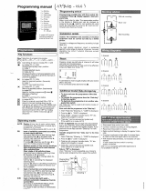
3.1 Description of the keys
A
Temperature setting key (heating, DHW, swimming pool)
B
Operating mode selection key
C
DHW override key
D
Key to access the parameters reserved for the installer
E
Keys on which the function varies as and when selections
are made
F
Rotary setting button:
4 Turn the rotary button to scroll through the menus or
modify a value
4 Press the rotary button to access the selected menu
or confirm a value modification
G
Button AUTO/MANU
H
Fuse
J
Button ON/OFF
C003672-B
bar
STD
0 2 4 6 8 10 12 14 16 18 22 2420
AUTO
A
B
C
D
E
F
J
H
G
3. Description VM iSystem – AD281
9
28/10/2015 - 300028026-001-03

3.2 Description of the display
3.2.1. Key functions
>
Access to the various menus
(
Used to scroll through the menus
’
Used to scroll through the parameters
?
The symbol is displayed when help is available
f
Used to display the curve of the parameter selected
STD
Reset of the time programmes
b
Selection of comfort mode or selection of the days to be
programmed
v
Selection of reduced mode or deselection of the days to
be programmed
j
Back to the previous level
ESC
Back to the previous level without saving the
modifications made
3.2.2. Flame symbol
4 The symbol is displayed: The burner is operating.
4 The symbol is not displayed: The burner is off.
3.2.3. Solar (If connected)
u
The solar load pump is running
L000200-A
The top part of the tank is reheated to the tank set point
L000201-A
The entire tank is reheated to the tank set point
L000198-A
The entire tank is reheated to the solar tank set point
L000199-A
The tank is not loaded - Presence of the solar control
system
bar
r
STD
(
'
t
0 2 4 6 8 10 12 14 16 18 22 2420
C002696-A
p
b
AUTO
x
c
r
j
L
g
m
bar
STD
t
0 2 4 6 8 10 12 14 16 18 22 2420
C002701-B
p
b
AUTO
x
c
r
j
M
g
m
bar
STD
t
0 2 4 6 8 10 12 14 16 18 22 2420
L000197-A
p
b
AUTO
x
c
r
j
M
g
m
VM iSystem – AD281 3. Description
28/10/2015 - 300028026-001-03
10

3.2.4. Operating modes
p
Summer mode: The heating is off. Domestic hot water
continues to be produced
b
WINTER mode: Heating and domestic hot water working
AUTO
Operation in automatic mode according to the timer
programme
x
Comfort mode: The symbol is displayed when a DAY
override (comfort) is activated
4 Flashing symbol: Temporary override
4 Steady symbol: Permanent override
m
Reduced mode: The symbol is displayed when a NIGHT
override (reduced) is activated
4 Flashing symbol: Temporary override
4 Steady symbol: Permanent override
g
Holiday mode: The symbol is displayed when a HOLIDAY
override (antifreeze) is activated
4 Flashing symbol: Holiday mode programmed
4 Steady symbol: Holiday mode active
m
Manual mode: The boiler operates with the displayed set
point. All of the pumps operate. The 3-way valves are not
controlled.
3.2.5. Domestic Hot Water override
A bar is displayed when a DHW override is activated:
4 Flashing bar: Temporary override
4 Steady bar: Permanent override
bar
STD
t
0 2 4 6 8 10 12 14 16 18 22 2420
C002697-B
p
b
AUTO
x
c
r
j
M
g
m
bar
STD
t
0 2 4 6 8 10 12 14 16 18 22 2420
C002698-B
p
b
AUTO
x
c
r
j
M
g
m
bar
STD
t
0 2 4 6 8 10 12 14 16 18 22 2420
C002707-A
p
b
AUTO
x
c
r
j
M
g
m
3. Description VM iSystem – AD281
11
28/10/2015 - 300028026-001-03

3.2.6. Other information
r
The symbol is displayed when domestic hot water
production is running.
w
Valve indicator: The symbol is displayed when a 3-way
valve is connected.
4 x: 3-way valve opens
4 c: 3-way valve closes
M
The symbol is displayed when the pump is operating.
Name of the circuit for which the parameters are
displayed.
bar
STD
t
0 2 4 6 8 10 12 14 16 18 22 2420
C002699-B
p
b
AUTO
x
c
r
j
M
g
m
VM iSystem – AD281 3. Description
28/10/2015 - 300028026-001-03
12

4 Operating the appliance
4.1 Browsing in the menus
1. To select the desired menu, turn the rotary button.
2. To access the menu, press the rotary button.
To go back to the previous display, press the key
j
.
3. To select the desired parameter, turn the rotary button.
4. To modify the parameter, press the rotary button.
To go back to the previous display, press the key
j
.
5. To modify the parameter, turn the rotary button.
6. To confirm, press the rotary button.
To cancel, press key
h
.
7. To go back to the main display, press key
j
2 times.
It is possible to use the ( and ’ keys instead of the rotary
button.
bar
1
1
2
2
r
c
STD
(
'
t
v
0 2 4 6 8 10 12 14 16 18 22 2420
p
b
AUTO
x
c
r
j
L
g
m
#MEASURES
#CHOICE TIME PROG.
#TIME PROGRAM
#SETTING
#TIME .DAY
a
C002220-B-04
bar
1
1
2
2
r
c
STD
(
'
t
v
0 2 4 6 8 10 12 14 16 18 22 2420
p
b
AUTO
x
c
r
j
L
g
m
CURRENT PROG.B
CURRENT PROG.C
P2
P3
a
C002221-C-04
bar
1
1
2
2
r
c
STD
(
'
t
v
0 2 4 6 8 10 12 14 16 18 22 2420
p
b
AUTO
x
c
r
j
L
g
m
CURRENT PROG.C
"Choice of the timeprogram
applied C"
P4
a
C002222-C-04
bar
1
1
2
2
r
c
STD
(
'
t
v
0 2 4 6 8 10 12 14 16 18 22 2420
p
b
AUTO
x
c
r
j
M
g
m
LUNDI 11:45
C002224-D-04
2x
4. Operating the appliance VM iSystem – AD281
13
28/10/2015 - 300028026-001-03

4.2 Reading out measured values
The various values measured by the appliance are displayed in the
#MEASURES menu.
1. To access user level: Press the
>
key.
2. Select the menu #MEASURES.
4 Turn the rotary button to scroll through the menus or
modify a value.
4 Press the rotary button to access the selected menu
or confirm a value modification.
¼
For a detailed explanation of menu browsing, refer to
the chapter: "Browsing in the menus", page 13.
User level - #MEASURES menu
Parameter Description Unit
OUTSIDE TEMP.
Outside temperature °C
ROOMTEMP.B
(1)
Room temperature of circuit B °C
ROOMTEMP.C
(1)
Room temperature of circuit C °C
BOILER TEMP
(2)
Water temperature in the boiler °C
WATER TEMP.
(1)
Water temperature in the DHW tank °C
STOR.TANK.TEMP
(1)
Water temperature in the storage tank °C
SWIMMING P.T.B
(1)
Water temperature of the swimming pool on circuit B °C
SWIMMING P.T.C
(1)
Water temperature of the swimming pool on circuit C °C
OUTLET TEMP.B
(1)
Temperature of the flow water in circuit B °C
OUTLET TEMP.C
(1)
Temperature of the flow water in circuit C °C
TEMP.SYSTEM
(1)
Temperature of the system flow water if multi-generator °C
T.DHW BOTTOM
(1)
Water temperature in the bottom of the DHW tank °C
TEMP.TANK AUX
(1)
Water temperature in the second DHW tank connected to the AUX circuit °C
TEMP.SOL.TANK
(1)(2)
Temperature of the hot water produced by solar power (TS) °C
SOLAR.COLL.T.
(1)
(2)
Solar panel temperature (TC) °C
SOLA.ENERGY
(1)
(2)
Solar energy accumulated in the tank kWh
IN 0-10V
(1)(2)
Voltage at input 0-10 V V
CTRL Software control number
(1) The parameter is only displayed for the options, circuits or sensors actually connected.
(2) According to the configuration
bar
1
1
2
2
r
c
STD
(
'
t
v
0 2 4 6 8 10 12 14 16 18 22 2420
p
b
AUTO
x
c
r
j
M
g
m
SUNDAY 11:45
C002219-D-04
VM iSystem – AD281 4. Operating the appliance
28/10/2015 - 300028026-001-03
14

4.3 Changing the settings
4.3.1. Setting the set point temperatures
To set the various heating, DHW and swimming pool temperatures,
proceed as follows:
1. Press the
C
key.
2. To select the desired parameter, turn the rotary button.
3. To modify the parameter, press the rotary button.
To go back to the previous display, press the key
j
.
4. To modify the parameter, turn the rotary button.
5. To confirm, press the rotary button.
To cancel, press key
h
.
C Menu
Parameter Adjustment range Description Factory setting
DAY TEMP.B
(1)
5 to 30 °C Desired room temperature in comfort periods on circuit B 20 °C
NIGHT TEMP.B
(1)
5 to 30 °C Desired room temperature in reduced periods on circuit B 16 °C
DAY TEMP.C
(1)
5 to 30 °C Desired room temperature in comfort periods on circuit C 20 °C
NIGHT TEMP.C
(1)
5 to 30 °C Desired room temperature in reduced periods on circuit B 16 °C
TEMP.SOL.TANK
(1)
20 to 80 °C Maximum load temperature of the tank’s solar zone 60°C
DHW TEMP.
(1)
10 to 80 °C Desired domestic hot water temperature in the DHW circuit 55 °C
TEMP.TANK AUX
(1)
10 to 80 °C Desired domestic hot water temperature in the auxiliary circuit 55 °C
SWIMMING P.T.B
(1)
5 to 39 °C Desired temperature for swimming pool B 20 °C
SWIMMING P.T.C
(1)
5 to 39 °C Desired temperature for swimming pool C 20 °C
(1) The parameter is only displayed for the options, circuits or sensors actually connected.
MODE
C002266-A
4. Operating the appliance VM iSystem – AD281
15
28/10/2015 - 300028026-001-03

4.3.2. Selecting the operating mode
To select an operating mode, proceed as follows:
1. Press the MODE key.
2. To select the desired parameter, turn the rotary button.
3. To modify the parameter, press the rotary button.
To go back to the previous display, press the key
j
.
4. To modify the parameter, turn the rotary button.
5. To confirm, press the rotary button.
To cancel, press key
h
.
MODE Menu
Parameter Adjustment range Description Factory setting
AUTOMATIQUE
The comfort ranges are determined by the timer programme.
DAY
7/7, xx:xx Comfort mode is forced until the time indicated or all the time (7/7). Present time + 1
hour
NIGHT
7/7, xx:xx Reduced mode is forced until the time indicated or all the time
(7/7).
Present time + 1
hour
HOLIDAYS
7/7, 1 to 364 The antifreeze mode is active on all boiler circuits.
Number of days’ holiday: xx
(1)
heating OFF: xx:xx
(1)
Restarting: xx:xx
(1)
Present date + 1
day
SUMMER
The heating is off.
Domestic hot water continues to be produced.
MANUEL
The generator operates according to the set point setting. All of
the pumps operate. Option of setting the set point by simply
turning the rotary button.
FORCE AUTO
(2)
YES / NO An operating mode override is activated on the remote control
(option).
To force all circuits to run on AUTOMATIQUE mode, select
YES.
(1) The start and end days and the number of days are calculated in relation to each other.
(2) The parameter is only displayed if a room sensor is connected.
MODE
C002267-A
VM iSystem – AD281 4. Operating the appliance
28/10/2015 - 300028026-001-03
16

4.3.3. Forcing domestic hot water production
To force domestic hot water production, proceed as follows:
1. Press the
r
key.
2. To select the desired parameter, turn the rotary button.
3. To modify the parameter, press the rotary button.
To go back to the previous display, press the key
j
.
4. To modify the parameter, turn the rotary button.
5. To confirm, press the rotary button.
To cancel, press key
h
.
r Menu
Parameter Description Factory setting
AUTOMATIQUE
The domestic hot water comfort ranges are determined by the timer programme.
COMFORT
Domestic hot water comfort mode is forced until the time indicated or all the time (7/7). Present time + 1 hour
4.3.4. Setting the contrast and lighting on the
display
1. To access user level: Press the
>
key.
2. Select the menu #SETTING.
4
Turn the rotary button to scroll through the menus or
modify a value.
4 Press the rotary button to access the selected menu
or confirm a value modification.
¼
For a detailed explanation of menu browsing, refer to
the chapter: "Browsing in the menus", page 13.
3. Set the following parameters:
User level - #SETTING Menu
Parameter Adjustment range Description Factory setting Customer setting
CONTRAST DISP.
Adjusting the display contrast.
BACK LIGHT COMFORT
The screen is illuminated continuously in
daytime periods.
ECO
ECO
The screen is illuminated for 2 minutes
whenever pressed.
MODE
C002268-A
bar
1
1
2
2
r
c
STD
(
'
t
v
0 2 4 6 8 10 12 14 16 18 22 2420
p
b
AUTO
x
c
r
j
M
g
m
SUNDAY 11:45
C002219-D-04
4. Operating the appliance VM iSystem – AD281
17
28/10/2015 - 300028026-001-03

4.3.5. Setting the time and date
1. To access user level: Press the
>
key.
2. Select the menu #TIME .DAY.
4 Turn the rotary button to scroll through the menus or
modify a value.
4 Press the rotary button to access the selected menu
or confirm a value modification.
¼
For a detailed explanation of menu browsing, refer to
the chapter: "Browsing in the menus", page 13.
3. Set the following parameters:
User level - #TIME .DAY Menu
(1)
Parameter Adjustment range Description Factory setting Customer setting
HOURS
0 to 23 Hours setting
MINUTE
0 to 59 Minutes setting
DAY
Monday to Sunday Setting the day of the week
DATE
1 to 31 Day setting
MONTH
January to December Month setting
YEAR
2008 to 2099 Year setting
SUM.TIME AUTO
automatic switch to summer time on the last Sunday
in March and back to winter time on the last Sunday
in October.
AUTO
MANU
for countries where the time change is done on other
dates or is not in use.
(1) According to the configuration
4.3.6. Selecting a timer programme
1. To access user level: Press the
>
key.
2. Select the menu #CHOICE TIME PROG..
4
Turn the rotary button to scroll through the menus or
modify a value.
4 Press the rotary button to access the selected menu
or confirm a value modification.
¼
For a detailed explanation of menu browsing, refer to
the chapter: "Browsing in the menus", page 13.
3. To select the desired parameter.
User level -
#CHOICE TIME PROG. Menu
Parameter Adjustment range Description
CURRENT PROG.B
P1 / P2 / P3 / P4 Comfort programme activated
(Circuit B)
CURRENT PROG.C
P1 / P2 / P3 / P4 Comfort programme activated
(Circuit C)
4. Assign the desired timer programme (P1 to P4) to the circuit with
the rotary button.
bar
1
1
2
2
r
c
STD
(
'
t
v
0 2 4 6 8 10 12 14 16 18 22 2420
p
b
AUTO
x
c
r
j
M
g
m
SUNDAY 11:45
C002219-D-04
bar
1
1
2
2
r
c
STD
(
'
t
v
0 2 4 6 8 10 12 14 16 18 22 2420
p
b
AUTO
x
c
r
j
M
g
m
SUNDAY 11:45
C002219-D-04
VM iSystem – AD281
4. Operating the appliance
28/10/2015 - 300028026-001-03
18

4.3.7. Customising a timer programme
1. To access user level: Press the
>
key.
2. Select the menu #TIME PROGRAM.
4 Turn the rotary button to scroll through the menus or
modify a value.
4 Press the rotary button to access the selected menu
or confirm a value modification.
¼
For a detailed explanation of menu browsing, refer to
the chapter: "Browsing in the menus", page 13.
3. To select the desired parameter.
User level - #TIME PROGRAM Menu
Parameter Time schedule Description
TIME PROG.B PROG P2 B
PROG P3 B
PROG P4 B
Timer programme for circuit B
TIME PROG.C PROG P2 C
PROG P3 C
PROG P4 C
Timer programme for circuit C
TIME PROG.DHW
DHW circuit timer programme
TIME PROG.AUX
Auxiliary circuit timer programme
4. To select a timer programme to be modified.
5.
To select to days for which the timer programme is to be
modified:
Turn the rotary button to the left until you reach the day desired.
To confirm, press the rotary button.
6.
b
: Day selection
Press key
b
/
v
until the symbol
b
is displayed.
Turn the rotary button to the right to select the day(s) desired.
v
: Cancelling the day selection
Press key
b
/
v
until the symbol
v
is displayed.
Turn the rotary button to the right to cancel selection of the relevant
day(s).
7. When the days desired for the programme have been selected,
press the rotary button to confirm.
bar
1
1
2
2
r
c
STD
(
'
t
v
0 2 4 6 8 10 12 14 16 18 22 2420
p
b
AUTO
x
c
r
j
M
g
m
SUNDAY 11:45
C002219-D-04
bar
1
1
2
2
r
c
STD
(
'
t
v
0 2 4 6 8 10 12 14 16 18 22 2420
p
b
AUTO
x
c
r
j
L
g
m
PROG P2 C
Mo Tu We Th Fr Sa Su
"Display of the timeprogram.
To continuepush on the button"
a
C002228-B-04
bar
1
1
2
2
r
c
STD
(
'
t
v
0 2 4 6 8 10 12 14 16 18 22 2420
p
b
AUTO
x
c
r
j
L
g
m
PROG P2 C
Mo Tu
We Th Fr Sa Su
"Select the days to
program"
a
C002229-C-04
4. Operating the appliance
VM iSystem – AD281
19
28/10/2015 - 300028026-001-03
/