Page is loading ...

Thank you for buying this energy efcient water heater.
We appreciate your condence in our products.
PRINTED 1215 329762-001
PLACE THESE INSTRUCTIONS ADJACENT TO HEATER AND NOTIFY OWNER TO KEEP FOR FUTURE REFERENCE.
COMMERCIAL ELECTRIC WATER HEATER
MODELS SEV-150 THRU SEV-10000
SEH-200 THRU SEH-10000
INSTALLATION - OPERATION - SERVICE
MAINTENANCE - LIMITED WARRANTY
Instruction Manual
Read and understand this instruction
manual and the safety messages
herein before installing, operating or
servicing this water heater.
Failure to follow these instructions and
safety messages could result in death
or serious injury.
This manual must remain with the
water heater.
If the heater becomes immersed in water up to or
above the level of the bottom of the element doors,
the heater should be examined by a qualified service
agency before it is placed in operation, see Page 2.
LOW LEAD
CONTENT
500 Tennessee Waltz Parkway
Ashland City, TN 37015

2
TABLE OF CONTENTS
This manual contains the operating instructions for the commercial electric Xi control. It is intended to be used in conjunction with
the water heater instruction manual.
TABLE OF CONTENTS ........................................................2
SAFE INSTALLATION, USE AND SERVICE .........................3
Important Denitions ........................................................3
GENERAL SAFETY INFORMATION .....................................4
Precautions .....................................................................4
Hydrogen Gas (Flammable) .............................................4
GENERAL SAFETY INFORMATION .....................................5
APPROVALS ........................................................................6
MODEL AND RATING ..........................................................6
INTRODUCTION ..................................................................7
Abbreviations Used .........................................................7
Preparing for the Installation ............................................7
DIMENSIONS AND CAPACITIES DATA ................................8
FEATURES AND COMPONENTS ........................................9
FEATURES AND COMPONENTS ......................................10
LOCATING THE NEW WATER HEATER ............................ 11
Facts to Consider About the Location ............................ 11
REQUIRED ABILITY ...................................................... 11
General ......................................................................... 11
Chemical Vapor Corrosion ............................................. 11
INSTALLATION .................................................................. 11
Circulating Pump ...........................................................12
Insulation Blankets ........................................................12
Temperature-Pressure Relief Valve ...............................12
Closed Water Systems ..................................................13
Thermal Expansion ........................................................13
ELECTRICAL .....................................................................13
General .........................................................................13
Branch Circuit ................................................................13
Heater Circuits ..............................................................13
ELECTRICAL AND RECOVERIES DATA ............................14
Control Circuits ..............................................................14
Power Circuit .................................................................14
WIRING DIAGRAMS ..........................................................15
OPERATION ......................................................................18
General .........................................................................18
Initial Start Up................................................................18
Draining The Water Heater ............................................18
TEMPERATURE REGULATION .........................................19
High Temperature Limit Controls (Eco) ..........................19
Thermostat Controls ......................................................19
Temperature Adjustment ................................................19
CONTROL SYSTEM OPERATION .....................................20
MAINTENANCE .................................................................32
General .........................................................................32
TROUBLESHOOTING CHECKLIST ...................................35
WARRANTY .......................................................................36
NOTES ..........................................................................37-39

3
SAFE INSTALLATION, USE AND SERVICE
IMPORTANT DEFINITIONS
• QualiedInstallerorServiceAgency:
Installation and service of this water heater requires ability equivalent to that of a Qualied Agency (as dened by ANSI below) in
the eld involved. Installation skills such as plumbing and electrical supply are required in addition to electrical testing skills when
performing service.
• ANSIZ223.12006Sec.3.3.83:
“Qualied Agency” - “Any individual, rm, corporation or company that either in person or through a representative is engaged in and is
responsible for (a) the installation, testing or replacement of gas piping or (b) the connection, installation, testing, repair or servicing of
appliances and equipment; that is experienced in such work; that is familiar with all precautions required; and that has complied with all
the requirements of the authority having jurisdiction.”
The proper installation, use and servicing of this water heater is extremely important to your safety and the safety of others.
Many safety-related messages and instructions have been provided in this manual and on your own water heater to warn you and
others of a potential injury hazard. Read and obey all safety messages and instructions throughout this manual. It is very important
that the meaning of each safety message is understood by you and others who install, use, or service this water heater.
DANGER indicates an imminently
hazardous situation which, if not avoided,
will result in injury or death.
This is the safety alert symbol. It is used to alert you to
potential personal injury hazards. Obey all safety
messages that follow this symbol to avoid possible
injury or death.
WARNING indicates a potentially hazardous
situation which, if not avoided, could result
in injury or death.
CAUTION indicates a potentially hazardous
situation which, if not avoided, could result in
minor or moderate injury.
CAUTION used without the safety alert
symbol indicates a potentially hazardous
situation which, if not avoided, could result in
property damage.
WARNING
CAUTION
CAUTION
DANGER
All safety messages will generally tell you about the type of hazard, what can happen if you do not follow the safety message, and
how to avoid the risk of injury.

4
GENERAL SAFETY INFORMATION
Whenservicingthisunit,verifythepowertotheunitisturnedoffpriortoopeningthecontrolcabinetdoor.
PRECAUTIONS
DO NOT USE THIS APPLIANCE IF ANY PART HAS BEEN
EXPOSED TO FLOODING OR WATER DAMAGE. Immediately
call a qualied service technician to inspect the appliance and to
replace any part of the control system which has been under water.
If the unit is exposed to the following, do not operate heater until all
corrective steps have been made by a qualied service technician.
1. External re.
2. Damage.
3. Firing without water.
GROUNDING INSTRUCTIONS
This water heater must be grounded in accordance with the National
Electrical Code and/or local codes. These must be followed in all
cases. Failure to ground this water heater properly may also cause
erratic control system operation on ELECTRONIC CONTROL models.
This water heater must be connected to a grounded metal, permanent
wiring system, or an equipment grounding conductor must be run with
the circuit conductors and connected to the equipment grounding
terminal or lead on the water heater.
HYDROGEN GAS (FLAMMABLE)
Explosion Hazard
Flammable hydrogen gases may
be present.
Keep all ignition sources away
from faucet when turning on
hot water.
Hydrogen gas can be produced in a hot water system
served by this
heater that has not been used for a long period of time (generally two weeks
or more).
Hydrogen gas is extremely ammable. To reduce risk of injury
under these conditions, it is recommended that the hot water faucet be
opened for several minutes at the kitchen sink before using any electrical
appliance connected to the hot water system. If hydrogen is present there
will probably be an unusual sound such as air escaping through the
pipe as water begins to ow. THERE SHOULD BE NO SMOKING OR
OPEN FLAME NEAR THE FAUCET AT THE TIME IT IS OPEN.
Improper installation, use and service may
result in property damage.
CAUTION
• Do not operate water heater if any part has been
exposed to flooding or water damage.
•
Inspect anode rods regularly, replace when significantly depleted.
• Install in location with drainage.
• Fill tank with water before operation.
• Properly sized thermal expansion tanks are required on all
closed water systems.
Refer to this manual for installation and service.
Explosion Hazard
Flammable hydrogen gases may
be present.
Keep all ignition sources away
from faucet when turning on
hot water.
Read and understand this instruction
manual and the safety messages
herein before installing, operating or
servicing this water heater.
Failure to follow these instructions and
safety messages could result in death
or serious injury.
This manual must remain with the
water heater.
Explosion Hazard
Overheated water can cause
water tank explosion.
Properly sized temperature
and pressure relief valve must
be installed in opening provided.
Before removing any access
panels or servicing the water
heater, make sure the electrical
supply to the water heater is
turned “OFF”.
Failure to do this could result in
death, serious bodily injury, or
property damage.
Water temperature over 125°F (52°C)
can cause severe burns instantly
resulting in severe injury or death.
Children, the elderly and the physically
or mentally disabled are at highest risk
for scald injury.
Feel water before bathing or showering.
Temperature limiting devices such as
mixing valves must be installed when
required by codes and to ensure safe
temperatures at fixtures.
DANGER

5
GENERAL SAFETY INFORMATION
Whenservicingthisunit,verifythepowertotheunitisturnedoffpriortoopeningthecontrolcabinetdoor.
Read and understand this instruction
manual and the safety messages
herein before installing, operating or
servicing this water heater.
Failure to follow these instructions and
safety messages could result in death
or serious injury.
This manual must remain with the
water heater.
Explosion Hazard
Overheated water can cause
water tank explosion.
Properly sized temperature
and pressure relief valve must
be installed in opening provided.
Before removing any access
panels or servicing the water
heater, make sure the electrical
supply to the water heater is
turned “OFF”.
Failure to do this could result in
death, serious bodily injury, or
property damage.
Water temperature over 125°F (52°C)
can cause severe burns instantly
resulting in severe injury or death.
Children, the elderly and the physically
or mentally disabled are at highest risk
for scald injury.
Feel water before bathing or showering.
Temperature limiting devices such as
mixing valves must be installed when
required by codes and to ensure safe
temperatures at fixtures.
DANGER
Improper installation, use and service may
result in property damage.
CAUTION
• Do not operate water heater if any part has been
exposed to flooding or water damage.
•
Inspect anode rods regularly, replace when significantly depleted.
• Install in location with drainage.
• Fill tank with water before operation.
• Properly sized thermal expansion tanks are required on all
closed water systems.
Refer to this manual for installation and service.

6
APPROVALS
MODEL AND RATING
All models are listed
by Underwriters
Laboratories Inc.
LOW LEAD
CONTENT

7
INTRODUCTION
Thank You for purchasing this water heater. Properly installed
and maintained, it should give you years of trouble free service.
ABBREVIATIONS USED
Abbreviations found in this Instruction Manual include :
• ANSI - American National Standards Institute
• ASME - American Society of Mechanical Engineers
• NEC - National Electrical Code
• NFPA - National Fire Protection Association
• UL - Underwriters Laboratory
• CSA - Canadian Standards Association
• AHRI - Air Condition, Heating and Refrigeration Institute
PREPARING FOR THE INSTALLATION
Before removing any access
panels or servicing the water
heater, make sure the electrical
supply to the water heater is
turned “OFF”.
Failure to do this could result in
death, serious bodily injury, or
property damage.
1. Read the “General Safety” section of this manual first and
then the entire manual carefully. If you don’t follow the
safety rules, the water heater may not operate safely.
It could cause DEATH, SERIOUS BODILY INJURY AND/OR
PROPERTY DAMAGE.
This manual contains instructions for the installation, operation,
and maintenance of the water heater. It also contains warnings
throughout the manual that you must read and be aware of.
All warnings and all instructions are essential to the proper
operation of the water heater and your safety. READ THE
ENTIRE MANUAL BEFORE ATTEMPTING TO INSTALL OR
OPERATE THE WATER HEATER.
General outline diagrams are in this manual. These
diagrams will serve to provide the installer with a reference
for basic installation of this product. IT IS NECESSARY
THAT ALL WATER PIPING AND THE ELECTRICAL
WIRING BE INSTALLED AND CONNECTED AS SHOWN IN
THE DIAGRAMS.
Be sure to turn off power when working on or near the
electrical system of the water heater. Never touch electrical
components with wet hands or when standing in water. When
replacing fuses always use the correct size for the circuit.
Use same size and type of fuse when replacing.
Detailed installation diagrams are in this manual. These
diagrams will serve to provide the installer with a reference
for the materials and method of piping suggested. IT
IS NECESSARY THAT ALL WATER PIPING AND THE
ELECTRICAL WIRING BE INSTALLED AND CONNECTED
AS SHOWN IN THE DIAGRAMS.
The principal components of the heater are identied on pages 9
and 10. The model and rating plate on page 7 interprets certain
markings into useful information. Both of these references
should be used to identify the heater, its components and
optional equipment.
2. The installation must conform with these instructions and the
local code authority having jurisdiction and the requirements
of the power company. In the absence of local codes, the
installation must comply with the current editions of the
National Electrical Code, NFPA 70 or the Canadian Electrical
Code CSA C22.1. The National Electrical Code may be ordered
from: National Fire Protection Association, 1 Batterymarch
Park, Quincy, MA 02269. The Canadian Electrical Code is
available from the Canadian Standards Association, 8501
East Pleasant Valley Road, Cleveland, OH 44131.
3. If after reading this manual you have any questions or do not
understand any portion of the instructions, call the toll free
number on the back cover for further assistance.
A sample rating plate and barcode tag are shown on page
6 of this manual. In order to expedite your request, please
have the serial number and item ID from the barcode tag
available for the technician.
4. Carefully plan your intended placement of the water heater.
Examine the location to ensure the water heater complies with
the “Locating the New Water Heater” section in this manual.
Clearance must be maintained so that the coil bundle may
be removed for servicing after installation.
Installation and service of this water heater requires ability
equivalent to that of a licensed tradesman or qualified agency
(page 3) in the field involved. Plumbing and electrical work
are required.
5. For installation in California this water heater must be braced or
anchored to avoid falling or moving during an earthquake. See
instructions for correct installation procedures. Instructions
may be obtained from California Ofce of the State Architect,
1102 Q Street, Suite 5100, Sacramento, CA 95811.
6. Massachusetts Code requires this water heater to be
installed in accordance with Massachusetts 248-CMR 2.00:
State Plumbing Code and 248-CMR 5.00.

8
DIMENSIONS AND CAPACITIES DATA
ALL DIMENSIONS IN INCHES
Model*
Nominal
Gallon
Capacity
Maximum
KW Input
Height
A
Width
(Length)
B
Depth
C D E
Skid
Spacing
F
Inspection
Opening
G
Inlet
Outlet
Opening
Drain
Opening
Relief
Valve
Opening**
HORIZONTAL ELECTRIC STORAGE HEATER
SEH-200
SEH-250
SEH-300
SEH-350
SEH-400
200
250
300
350
400
180
240
300
330
390
38-1/2
38-1/2
44-1/2
44-1/2
44-1/2
77
91
81
93
100
36
36
42
42
42
10-1/2
10-1/2
8-1/4
8-1/4
8-1/4
17-1/2
24
17
23
26-1/2
18
24
18
24
27-1/2
Optional
1-1/2
1-1/2
2
2
2
3/4
3/4
3/4
3/4
3/4
3/4
1
1
1
1
SEH-500
SEH-600
SEH-700
500
600
700
480
600
690
51
51
51
94
109
121
48
48
48
14
14
14
24
32
38
24
32
38
4″ X 6″
Handhole
2
2
2
1-1/4
1-1/4
1-1/4
1
1
1
SEH-800
SEH-1000
SEH-1250
SEH-1500
800
1000
1250
1500
780
990
1200
1500
57
61
61
61
111
111
138
150
54
60
60
60
16-1/2
16-1/2
16-1/2
16-1/2
32
29-1/2
43
50
32
29-1/2
43
49
11″ x 15″
Manhole
2
3
3
3
1-1/2
1-1/2
1-1/2
1-1/2
1
1
1
1
SEH-2000
SEH-3000
SEH5000
SEH-7500
SEH-10,000
2000
3000
5000
7500
10,000
1980
3000
3000
3000
3000
70
76
82
94
106
177
211
296
317
345
66
72
78
90
102
20
20
20-1/2
21-1/2
22
60
72-1/2
113-1/2
121
132
60 74
115
119
130
3
3
3
4
4
2
2
2
2
2
1-1/4
1-1/2
1-1/2
1-1/2
1-1/2
VERTICAL ELECTRIC STORAGE HEATER
SEV-150
SEV-150L
SEV-200
150
150
200
150
150
180
83-1/2
59-1/2
79-1/2
30
36
36
37
43
43
16
17-1/2
17-1/2
6
6
6
17
21
21
Optional
1-1/4
1-1/4
1-1/2
3/4
3/4
3/4
3/4
3/4
3/4
SEV-250
SEV-300
SEV-350
SEV-400
250
300
350
400
240
300
330
390
93
83-1/2
95-1/2
102-1/2
36
42
42
42
43
49
49
49
17-1/2
19
19
19
6
6
6
6
21
25-1/2
25-1/2
25-1/2
1-1/2
2
2
2
3/4
3/4
3/4
3/4
1
1
1
1
SEV-500
SEV-600
SEV-700
500
600
700
480
600
690
97
112
124
48
48
48
55
55
55
21
21
21
6
6
6
30
30
30
4″ X 6″
Handhole
2
2
2
1-1/4
1-1/4
1-1/4
1
1
1
SEV-800
SEV-1000
SEV-1250
SEV-1500
800
1000
1250
1500
780
990
1200
1500
116
116
143
155
54
60
60
60
61
67
67
67
23
24-1/2
24-1/2
24-1/2
8
10
10
10
34
38
38
38
11″ x 15″
Manhole
2
3
3
3
1-1/2
1-1/2
1-1/2
1-1/2
1
1
1
1
SEV-2000
SEV-3000
SEV-5000
SEV-7500
SEV-10,000
2000
3000
5000
7500
10,000
1980
3000
3000
3000
3000
183
217
309
330
358
66
72
78
90
102
73
79
85
97
109
25
27-1/2
30
30
30
12
14
14
14
14
42-1/2
47
51
59-1/2
68
3
3
3
4
4
2
2
2
2
2
1
1-1/2
1-1/2
1-1/2
1-1/2
*Complete Model Number includes the desired KW at end, e.g.: DVE-500-120 when KW= 120.
**Size may vary according to KW input.
Minimum installation clearances required: 30″ from front, 12″ from top, and 24″ from right side.

9
NOTE:Your actual conguration may vary.
SEV
Vertical Water Heater (typical).
FEATURES AND COMPONENTS

10
NOTE:Your actual conguration may vary.
SEH
Horizontal Water Heater (typical).
FEATURES AND COMPONENTS

INSTALLATION
LOCATING THE NEW WATER HEATER
11
FACTS TO CONSIDER ABOUT THE LOCATION
Property Damage Hazard
•
All water heaters eventually leak.
•
Do not install without adequate drainage.
CAUTION
Carefully choose a location for the new water heater. The placement
is a very important consideration for the safety of the occupants in
the building and for the most economical use of the appliance.
Whether replacing an old water heater or putting the water heater in
a new location, the following critical points must be observed. The
water heater must be located:
1. On a level surface. Shim the channel type skid base as necessary
if levelling is required.
2. Near a oor drain. The heater should be located in an area where
leakage of the tank or connections will not result in damage to
the area adjacent to the heater or to lower oors of the structure.
When such locations cannot be avoided, a suitable drain pan
should be installed under the heater.
T h e p a n s h o u l d b e a t l e a s t 2 i n c h e s d e e p , h a ve a m i n i m u m
length and width of at least 2 inches greater than the
dimensions of the water heater and should be piped to an
adequate drain.
The discharge opening of the relief valve should always be piped
to an open drain.
3. Close to the point of major hot water usage and the power supply.
Hot water piping and branch circuit wiring should be as short
as possible.
Insulate hot and cold water piping where heat loss and condensation
may be a problem.
Heater construction permits installation, maintenance, and service
work to be performed through the front and right side openings.
Suggested clearances from adjacent surfaces are 12 inches on
top, 30 inches in front and 24 inches on right side for access
to the unit.
The heater may be installed on or against combustible
surfaces. The left side and back may be placed flush against
adjacent surfaces. Be sure to place the cover plates over the
rear crating couplings before locating vertical model heaters.
The heater may be installed in a confined space if adequate
ventilation is provided.
The temperature of the space in which the water heater is installed
must not go below 32°F or above 122°F.
REQUIRED ABILITY
INSTALLATION AND SERVICE OF THIS WATER HEATER
REQUIRES ABILITY EQUIVALENT TO THAT OF A QUALIFIED
AGENCY (PAGE 3) IN THE FIELD INVOLVED. PLUMBING AND
ELECTRICAL WORK IS REQUIRED.
GENERAL
The installation must conform to these instructions and local code
authority having jurisdiction. Grounding and electrical wiring connected
to the water heater must also conform to the National Electrical
Code, NFPA 70. This publication is available from The National Fire
Protection Association, 1 Batterymarch Park, Quincy, MA 02269.
Do NOT test electrical system before heater is lled with water, follow
the START UP procedure in the OPERATION section of this manual.
The principal components of the heater are identified in the
Features and Components illustrations on pages 9 and 10.
Water temperature over 125°F (52°C)
can cause severe burns instantly
resulting in severe injury or death.
Children, the elderly and the physically
or mentally disabled are at highest risk
for scald injury.
Feel water before bathing or showering.
Temperature limiting devices such as
mixing valves must be installed when
required by codes and to ensure safe
temperatures at fixtures.
DANGER
MIXINGVALVEUSAGE:
Water heaters are intended to produce hot water. Water heated
to a temperature which will satisfy space heating, clothes
washing, dish washing, cleaning and other sanitizing needs can
scald and permanently injure you upon contact. Some people
are more likely to be permanently injured by hot water than
others. These include the elderly, children, the infirm, or the
physically / developmentally disabled. If anyone using hot water
in your home fits into one of these groups or if there is a local
code or state law requiring a maximum water temperature at
the hot water tap, then you must take special precautions.
In addition to using the lowest possible temperature setting
that satisfies your hot water needs, a means such as a MIXING
VALVE, should be used at the hot water taps used by these
people or at the water heater.
MIXING VALVES for reducing point of use temperature are
available. Consult a qualified installer or service agency. Follow
all manufacturer’s Instructions for installation of these valves.
Before changing the factory setting on the thermostat, read the
“Temperature Regulation” section in this manual, see Page 19.
Toxic Chemical Hazard
•
Do not connect to non-potable water system.
CHEMICAL VAPOR CORROSION
This water heater shall not be connected to any heating
system(s) or component(s) used with a non-potable water
heating appliance.
Toxic chemicals, such as those used for boiler treatment shall not
be introduced into this system.
Water heater corrosion and component failure can be caused by
the heating and breakdown of air borne chemical vapors. Spray
can propellants, cleaning solvents, refrigerator and air conditioning

12
refrigerants, swimming pool chemicals, water softener chemicals,
calcium and sodium chloride, waxes, and process chemicals are
typical compounds which are potentially corrosive. These materials
are corrosive at very low concentration levels with little or no odor to
reveal their presence.
Products of this sort should not be stored near the heater. Also, air
which is brought in contact with the water heater should not contain
any of these chemicals. If necessary, uncontaminated air should be
obtained from remote or outside sources.
CIRCULATING PUMP
Field installed circulating pumps should be of all bronze constructions.
To optimize the total storage capacity of a horizontal vessel, particularly
under low draw conditions, it is recommended to utilize a pump and
recirculation line sized to turn the entire storage capacity of the tank
once each hour (i.e., a 600 gallon tank would require a 10 gpm pump).
INSULATION BLANKETS
Insulation blankets are available to the general public for external use
on electric water heaters but are not necessary with this product. The
purpose of an insulation blanket is to reduce the standby heat loss
encountered with storage tank heaters. Your water heater meets or
exceeds the EPACT and ASHRAE/IES 90.1 standards with respect
to insulation and standby loss requirements, making an insulation
blanket unnecessary.
Should you choose to apply an insulation blanket to this heater, you
should follow these instructions below. Failure to follow these instruc-
tions can result in re, serious personal injury, or death.
• Do not cover the temperature and pressure relief (T & P) valve
with an insulation blanket.
• Do not cover the instruction manual. Keep it on the side of the
water heater or nearby for future reference.
• Do obtain new warning and instruction labels for placement on
the blanket directly over the existing labels.
TEMPERATURE-PRESSURE RELIEF VALVE
Explosion Hazard
Temperature-pressure relief valve
must comply with ANSI Z21. 22
and ASME code.
Properly sized temperature
and pressure relief valve must
be installed in opening provided.
Failure to install relief valve can
result in overheating and exces-
sive tank pressure.
Failure to follow these instructions
can cause serious injury or death.
This water heater is provided with a properly rated/sized and
certied combination temperature - pressure relief valve by the
manufacturer. The valve is certied by a nationally recognized
testing laboratory that maintains periodic inspection of production
of listed equipment of materials as meeting the requirements for
Relief Valves for Hot Water Supply Systems, ANSI Z21.22 • CSA
4.4, and the code requirements of ASME.
If replaced, the new valve must meet the requirements of local
codes, but not less than a combination temperature and pressure
relief valve rated/sized and certied as indicated in the above
paragraph. The new valve must be marked with a maximum set
pressure not to exceed the marked hydrostatic working pressure
of the water heater (150 psi = 1,035 kPa) and a discharge capacity
not less than the water heater Btu/hr or KW input rate as shown on
the water heater’s model rating plate.
For safe operation of the water heater, the temperature and pressure
relief valve must not be removed from its designated opening nor
plugged. The temperature-pressure relief valve must be installed
directly into the tting of the water heater designed for the relief
valve. Install discharge piping so that any discharge will exit only
within 6 inches (15.2 cm) above, or external to the structure. Do not
pipe the discharge to a crawl space. Be certain that no contact is
made with any live electrical part. The discharge opening must not
be blocked or reduced in size under any circumstances. Excessive
length, over 30 feet (9.14 m), or use of more than four elbows can
cause restriction and reduce the discharge capacity of the valve.
No valve or other obstruction is to be placed between the relief valve
and the tank. Do not connect discharge piping directly to the drain
unless a 6” (15.2 cm) air gap is provided. To prevent bodily injury,
hazard to life, or property damage, the relief valve must be allowed
to discharge water in adequate quantities should circumstances
demand. If the discharge pipe is not connected to a drain or other
suitable means, the water ow may cause property damage.
Water Damage Hazard
•
Temperature-pressure relief valve discharge
pipe must terminate at adequate drain.
CAUTION
The Discharge Pipe:
• Shall not be smaller in size than the outlet pipe size of the valve,
or have any reducing couplings or other restrictions.
• Shall not be plugged or blocked.
• Shall not be exposed to freezing temperatures.
• Shall be of material listed for hot water distribution.
• Shall be installed so as to allow complete drainage of both the
Temperature-Pressure Relief Valve and the discharge pipe.
• Must terminate a maximum of six inches above a oor drain or
external to the building. In cold climates, it is recommended that the
discharge pipe be terminated at an adequate drain inside building.
• Shall not have any valve or other obstruction between the relief
valve and the drain.
The temperature-pressure relief valve must be manually operated
at least once a year. Caution should be taken to ensure that (1) no
one is in front of or around the outlet of the temperature-pressure
relief valve discharge line, and (2) the water manually discharged
will not cause any bodily injury or property damage because the
water may be extremely hot. If after manually operating the valve, it
fails to completely reset and continues to release water, immediately
close the cold water inlet to the water heater, follow the draining
instructions in this manual, and replace the temperature-pressure
relief valve with a properly rated/sized new one.
If you do not understand these instructions or have any questions
regarding the temperature-pressure relief valve call the toll free num-
ber listed on the back cover of this manual for technical assistance.
Water temperature over 125°F (52°C)
can cause severe burns instantly
resulting in severe injury or death.
Children, the elderly and the physically
or mentally disabled are at highest risk
for scald injury.
Feel water before bathing or showering.
Temperature limiting devices such as
mixing valves must be installed when
required by codes and to ensure safe
temperatures at fixtures.
Read instruction manual for safe
temperature setting.
DANGER

ELECTRICAL
13
CLOSED WATER SYSTEMS
Water supply systems may, because of code requirements or such
conditions as high line pressure, among others, have installed
devices such as pressure reducing valves, check valves, and back
ow preventers. Devices such as these cause the water system to
be a closed system.
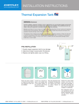
THERMAL EXPANSION
As water is heated, it expands (thermal expansion). In a closed
system the volume of water will grow when it is heated. As the
volume of water grows there will be a corresponding increase in
water pressure due to thermal expansion. Thermal expansion can
cause premature tank failure (leakage). This type of failure is not
covered under the limited warranty. Thermal expansion can also
cause intermittent temperature-pressure relief valve operation:
water discharged from the valve due to excessive pressure build
up. This condition is not covered under the limited warranty. The
temperature-pressure relief valve is not intended for the constant
relief of thermal expansion.
A properly sized thermal expansion tank must be installed on all
closed systems to control the harmful effects of thermal expansion.
Contact a local plumbing service agency to have a thermal expansion
tank installed.
TABLE 1. BRANCH CIRCUIT WIRE SIZE.
These ampacities relate only to conductors described
in Table 310-13 of the NEC. For ambient temperatures
over 30°C, see Correction Factors, Note 13 in the NEC.
GENERAL
Check the water heater model and rating plate information against
the characteristics of the branch circuit electrical supply. Do not
connect the heater to an improper source of electricity.
Voltage applied to the heater should not vary more than +5% to -10%
of the model and rating plate marking for satisfactory operation.
Do NOT energize the branch circuit for any reason before the water
heater tank is lled with water. Doing so may cause the heating
elements to fail.
The factory wiring is attached to a terminal block on the unit. The
branch circuit is connected to the block through an opening provided
on the heater. Factory terminal block has 500 MCM maximum
copper wire size capacity in each opening. If apparent eld wire
size is over 500 MCM multiple terminal blocks will be furnished.
If other opening sizes are desired they should be specied when
unit is ordered.
The installation must conform with these instructions and the
local code authority having jurisdiction and the requirements of
the power company. In the absence of local codes, the installation
must comply with the current editions of the National Electrical
Code, NFPA 70 or the Canadian Electrical Code CSA C22.1.
BRANCH CIRCUIT
The branch circuit wire size should be established through
reference to the NEC (National Electrical Code) or other locally
approved sources in conjunction with the water heater amperage
rating.. Wire rated at 75°C should be used. For convenience,
portions of the wire size tables from the Code are reproduced in
Table 1. It is suggested the electrician size the branch circuit at
125 percent of the heater rating and further increase wire size as
necessary to compensate for voltage drop in long runs. Voltage
drop should not exceed 3% at the water heater.
HEATER CIRCUITS
The water heater’s electrical components are pictured and identied
by the Features and Components illustrations on pages 9 and 10.
The model and rating plate illustration identies the heater electrical
characteristics. The heater has two electrical circuits:
Control Circuit: 120V circuit containing all safety and control devices.
The control circuit operates the contactors in the power circuit.
Power Circuit: High voltage, single or three phase circuit that carries
the heating element load.
The following section and pages describe the water heater circuits
and includes wiring diagrams.

ELECTRICAL AND RECOVERIES DATA
14
TABLE 2.
CONTROL CIRCUITS
The heater is equipped with one of the following control circuits,
resulting in:
A. Thermostats (mechanical)... where all of the heating elements
are switched on/off by one or more thermostats. Heaters
with thermostat control are adjusted as described in TEMPERATURE
REGULATION section of this manual, see Page 19.
B. Step controlled element operation...where elements are staged
on/off individually or in groups rotationally by the controller.
An optional feature is modulation which operates in conjunction with
the staged on/off element operation.
C. Sequencer... operates in conjunction with a thermostat (mechanical).
The sequence is activated by a thermostat then the sequence
switches on the heater elements in 3 sequences (multiple elements
and contactors are required).
Additional instructional literature is provided with heaters equipped
with modulating solid state step control or a sequencer.
All control circuits are operated on single-phase 120 volt current.
Control circuit wiring is 14 Awg, AWM (Appliance Wiring Material)
type, rated 600 volts, 105°C.
Standard equipment includes control circuit fusing.
POWER CIRCUIT
Power circuit wiring is type THHN (or equivalent) rated 600 volts,
105°C, sized as necessary.
The following wiring diagrams are included in this manual to show
typical arrangements of electrical components in the control and power
circuits by voltage and phase characteristics. They are to be used as
a reference by the installer or servicer in performing their work. An
actual diagram of the water heater wiring is furnished with the heater.

15
WIRING DIAGRAMSWIRING DIAGRAMS
DIAGRAM 2. LARGE COMMERCIAL WIRE DIAGRAM 300-600V/3PH W/O SLAVES
DIAGRAM 1. LARGE COMMERCIAL WIRE DIAGRAM 208-240V / 3PH W/O SLAVES

16
DIAGRAM3:LARGECOMMERCIALWIREDIAGRAM(WYE)300V-600V/3PHWITHSLAVES.

17
DIAGRAM 4. LARGE COMMERCIAL WIRE DIAGRAM (DELTA) 208V - 240V/3PH WITH SLAVES.

WIRING DIAGRAMSOPERATION
18
GENERAL
Refer to the Features and Components section of this manual
(pages 9 & 10) for the location of components mentioned in the
instructions that follow.
NEVER operate the heating elements without being certain
the water heater is filled with water, and a temperature and
pressure relief valve is installed in the relief valve opening on
top of the heater.
An electric type low water cutoff is provided on all heaters as
standard equipment. The water probe is installed near the top
of the tank to monitor the presence of water. The control circuit
is opened if the water level is below this point.
The pilot switch (power on/off toggle switch) on the cabinet front
permits the heater to be turned on and off without having to
operate the electrical disconnect switch.
Full power is present whenever the
cabinet door is opened even with
the pilot switch turned off.
DANGER
Optional manual override switches on the cabinet front allow
elements to be manually de-energized if full capacity is not needed.
FILLING THE WATER HEATER
Property Damage Hazard
In order to avoid water heater damage, fill tank with
water before operating.
CAUTION
To ll the water heater with water:
1. Turn off the electrical disconnect switch.
2. Turn off pilot toggle switch.
3. Close the heater drain valve.
4. Open a nearby hot water faucet to allow the air in the system to escape.
5. Fully open the cold water inlet valve, lling the heater and piping.
6. Close the hot water faucet when water starts to flow from the
faucet. Leave the cold water inlet valve fully open. The heater
is now ready for start up and temperature regulation.
7. Close the cabinet door and perform start up checks listed below
before turning on the electricity.
INITIAL START UP
The following checks should be made by the installer when the
water heater is placed into operation for the rst time:
1. Check all factory and eld made water and electrical connections
for tightness. Also check connections on top of the heater. Repair
water leaks and tighten electrical connections as necessary.
2. Turn on the electrical disconnect switch and pilot toggle switch.
The pilot toggle switch is located on cabinet.
3. Observe the operation of the electrical components during
the rst heating cycle. USE CARE AS THE ELECTRICAL
CIRCUITS ARE ENERGIZED.
Temperature control and contactor operation should be checked
by allowing heater to come up to temperature and shut off
automatically. USE CARE AS THE ELECTRICAL CIRCUITS
ARE ENERGIZED.
DRAINING THE WATER HEATER
The water heater must be drained if it is to be shut down and/
or exposed to freezing temperatures. Maintenance and service
procedures may also require draining the heater.
1. Turn off the electrical disconnect switch.
2. Turn off pilot toggle switch.
3. Close the cold water inlet valve to heater.
4. Open a nearby hot water faucet to vent the system.
5. Open drain valve.
6. If the heater is being drained for an extended shutdown, it is
suggested the drain valve be left open during this period.
Follow FILLING instructions when restoring hot water service, see
the list above.
• Burn hazard.
• Hot water discharge.
• Keep clear of drain valve
discharge outlet.
DANGER

19
HIGH TEMPERATURE LIMIT CONTROLS (ECO)
If a HWL L4008A series high limit is used in place of the ECO in
the probe it (HWL L4008A) should not be set above 190°F/88°C.
When the ECO switch contacts open (activate) the electronic
control system locks out and displays a Fault message. Voltage to
the contactor coils and heating elements is terminated to prevent
further heating operation. Should the ECO activate, the water
temperature must drop below 120°F/49°C before the control
system can be reset. Once the water temperature has cooled
below this point the power supply to the water heater must be
turned off and on again to reset the control system.
Water temperature over 125°F (52°C)
can cause severe burns instantly
resulting in severe injury or death.
Children, the elderly and the physically
or mentally disabled are at highest risk
for scald injury.
Feel water before bathing or showering.
Temperature limiting devices such as
mixing valves must be installed when
required by codes and to ensure safe
temperatures at fixtures.
Read instruction manual for safe
temperature setting.
DANGER
THERMOSTAT CONTROLS
The water heaters covered in this instruction manual are equipped
with adjustable thermostat controls to control water temperature.
Hot water temperatures required for automatic dishwasher and
laundry use can cause scald burns resulting in serious personal
injury and/or death. The temperature at which injury occurs varies
with the person’s age and duration of exposure. The slower
response time of children, the elderly or disabled persons increases
the hazards to them. Never allow small children to use a hot water
tap or draw their own bath water. Never leave a child or disabled
person unattended in a bathtub or shower. The water heater should
be located in an area where the general public does not have
access to set temperatures.
Setting the water heater temperatures at 120°F will reduce the risk of
scalds. Some States require settings at specic lower temperatures.
The following table shows the approximate time-to-burn relationship
for normal adult skin.
TEMPERATURE ADJUSTMENT
Full power is present whenever the
cabinet door is opened even with
the pilot switch turned off.
DANGER
The water heaters covered in this instruction manual are equipped
with an electronic control system. The control system senses
temperature from a factory installed immersion temperature probe
– see the Features and Components illustrations at the beginning
of this manual for location. The “Operating Set Point” is adjusted to
control water temperature. This is an adjustable user setting in the
control system’s “Temperatures Menu.” This and all control system
menus are accessed through the UIM (User Interface Module)
located on the front panel of the water heater. See Figure 1.
The Operating Set Point is adjustable from 90°F/42°C to 190°F/88°C.
The factory setting is 120°F/49°C. See the Control System Operation
section of this manual for instructions on how to adjust the Operating
Set Point and other user settings.
Set the Operating Set Point at the lowest setting which produces an
acceptable hot water supply. This will always give the most energy
efcient operation.
FIGURE 1. UIM (User Interface Module).
Water
Temperature °F
Time for 1st Degree Burn
(LessSevereBurns)
Time for Permanent Burns
2nd & 3rd Degree
(MostSevereBurns)
110 (normal shower temp.)
116 (pain threshold)
116 35 minutes 45 minutes
122 1 minute 5 minutes
131 5 seconds 25 seconds
140 2 seconds 5 seconds
149 1 second 2 seconds
154 instantaneous 1 second
(U.S. Government Memorandum, C.P.S.C., Peter L. Armstrong, Sept. 15,1978)
TEMPERATURE REGULATION

20
CONTROL SYSTEM OPERATION
HEATING ELEMENT OPERATION
ProgressiveSequencing: Elements are energized and de-energized
according to adjustable (1 to 20°F) Differential set points for each element.
Element Rotation - rst element on is rotated with each successive call
for heat. First On/First Off - the rst heating element energized at the
beginning of a heating cycle is the rst element de-energized at the
end of the heating cycle. Successive heating cycles would progress as
follows on a model equipped with 3 heating elements:
• First heating cycle: Elements come on [1, 2, 3] and cycle off [1, 2, 3].
• Second heating cycle: Elements come on [2, 3, 1] and cycle off [2, 3, 1].
• Third heating cycle: Elements come on: [3, 1, 2] and cycle off [3, 1, 2].
• Fourth heating cycle: pattern repeats - same as rst.
CONTROL SYSTEM FEATURES
AdvancedDiagnostics
Plain English text and animated icons display detailed operational
and diagnostic information. LCD screen on the front of the water
heater displays the Sequence of Operation in real time. Fault or
Alert messages are displayed when operational problems occur.
Advanced Service menu displays a list of possible causes for current
Fault and Alert conditions to aid in servicing.
EconomyModeOperation
Control system automatically lowers the Operating Set Point by a
programmed value during user dened time periods. Helps reduce
operating costs during unoccupied or peak demand periods.
CONTROL SYSTEM NAVIGATION
The UIM (User Interface Module) is located on the front cabinet of the water
heater. All operational information and user settings are displayed and
accessed using the UIM. The UIM includes ve snap acting (momentary)
user input buttons; an Up, Down and 3 Operational Buttons.
Up & Down Buttons
Used to navigate (up and down) and to select (highlight) menu items.
Also used to adjust or change (increase/decrease, on/off, set time)
various user settings.
Operational Buttons
The 3 Operational Buttons are multifunctional. Their current function
is dened by the text that appears directly above each button on
the LCD screen. The function will change depending on what menu
is currently displayed or what menu item is selected. When no text
appears on the LCD screen above an Operational Button there is no
function assigned.
THE DESKTOP SCREEN
The illustration below shows the control system “Desktop Screen.”
This is the default screen. If there are no active Fault or Alert
conditions and no user input for approximately 10 minutes the control
system will return to this screen automatically.
ModelInformation: Model information and menu titles are shown in
the black bar at the top of the Desktop Screen.
TankTemperature: Current water temperature as sensed from the
immersion Temperature Probe.
OperatingSetPoint: Temperature at which the control system will
maintain tank (water) temperature in the Normal Mode. This line of
text will read Economy Set Point whenever the control system is
operating in the Economy Mode.
Status: The Operating State of the control system is displayed
beneath the Operating Set Point.
Menu: The left Operational Button is pressed to enter the Main Menu
where all control system menus are accessed. See Table 3 on page
10 for a list of control system menus.
Help: The right Operational Button is pressed to access instructions
and explanations for user settings, Operating States, Status Icons,
manufacturer’s web address, technical support phone number and
service agent contact information.
Day/Time/Operating Mode: The current time and day are also
displayed on the Desktop Screen. “Clock Not Set” will be displayed
until the time clock has been initially set. Day and Time are adjusted
in the Economy Mode Setup menu. The current Operating Mode,
either Normal Mode or Economy Mode, is displayed beneath the
day and time.
Discreet Menu Contact Information: From the Desktop Screen
press and hold down the middle (unmarked) Operational Button for
30 seconds and then release it. This will launch a discreet menu
where personalized contact information can be entered. Installing
contractors and/or service agents can enter their company name
and telephone number. This contact information will be displayed
with all Fault and Alert messages.
/