Page is loading ...

Copyright © 2016 Maretron, LLP All Rights Reserved P/N: M003017 Rev. 1.3 3/16
Installation Instructions
10271 1-1/2" FPT Cooling Water Flow Switch
Introduction
The Maretron 10271 is an accessory for the SIM100 Switch Indicator Module. The 10271 has a set of normally
closed contacts that will open whenever a flow of cooling water of a user-settable amount is detected.
Instructions
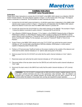
Please follow these instructions to connect the 10271 to the NMEA 2000 network via a Maretron SIM100 Switch
Indicator Module. The wiring diagram appears in Figure 1. The diagram shows a connection to channel #1, but
connections to other channels are similar. Please refer to the original manufacturer’s instructions packaged with
the product for additional details including setting of the switch activation flow rate.
1. Install the two wires from the 10271 to a free switch channel on the SIM100. The two wires are
interchangeable. The example in Figure 1 shows the flow switch connected to switch channel 1, terminals
SW1A and SW1B.
2. Use a Maretron DSM150 or DSM250 display or Maretron N2KAnalyzer software to set the switch channel
mode (indicated as “Channel #x Mode” on the DSM250) for the appropriate channel to the “No End of
Line Resistor” setting. For this example, you would set “Channel #1 Mode” to “No End of Line Resistor”.
3. Supply Power to the NMEA 2000 network, Verify that the switch channel indicates an “on” (normal) state
using Maretron N2KView software, N2KAnalyzer, or other product capable of displaying switch indicator
state.
4. Start cooling water flow through the 10271 and verify that the switch channel indicates an “off” state.
1
2
5
4
3
6
7
8
9
10
11
12
SW1A
SW2B
SIM100 Screw Terminals
SW1B
SW2A
SW3A
SW3B
SW4A
SW4B
SW5A
SW5B
SW6A
SW6B
Flow
Switch
Figure 1 - Wiring Diagram

Copyright © 2016 Maretron, LLP All Rights Reserved P/N: M003017 Rev. 1.3 3/16
Device Specifications
Parameter
Value
Inside Diameter
1.5” (38.1mm)
Outside Diameter
2.25” (57.2mm)
Length
4.36” (110.7mm)
Height
6.69” (169.9mm)
Activation Flow Rate
6 – 8 GPM (22.7 – 30.3 LPM)
Contacts
Normally Closed
Connections
1-1/2” FPT Female
Switching Rating
50W
Switching Voltage (Max)
300VAC / 300VDC
Maximum Switching
3.0A
Heat Resistance, Continuous
210°F (99°C)
Maximum Pressure
120 PSI @ 72°F
8.3 bar @ 22°C
External Fasteners
18-8 Stainless Steel
Construction
CPVC Schedule 80
Connection
5’ (1.5m) Marine Grade Tinned Wire Leads
Gasket
EPDM
For installation support, please contact:
Maretron, LLP
9014 N. 23
rd
Ave #10
Phoenix, AZ 85021-7850
Telephone: (+1) 866-550-9100
E-mail: [email protected]
Web: http://www.maretron.com
/