Page is loading ...

Copyright © 2011 Maretron, LLP All Rights Reserved P/N: M001803 Rev.1.2 1/11
Installation Instructions
MD-6517-N Motion Detector
Instructions
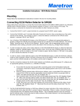
Please follow these instructions to connect the MD-6517-N to the NMEA 2000 network via a Maretron SIM100
Switch Indicator Module. The wiring diagram appears in Figure 1 on the reverse of this page. The diagram shows
a connection to channel #1, but connections to other channels are similar.
1. Connect the MD-6517-N power terminals to a 7-16VDC supply that is independent of the NMEA 2000
network power supply as shown in Figure 1 below. Powering the unit separately from the NMEA 2000
network allows the detector to work even when the NMEA 2000 network is powered off.
2. Connect the COM and T/NO terminals to a free switch channel. The example in Figure 1 shows the
detector connected to switch channel 1, terminals “SW1A” and “SW1B”.
3. Use a Maretron DSM250 display (firmware 1.3.5 or higher), the DSM250 Viewing function of Maretron
N2KAnalyzer software, or other Maretron display product capable of configuring the SIM100 to set the
switch channel mode (indicated as “Channel #x Mode” on the DSM250) for the appropriate channel to the
“End of Line Resistor” setting. For this example, you would set “Channel #1 Mode” to “End of Line
Resistor”.
4. Supply power to the NMEA 2000 network and to the MD-6517-N and verify that the switch channel
indicates an “off” (normal) state using Maretron N2KView software, N2KAnalyzer, or other product
capable of displaying switch indicator state.
5. Perform a walktest on the MD-6517-N and verify that the switch channel indicates an “on” (alarm) state
during the test.
6. Disconnect one of the alarm wires from the SIM100 and verify that the switch channel indicates an “error”
state.
7. Reconnect the alarm wires to the SIM100 and verify that the switch channel indicates an “off” (normal)
state.
WARNING: The MD-6517-N is shipped with an 8KΩ end-of-line resistor installed between the
COM terminal and the T/NO terminal. Do not remove the resistor, as it is required for proper
operation.
(continued on reverse)

Copyright © 2011 Maretron, LLP All Rights Reserved P/N: M001803 Rev.1.2 1/11
For installation support, please contact:
Maretron, LLP
9014 N. 23
rd
Ave #10
Phoenix, AZ 85021
Telephone: (+1) 866-550-9100
E-mail: [email protected]
Web: http://www.maretron.com
1
2
5
4
3
6
7
8
9
10
11
12
SW1A
SW2B
SIM100 Screw Terminals
SW1B
SW2A
SW3A
SW3B
SW4A
SW4B
SW5A
SW5B
SW6A
SW6B
+
-
7-16VDC
MD-6517-N
NC COM T/NO TAMP + -
Factory-installed
8 KΩ end-of- line
resistor
Figure 1 – Wiring Diagram
/