Page is loading ...

CONFOCAL APPLICATION LETTER
reSOLUTION
No.45, June 2014
Triggering with Leica TCS SP8 and DM6000 CFS –
an Application Guide

2
Contents
1 Introduction 3
2 The Leica Trigger Unit 4
2.1 Trigger Unit – Pins on the front 4
2.2 Trigger Unit – Pins on the back 5
3 Trigger timing 6
3.1 Timing for trigger in 6
3.2 Timing for Trigger out 6
4 Rising or Falling Edge of the Trigger Pulse 7
5 How to Configure Triggers in the LAS AF Software? 8
6 Input Triggers 9
6.1 Wiring diagram for input triggering 9
6.2 Range of function for applications with input triggering 10
6.2.1 Trigger in at the beginning of a time lapse experiment 10
6.2.2 Delayed input trigger 11
6.2.3 Delayed and repeated input triggers 12
6.2.4 Triggering of each frame 13
7 Output Triggers 14
7.1 Wiring diagram Trigger OUT 15
7.2 Range of function for applications with output triggering 16
7.2.1 Trigger out at the beginning or end of a time lapse experiment 16
7.2.2 Delayed output trigger for xyt-series 17
7.2.3 Delayed and repeated output trigger pulses for xyt-series 18
7.2.4 Delayed and repeated output trigger pulses for xt-series and xyt-series 19
8 Appendix 21
I Functional range of the trigger unit 21
II Connectors and explanations 22
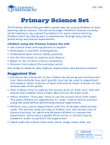
Titel page:
Queen Triggerfish (Balistes vetula).
Image: Courtesy of http://www.inthetank.co.uk/fish-2/triggerfish/queen-triggerfish (image modified by Leica Microsystems).
http://www.youtube.com/watch?v=rKO_wMsLEek
Trigger fish have an unusual defence mechanism; A strong dorsal spine which can be locked in place by a smaller spine.
When approached by a predator it can dart into a small opening and ‘trigger’ this mechanism thus locking itself inside the opening.
Most are solitary, and they have strong teeth which allow them to feast on most things including molluscs and sea urchins. They
can swim horizontally or diagonally and are aggressively protective of their eggs, which are laid in large circular nests in the sand.
http://animals.nationalgeographic.com/animals/fish/triggerfish/#
The Balistidae family takes its common name from a set of spines the fish use to deter predators or to “lock” themselves into holes,
crevices, and other hiding spots. The system can be “unlocked” by depressing a smaller, “trigger” spine.

3RESOLUTION – TRIGGERING WITH LEICA TCS SP8 AND DM6000 CFS
1 Introduction
Communication between instruments is crucial in physio-
logical experiments to coordinate image acquisition and
physiological measurements. A common method for syn-
chronizing imaging and electrophysiological measurement
devices is the use of trigger signals.
Triggering devices provide voltage signals used to generate
a notification to external devices. The trigger signal can
represent by the rising or falling edge of a voltage change,
i.e., a pulse, the logic combination of two signals, or a cer-
tain level that will release a trigger signal when it falls
below or exceeds. In an experimental setup, there is always
a reference system. The trigger signals are named accord-
ing to the reference system, which is in our case the Leica
TCS SP8.
All trigger signals that leave the reference system are
called trigger out signals or output triggers. Trigger sig-
nals coming from a different instrument and going into the
reference system are called trigger in signals or input
triggers (Figure 1). In most cases trigger in and trigger out
signals are very short voltage changes going from 0 to 5V.
A trigger signal is also referred to as a Transistor-Transistor
Logic (TTL) pulse.
This document provides detailed information about trigger-
ing with the Leica TCS SP8 or DM6000 CFS-system.
Examples of TCS SP8 triggering situations include transfer-
ring line and frame start information of the TCS SP8 to
counting electronics (FLIM), and synchronization of optical
imaging and electrophysiological measurements (Figure 2).
Trigger out
Patch clamp setup,
stimulation
electrode
Imaging system
TCS SP8,
DM6000 CFS
Trigger in
Figure 1: Communication between instruments by triggering: The Leica TCS SP8
is the „reference system“: Trigger signals leaving the TCS SP8 are called Trigger
out signals; trigger signals going into the TCS SP8 are called trigger in signals.
Figure 2: Detail of Figure 2 showing the objective lens for optical imaging, the
mini-chamber for keeping the brain slice under physiological conditions, and
the stimulation electrode at the blue holder.
Courtesy: Dr. Thomas Nevian, Inst. of Physiology, Univ of Bern, Switzerland

4
2 The Leica Trigger Unit
For triggering with the TCS SP8 DM6000 CFS a device is needed that acts as a physical interface between the SP8 scan
head and the external instrument(s). This device, called Leica trigger unit, is a mandatory piece of equipment for triggering
applications. It can be operated with and without an external power supply. This depends on the voltage range required
for output triggering (details see below). For all triggering applications the trigger unit has to be connected to the scanhead
of the SP8-system.
The following section describes the functional range of all connectors on the trigger unit.
2.1 Trigger Unit – Pins on the front
Figure 3: Front of trigger unit
1
Sync In 50 Ohm:
“Sync In 1 and 2” can be used for the synchronization of
the TCS SP8-scanner with pulsed lasers such as the MP
lasers (80MHz pulse repetition rate) used for FLIM, STED.
Pulses of the “Sync In” go to the scan electronics.
2
Trigger In 1 and 2 (Plugs for input triggers to be
connected with external device):
With these two pins the trigger unit can receive input
trigger signals (Trigger In) of 0 V to 5 V (TTL) – the sig-
nals are transferred to the scan head to start scanning.
The signal needs 1µsec transfer time from the trigger
unit to the scan head.
Maximum input voltage for trigger in is 5,5 V – no
matter if the external power supply is used or not.
The use of higher voltages will damage the trig-
ger unit! Usually used: 5 V.
These triggers can be freely configured within the LAS
AF software tools Live Data Mode and tool Electrophys-
iology. The triggers are configured within the Trigger
Settings window in LAS AF (see section 6, page 11).
The Trigger In 1 and 2 operate in xyt-scan as well as in
xt-scan mode. Upon activation of the xt-scan mode,
the xt-dialog shows pages. For the definition of triggers,
pages are handled equivalent to frames.
Example: if a page is composed of 400 lines and a trig-
ger in is set to repeat every single frame, the system
scans 400 lines (= 1 page) when 1 trigger arrives.
3
Trigger Out – Common characteristics of trigger
out signals 1–8:
The signals are generated in the scan head. The refresh
rate of these ports is 1 MHz. The signal needs 1µsec
transfer time from the scan head to the external instru-
ment. The ports are electrically isolated from the scanner.
Voltage range for trigger out:
The IO/standard is LVTTL (0V…3.3 V) without ex-
ternal power supply, and TTL (0 V…5 V) when an
external power supply for the trigger unit is used.
Trigger Out 1–4 (Plugs for output triggers to be con-
nected with external devices): are freely configurable in
the LAS AF software tools Live Data Mode and Electro-
physiology. The triggers are configured within the Trig-
ger Settings window (See section 7, page18).
Trigger Out 5–8
These standard trigger out signals are created indepen-
dent from any application. They are automatically cre-
ated in the scan head.
Trigger Out 5
This signal is sent out from the scan head whenever the
scanner is active; it is automatically generated.
For the DM6000 CFS (electrophysiology-system) it is
used as a the sample clock for the National Instruments
Data Acquisition box. In this case it needs to be con-
nected to plug “CTR 0 OUT” on the NI-Data Acquisition
box.
1 2 3 4

5RESOLUTION – TRIGGERING WITH LEICA TCS SP8 AND DM6000 CFS
Trigger Out 8
This signal is an automatically generated out trigger; a
frame trigger needed for the ROI-spectrometer.
It is used with DM6000 CFS to trigger the data acquisi-
tion start. Therefore, it needs to be connected to plug
“AI START” on the National Instruments Data Acquisi-
tion box.
4
Sync Out 1, Sync Out 2
Sampling/Refresh rate is 40MHz,
Sync Out 2 is the pixel clock – the clock generator for
scanning.
Figure 4: Rear side of trigger unit
8
Connector Scan Head/trigger unit:
This pin is used to connect the scan head to the trigger
unit. The trigger unit needs to be connected to the scan
head to pass trigger signals to the trigger unit and vice
versa. In addition, the trigger unit gets 3.3 V power from
the scan head. The trigger unit can be used with and
without an external power supply.
5 6 7 8
Trigger Out 6 and 7
are automatically created in the scan head: frame trig-
ger (Trigger Out 6), line trigger (Trigger Out 7).
These standard trigger out signals are created indepen-
dently from any application.
They can be used to monitor the scanning process in the
LAS AF software via the Data Acquisition (DAQ) box, by
an oscilloscope, or by external instruments and soft-
ware, e.g., Axon Instruments. For electrophysiological
applications they can be used to visualize the line- and
frame-scanning in combination with recorded voltage
data, etc.
2.2 Trigger Unit – Pins on the back
5
Optional Trigger I/0:
Provides several additional signals via a D-SUB pin.
Maximum input voltage 3.3 V.
Higher voltages will damage the trigger unit!
With external power supply the maximum input voltage
is also 3.3 V.
Sampling/Refresh rate is 1 µsec;
4 additional inputs (Trigger In) can be configured within
the LAS AF Trigger Settings window.
The user has to build up an own adapter to get access
to these triggers.
6
Trigger Out – Sync Out NIM and Synch out 50 Ohm:
Very fast output triggers (40 MHz).
7
Opt DC In:
It is the connector (see arrow) for an external power
supply and for optional use. It enables the user to get a
5V trigger signal out.
Without an external power supply the trigger unit can
receive triggers of max. 3.3 V (Trigger In 1 and 2). It can
send out triggers (Triggers Out 1–8) of max 3.3 V.
Using an external power supply the trigger unit can
receive triggers of max. 5 V (Trigger in 1 and 2). It can
send out triggers (Triggers out 1–8) of max 5 V.
Note: The indication “12 V” refers to the scan head trig-
ger unit connection described below in
8
.

6
3 Trigger timing
3.1 Timing for trigger in
The scan starts after an incoming trigger is associated with
the movement of the scanning mirrors. The image acquisi-
tion starts when the scanning mirrors have reached their
proper positions for scanning. Figure 5 shows the relationship
between an arriving input trigger and the start of the scan.
The needed time duration (ΔT) from the arrival of a trigger
pulse at the Leica TCS SP8 to the scan of the 1st image
pixel is constant for a given scan format. It depends on the
scan speed and on the scanning mode (uni- or bi-directional).
Therefore, the ΔT can be very precisely predicted (Figure 6).
Image
Time
Trigger
Δ
T
Figure 5: ΔT is the needed time duration from the beginning
of a trigger pulse to the scan start.
Figure 6: Table of ΔT for input triggers on Leica TCS SP8 systems. Data in ms.
3.2 Timing for Trigger out
The different types of available output trigger signals have different timing characteristics:
1. Trigger out on frames (free configurable by the user for
xy- and xt-scanning mode via the LAS AF user interface)
and line and frame trigger out (automatically generated):
These triggers have no delay since they are exactly syn-
chronized with the position of the x-scan mirror.
2. Trigger out on function start/end:
These triggers are software-controlled and cannot be
predicted as the input triggers.
ΔT for input triggers on Leica TCS SP8 systems (ms)
Scan Speed (Hz)
unindirectional (bidir)
16 32 64 128 256 512 1024 2048 4096 8192
100
(200)
320
(160)
620
(310)
100
(50)
100
(50)
100
(50)
100
(50)
100
(50)
200
(400)
160
(80)
310
(155)
50
(25)
50
(25)
50
(25)
50
(50)
50
(50)
400
(800)
80
(40)
155
(77.5)
25
(15)
25
(17.5)
25
(15)
25
(15)
25
(15)
25
(15)
25
(15)
40
(15)
700
(1400)
45
(22.8)
88.5
(44.2)
17.1
(15.7)
17.1
(15.7)
17.1
(15.7)
17
(15)
17
(15)
1000
(2000)
32
(16)
62
(31)
16
(16)
16
(15)
16
(15)
16
(15)
16
(15)
16
(15)
1400
(2800)
22.8
(11.4)
44.3
(22.1)
15.7
(15)
15.7
(15)
11.4
(15)
17
(15.7)
17
(15.7)
17
(15.7)
Resonant Scanner 8000
(16000)
4
(2)
7.7
(3.87)
2
(1.65)
2.5
(1.87)
3.75
(2.37)
5.75
(3.5)
10.25
(5.62)
In addition to the ΔT, a short period of time is required to
position the second scanning mirror (x). This time duration
cannot be predicted and is therefore a jitter. The maximum
jitter time that is required is equal to the time needed to
scan one line (for 1000 Hz = 1 ms).
However, input triggers react very fast and are reproduc-
ible. Without considering the little jitter, the reproducibility
is within 10 µs.

7RESOLUTION – TRIGGERING WITH LEICA TCS SP8 AND DM6000 CFS
Figure 7: Trigger settings in LAS AF to define the control for triggering by a rising or falling edge of trigger
pulses. A list is displayed with all free configurable triggers. The edge of the pulse is referred to as the Pulse
Form: low = falling edge, high = rising edge.
Please note: IN 3–IN 6 provides 4 additional inputs that require building up an adapter to get access to these
triggers.
4 Trigger Pulse Edges
Triggering with the Leica TCS SP8 is controlled by the “edges”
of the trigger pulses – falling or rising edges. The hardware
that should be triggered must recognize the voltage change
from high to low and vice versa.
By default, the Leica TCS SP8 uses a falling edge for the
trigger in signals. The time delay (ΔT) between the arrival
of an external trigger in signal and the scan start can be
demonstrated when frame or line triggers are simultane-
ously recorded. These trigger signals are automatically cre-
ated by the TCS SP8 and can be visualized to monitor the
scanning process.
The control for triggering by a rising or falling edge of trig-
ger pulses can be defined in the LAS AF software. In Con-
figurations, a click on EP/Trig opens a window for Trigger
Settings (Figure 7). Here, a list is displayed with all freely
configurable triggers. The edge of the pulse is referred to
as the Pulse Form:
low = falling edge,
high = rising edge.
The default trigger setting is at Low (falling edge) for all
triggers. Just click on High to select for rising edge.

8
5 How to Configure Triggers
in the LAS AF Software?
This section describes the different trigger capabilities,
that can performed with the Leica TCS SP8 or DM6000 CFS.
There are three prerequisites for triggering applications:
1. The system must be equipped with the Leica trigger
unit;
2. Trigger cables need to be present;
3. The software license for the Electrophysiology tool or
for the Live Data Mode must be active. Within one of
these tools, triggers can be assigned.
After the definition of one or several Jobs within Electro-
physiology or Live Data Mode, a Job must be selected to
which a trigger should be assigned. By a click on that Job
and a subsequent right mouse click a list of options opens
(Figure 8). By selecting Trigger the Trigger Settings win-
dow (Figure 9) opens.
The Trigger Settings window (Figure 9) allows input
(Trigger In) and output triggers (Trigger Out). Different
options are available, including triggering within xt-scans.
A defined trigger is automatically assigned to the selected
Job.
Figure 8: Options for Job handling.

9RESOLUTION – TRIGGERING WITH LEICA TCS SP8 AND DM6000 CFS
A signal from an external device is
used to trigger the start of the data
acquisition with the Leica TCS SP8.
This approach is required to synchro-
nize data acquisition and stimulation
of neurons by a microelectrode. With
the Leica LAS AF software two input
triggers can be freely configured for
these applications – trigger IN 1 and
trigger IN 2.
To assign an input trigger to a job, the
appropriate trigger channel has to be
selected from the drop down list with-
in the Trigger Settings window
(arrow in Figure), e.g., IN 1.
Figure 11: Trigger In: The scan start of the Leica TCS SP8 is
triggered by an incoming trigger signal from a patch clamp
amplifier (DA output signal). The analog output of the
patch clamp amplifier is connected to the Trigger In 1 plug
of the trigger unit.
Figure 9: Triggers Settings window.
The area for definition of input triggers is
bordered. Details are described below.
6 Input Triggers
By using the two trigger in pins the trigger unit can receive
input trigger signals of 0V to 5 V (TTL) from an external
device. The signals from the external instrument are then
transferred to the scanhead to synchronize the scan start.
Usually, scanning is triggered through an output signal of
an external device. Thus, the D/A-output of the external
instrument needs to be connected to the Trigger In pin
(Trigger In 1 or Trigger In 2) of the trigger unit (see Figure 11).
6.1 Wiring diagram for input triggering
SP8 Scanhead
Trigger Unit
External Device
D/A Output
digital signal
Trigger In
Wiring diagram Trigger IN
12
SP8 Scanhead
Trigger Unit
External Device
A/D Input
digital signal
Trigger Out
Wiring diagram Trigger OUT
1234
SP8 Scanhead
Trigger Unit
External Device
A/D Input
digital signal
Trigger Out
Wiring diagram Trigger OUT
1234
SP8 Scanhead
Trigger Unit
External Device
D/A Output
digital signal
Trigger In
Wiring diagram Trigger IN
12
Figure 10: Wiring for input triggering

10
This section gives an overview on the different options for
input triggering. A schematic of the experimental design, a
description of the Trigger Settings window in LAS AF, the
resulting user interface, and the quantification chart after
execution of the experiment are described.
6.2.1 Trigger in at the beginning
of a time lapse experiment
This option is valid for all experiments in physiology that
need to synchronize the scan start with the action of an
6.2 Range of function for applications
with input triggering
external instrument. For example, a TTL signal from a patch
clamp system is sent for triggering the scan start at the
beginning of a time lapse experiment (Figure 12 A). Here
the option Trigger IN on Frames has to be set in the LAS
AF Trigger Settings window (Figure 12 B). Then the trig-
ger iss displayed in the software interface (Figure 12 C). This
trigger option works in the xyt and yt scanning modes. The
resulting quantification chart shows that the scanning
starts after the arrival of the input trigger (Figure 12 D,
arrow).
Begin
External device
Trigger in
Scanner
Job
xyt-frames
End
Figure 12: Trigger in at beginning of a time lapse experiment (Job):
A
Schematic of experimental design for an input trigger received at the beginning of a Job to start the scanning process.
B
Settings in the Trigger Settings window of LAS AF for the experiment described in A; Selection of the trigger option Trigger IN
on Frames and trigger IN 1 from the list.
C
Indication of the trigger IN 1 at the start of the assigned Job in the time line of the Electrophysiology or Live Data Mode tool of LAS AF.
D
Chart after execution of a time lapse containing 10 frames. Blue: Trigger signal from a pulse generator, Green: Frame triggers
(Trigger Out 6) are recorded to monitor the scanning process.
A B C
D
Trigger pulse of external device

11RESOLUTION – TRIGGERING WITH LEICA TCS SP8 AND DM6000 CFS
6.2.2 Delayed input trigger
When cells or neuron dendrites have to be observed with-
out any stimulation for some time before a stimulation
pulse was sent, a delayed input trigger can be defined. This
trigger option works in the xyt and xt scanning modes. The
arrival of the input trigger, e.g., from a stimulation elec-
trode, has to be defined in First Trigger at … frame in the
field Trigger IN on Frames in the Trigger Settings win-
dow (Figure 13 B).
Begin
External device
Trigger out
Scanner
Job
xyt-frames
End
Figure 13: Delayed input trigger for continuing the scanning process:
A
Schematic of experimental design for an input trigger after a delay of 2 frames.
B
Settings in the Trigger Settings window of LAS AF for the experiment described; Selection of trigger IN 1 from the list in the field
Trigger IN on Frames using the option First Trigger at … frame for the delayed triggering.
C
Indication of the trigger IN 1 at the start of the assigned Job in the time line of the Electrophysiology or Live Data Mode tool of LAS AF.
Delay is not indicated.
D
Chart after execution of the time lapse containing 10 frames. Blue: D: Chart after execution of the experiment. Blue: Trigger signal from
a pulse generator, Green: Frame triggers (Trigger Out 6) are recorded to monitor the scanning process. Note that scanning is continued
after the 3rd frame upon the arrival of the trigger pulse.
A B C
D
Trigger pulse of external device

12
6.2.3 Delayed and repeated input triggers
The scanning process can be triggered upon the arrival of
repeated trigger signals at the Leica TCS SP8. Thus, scan-
ning is performed for a defined number of frames only
when a trigger signal arrives. This trigger option works in
xyt and xt scanning modes. The arrival of the first input trig-
ger has to be defined in First Trigger at … frames in the
field Trigger IN on Frames in the Trigger Settings win-
dow (Figure 14 B). In addition, the repetition frequency has
to be set in Repeat every … frames.
Begin
External device
Trigger in
Scanner
Job
xyt-frames
End
Figure 14: Delayed and repeated input triggering:
A
Schematic of experimental design for several input triggers after a delay.
B
Settings in the Trigger Settings window of LAS AF for the experiment described. Selection of trigger IN 1 from the list in the field
Trigger IN on Frames using the option First Trigger at … frame for the delayed triggering, and Repeat every … frames.
C
Indication of the trigger IN 1 at the start of the assigned Job in the time line of the Electrophysiology or Live Data Mode tool of LAS AF.
Delay is not indicated.
D
Chart after execution of the time lapse containing 10 frames. Blue: D: Chart after execution of the experiment. Blue: Trigger signal from
a pulse generator, Green: Frame triggers (Trigger Out 6) are recorded to monitor the scanning process. Note that scanning is continued
after the 3rd frame upon the arrival of the trigger pulse.
A B C
D
Trigger pulse of external device

13RESOLUTION – TRIGGERING WITH LEICA TCS SP8 AND DM6000 CFS
6.2.4 Triggering of each frame
Applications, such as the synchronization of the scanning
process with the heartbeat of a mouse, require fast scan-
ning and that every frame to be scanned is triggered by an
incoming trigger signal from an electro-cardio-graph. The
arrival of the first input trigger has to be defined in First
Trigger at … frame in the field Trigger IN on Frames in
the Trigger Settings window (Figure 15 A). This repetition
has to be set to 1 in Repeat every … frames.
Begin
External device
Trigger in
Scanner
Job
xyt-frames
End
Figure 15: An incoming signal triggers the scanning of each single frame:
A
Scheme of the experiment with triggering of each frame.
B
Description of experiment settings in the Trigger Settings window of LAS AF. Selection of trigger IN 1 from the list in the field
Trigger IN on Frame susing the option First trigger at 1 frame and Repeat every 1 frame for triggering of each single frame.
C
Indication of the trigger IN 1 at the start of the assigned Job in the time line of the Electrophysiology or Live Data Mode tool of LAS AF.
Delay is not indicated.
D
Chart after execution of the time lapse containing 10 frames. Blue: D: Chart after execution of the experiment. Blue: Trigger signal from
a pulse generator, Green: Frame triggers (Trigger Out 6) are recorded to monitor the scanning process. Note that scanning is continued
after the 3rd frame upon the arrival of the trigger pulse.
A B C
D

14
7 Output Triggers
Output triggers are trigger signals that are sent from the
Leica TCS SP8 to an external instrument to trigger the ac-
tion of that external instrument. The trigger signal is sent
from the scan head to the external device, e.g., a patch
clamp system, to start its operation. With the Leica LAS AF
software, four Output triggers can be freely configured.
To assign an output trigger to a job, the appropriate trigger
channel has to be selected from the drop down list within
the Trigger Settings window (see arrows in Figure 16).
Four output triggers can be freely configured to start the
action of an external device at a defined time point. The
software allows assigning a trigger to a certain part of the
experiment (Job).
Output triggers can be defined at the beginning and the end
of a job or a pause of the experiment and also at a certain
delay after the beginning of an experiment. Furthermore, it
is possible to send out trigger pulses that start at an arbi-
trary line within a frame (for xt-scans).
Figure 16: Options for Output Triggers are highlighted.

15RESOLUTION – TRIGGERING WITH LEICA TCS SP8 AND DM6000 CFS
The scanning process and the action of an external device
can be synchronized by using output trigger signals from
the SP8. The output trigger signals are transferred to the
external device via the Leica trigger unit (plugs Trigger out
1, 2, 3 or 4). Therfore, the SP8-scanhead is connected to the
trigger unit. Furthermore, the Trigger out plug of the trigger
unit needs to be connected with the A/D input of the exter-
nal device.
7.1 Wiring diagram Trigger OUT
Figure 17: Wiring for input triggering
SP8 Scanhead
Trigger Unit
External Device
A/D Input
digital signal
Trigger Out
1234

16
The following gives an overview on the different appli-
cation options for output triggering: A schematic of the
experimental design, a description of the Trigger Settings
window in LAS AF, the resulting user interface, and the
quantification chart after execution of the experiment are
described.
7.2 Range of function for applications
with output triggering
Begin
External device
Trigger out
Scanner
Job/Pause
xyt-frames
End
Begin
External device
Trigger
out
Scanner
Job/Pause
xyt-frames
End
Figure 18: Trigger out at the beginning or end of a timelapse:
A
and
B
Schematic of experimental design for an output trigger send at the beginning of a job (A) or at the end of a job (B) to start
the action of an external device.
C
Settings in the Trigger Settings window of LAS AF for the experiment described in A; Selection of triggers in the field Trigger OUT on
Function Start/End.
D
Indication of output triggers (here OUT 2) at the end of the assigned job in the time line in LAS AF.
E
Chart after excution of the timelapse containing 10 frames (Job1) and a second one containing 5 frames (Job 2). Blue: Trigger signal
from a pulse generator, green: Frame trigger recorded for monitoring the scanning process.
Note: These outputs are software controlled and are not exactly synchronized.
A B
E
Frames of Job 1 Frames of Job 2Trigger out
7.2.1 Trigger out at the beginning or end of a time
lapse experiment
For experiments that require an output trigger sent at the
beginning or at the end of the data acquisition, the trigger
option Trigger OUT on Function Start/End can be used.
Figure 18 shows the design, LAS AF user interface, and
result of such an experiment.
C
D

17RESOLUTION – TRIGGERING WITH LEICA TCS SP8 AND DM6000 CFS
Delay: 3 frames Trigger out
7.2.2 Delayed output trigger for xyt-series
In electrophysiology experiments can require sending out a
trigger pulse at a defined time point after starting the scan-
ning process, e.g., for experiments with delayed electrical
stimulation after a defined time of recording the steady
state of the non-stimulated cell. For this type of experiment
the trigger option Trigger OUT on Frames has to be used
(Figure 19).
Begin
External device
Trigger out
Scanner
Job
xyt-frames
End
Figure 19: Delayed output trigger:
A
Schematic of experimental design: A trigger is sent out after frame 3 of 10 frames (xyt-series).
B
Settings in the Trigger Settings window of LAS AF for the experiment described in A. Selection of the trigger in the field Trigger OUT
on Frames using the option First trigger at frame 4.
C
Indication of the trigger OUT 1 in the LAS AF user interface in Acquire according to the defined trigger as described in B.
D
Chart after execution of the experiment. Blue: trigger out signal at the beginning of frame 4, green: frame triggers recorded for
monitoring the scanning process.
Note: The trigger pulse is exactly synchronized with the scanning and has no delay.
A
B
C
D

18
Repeated Trigger out
7.2.3 Delayed and repeated output trigger pulses
for xyt-series
For experiments that require repeated actions of an exter-
nal instrument or several external instruments, such as
repeated electrical stimulations of a neuron, trigger pulses
need to be sent out from the SP8 to synchronize the
external device with a certain scheme of data acquisition.
Such trigger schemes can be easily configured. In addition,
repeated output triggers can also be delayed for monitoring
the steady state of cells without manipulation. Thus, out-
put triggers are sent starting at a certain frame and repeat-
ing at every x number of frames.
Begin
External device
Trigger out
Scanner
Job
xyt-frames
End
Figure 20: Delayed and repeated output trigger pulses:
A
Repeated output triggers are sent starting at a certain frame and repeating for experiments that require repeated actions of and
external instruments.
B
Trigger setting in LAS AF for experiment described in A. Selection of the trigger in the field Trigger OUT on Frames. The first trigger is set
to the 3rd frame. Every 4th frame a trigger pulse is sent out.
C
Chart after execution of a timelapse of 22 frames. Blue: Trigger signals, green: Frame triggers recorded for monitoring the scan process.
Note: Trigger pulses are exactly synchronized with the scanning and have no delay.
A
B
C

19RESOLUTION – TRIGGERING WITH LEICA TCS SP8 AND DM6000 CFS
7.2.4 Delayed and repeated output trigger pulses
for xt-series and xyt-series
In order to follow very fast reactions, e.g., calcium waves
and sparks in heart muscle cells, the fastest acquisition
mode xt line scan is required. For this scanning mode out-
put triggering can also be used to synchronize scanning and
measurement of electrical data.
For output triggers in xt-experiments and xyt-experiments
the duration (pulse width) of a trigger pulse can be adjust-
ed. This might be crucial for the proper communication of
external devices with the scanner. The pulse duration can
be defined by editing a number in Pulse Width (Dura-
tion). The delay of the trigger pulse from scan start can be
defined by entering a number in Delay lines from start by
(Figure 21). Figure 22 explains how the pulse width is
defined by the number of lines. In Figure 23 the graph of
such an experiment is displayed.
Figure 21: Trigger setting in LAS AF for an xt-experiment: xt-scan mode is activated
1
and 300 lines in one page are set
2
.
In the field Trigger OUT on Frames 100 lines delay from start and 20 lines duration of the trigger pulse
3
is defined.
1
2
3

20
Trigger Pulse Duration
4 lines delay
4 lines duration
of trigger pulse
t
lines
1
2
3
4
5
6
7
8
9
10
11
12
13
14
15
16
frame
Figure 22: Setting trigger pulse duration and delay time by defining lines:
Each line of a frame needs a defined time to be scanned. Thus, the duration of the trigger pulse can be set via
definition of the number of lines. Furthermore, a delay time from the scan start can be set by defining a number
of delay lines from frame start.
Figure 23: Graph of an xt-experiment with triggering (Trigger OUT on Frames):
The experiment was defined for duration of 300 lines, that are recorded as 1 frame by using the frame trigger
(Green). Blue: Output trigger signal, Delay from start 100, duration 30.
/