Page is loading ...

OWNER’S MANUAL
and
INSTALLATION
GUIDE

CONGRA
TULA
TTONS!
You
now own the
Limited Edition Tarantula Amplifier,
the product of an uncompro-
mising design and engineering philosophy. Your Soundstream Tarantula will outper-
form any other amplifier in the world.
To maximize the performance of your system, we recommend that you thoroughly
acquaint yourself with its capabilities and features.
Please retain this manual and your
sales receipt for future reference.
Soundstream amplifiers are the result
of
American innovation and the highest quality
control standards. When properly installed, they will provide you with many years
of listening pleasure. Should your amplifier ever need service or replacement due
to theft, please record the following information which will help protect your invest-
ment.
Serial
#
Dealer’s Name
Date of Purchase
Installation Shop
Installation Date
2

TABLE OF CONTENTS
Features.. .................................................................................................
p 4-5
Tarantula
Diagram
...................................................................................
p 6-7
Balanced/Unbalanced
Inputs
.....................................................................
p 8
Wiring
.......................................................................................................
P9
Installation
and
Mounting
.........................................................................
p
10
Crossover Adjustments
............................................................................
p
11
Hawkins Bass
ControlTM
Theory and
Use
................................................
p
12-13
Level Setting
............................................................................................
p
14
Large Mouth
Bass
....................................................................................
p
15
Power Supply Programming..
...................................................................
p
16
Troubleshooting Chart
...............................................................................
p 16
Sample System..
.......................................................................................
p
17
Protection Circuitry....................................................................................
p
18
Very Serious Warnings
..............................................................................
p
18
Service .....................................................................................................
p 18
Specifications
...........................................................................................
p
19
3

FEA
WE5
l
l
l
l
l
l
l
4
4
RUBW
(_Rapid-Use
Branched
Impulse) This new proprietary power supply topol-
ogy eliminates “power sags”
d&g
low frequency reproduction by rapidly increas-
ing the duty cycle, stabilizing the power supply and allowing it to deliver the power
required when reproducing low frequencies. Also, greater reserve gate power is
stored for low voltage conditions that occur during extreme conditions.
STACTTM
(STabilized Apex Current Topology) Reduces power supply stress
by 50%.
InThe
STACT design, inversion is done at the power amplifier drive
stage. Since the fully symmetrical power amplifier produces no even-harmonic
distortion itself and all preamplifier circuitry is run completely inphase, no even
harmonicdistortion phase reversal occurs and power is
better
distributed
through-
out the amplifier.
Advanced
TridentTM
Protection Topology Protects against potential harm/dam-
age in the following situations:
1. Output Protection against short circuits or improper loads.
2. Voltage Inconsistencies protects against ground fault (speaker shorts to vehicle
chassis) and an under/over voltage condition on the battery input.
3. Thermal Protection puts the amplifier into thermal rollback or shuts the am-
plifier down in extreme thermal conditions.
Tone Sweep Calibration Routine Automatically configures and optimizes the
power supply to the connected speaker load.
Hawkins Bass Control Provides a focused parametric subwoofer boost (0 to
+9
dB between 13-70 Hz) and routes otherwise wasted amplifier power back to
the audible bandwidth.
Continuously Variable Crossover Networks 24 dB/octave low pass cross-
overs variable from 35 Hz to 500 Hz with a range selection switch.
Input Level Indicator A three colored LED that provides visual confirmation of
the amplifier’s input level sensitivity setting.
Output Clipping Indicators Indicates clipping on the output stage of the am-
plifier. Monitoring the clipping indicators allows the user to achieve maximum
SPL without clipping the amplifier.
Large Mouth Bass Remote subwoofer volume control built into the amplifier.
4

FEA
TURES
Output Phase Switch O-180 degree phase control switch.
Blue Neon Back lighting with four different selectable modes of operation,
including an audio response mode.
Fan Cooling With thermally sensitive speed control.
Differentially Balanced RCA Input Eliminates ground loop related noise in
the audio signal.
Fully Balanced 6-pin DIN Input For professional quality performance and
noise cancellation. The g-pin DIN plug carries
(*)
signal information for left
and right channels, audio ground, and &15Vdc to operate the Soundstream
BLT
I
BLT4 Balanced Line Transmitters and Balanced X.0 crossover.
RCA Line Output Provides a full range signal output to drive other amplifiers.
Wire Connections Power and ground connections accept
I\0
gauge cable,
while the speaker connections utilize dual 4 gauge connections.
Harmonic Bass AlignmentTM The 2nd and 3rd order harmonic peaks are criti-
cally aligned to fundamental peaks at low frequencies. This produces tighter,
more accurate bass reproduction.
Symmetrical Discrete Balanced Class A Drive Boards Auto-adjust for linear
performance while driving low impedance loads.
Drive Delay
llTM
Amplifier section powers up 2 to 3 seconds after the power
supply, eliminating turn-on pops. Turn off process is reversed; amplifier sec-
tion turns off first, followed by the power supply.
ChassisinkTM All transistors are ideally located and sandwiched between the
circuit board and the heatsink to provide cool efficient amplifier operation.
Dynamically Optimized Power Grid
TM
Power grid is evenly distributed be-
tween primary and secondary power supplies, providing greater dynamics and
improved RF filtering.
5

TARANTULA DIAGRAM

KEY
TO
CALL
OU
TS
1.
2.
3.
4.
5.
6.
7.
8.
9.
19.
11.
12.
13.
14.
15.
16.
17.
18.
19.
20.
21.
22.
23.
24.
25.
input
Level LED -Warns of the onset of clipping.
Amplifier Clip LED
-
Indicates clipped amplifier output.
Remote Volume Switch
-
Select “IN” when the LMB is used and “OUT” when
not in use.
Left Channel Balanced/Unbalanced Input Switch -Select “Balanced” to use
the
6-pin
balanced signal input. Select “Unbalanced” to use the RCA signal
inputs.
Right Channel Balanced/Unbalanced Input Switch
-
Select “Balanced” to
use the 6-pin balanced signal input. Select “Unbalanced” to use the RCA
signal inputs.
Input Level
-
Input level control.
Hawkins Bass Control/Subsonic Switch
-
Select “SUBSONIC” to engage
the Subsonic filter between 13 Hz and 30 Hz with no boost. Select “Hawkins
Bass Control” to engage the Subsonic filter between 30 Hz and 70 Hz with an
adjustable boost determined with the Q boost control.
Hawkins/Subsonic Frequency Adjustment
-
Frequency adjustment control
for the Hawkins Bass Control or the Subsonic filter.
Hawkins Bass Control Boost Adjustment
-
Varies from 0 to
+Q
dB
of boost
when the Hawkins Bass Control circuit is engaged.
Low Pass Filter Adjustment
-
Frequency adjustment for the low pass filter.
Low Pass Filter Range Switch
-
Frequency range selection for the low pass
filter.
Power/Calibration Switch
-
Push button switch that selects power level or when
pushed and held for a short time, then released, the amplifier auto-adjust to the
speaker load.
Illumination Switch
-
Push button switch that allows the user to adjust the
light (OFF, ON, MUSIC or BLINK).
Phase Switch -Adjusts the speaker phase to either 0 or 180 degrees.
Power LED
-
Indicates amplifier power (see chart on page 16).
Status LED
-
Indicates amplifier status; thermal, short circuit, etc...
RCA Inputs
-
Right and Left channel RCA inputs.
Balanced Signal Input Connector
-
6-pin
balanced input connector for use
with the Soundstream BLTIBLT4 Balanced Line Transmitter.
Large Mouth Bass Connector
-
Accepts the three prong plug that connects
the LMB remote volume control to the amplifier.
RCA Line Outputs
-
Right and Lefl channel RCA fullrange outputs.
Negative Speaker Terminals
-
Negative 4 gauge speaker connection.
GND
-
Main ground connection. Bolt to a clean chassis point in the vehicle.
Remote
-
Remote turn-on input from the head unit. Accepts +12V.
+12V
-
Connect to a fuse or circuit breaker, then to the battery’s positive terminal.
Positive Speaker Terminals
-
Positive 4 gauge speaker connection.
7

t3A.L
ANCCD/UNBAL.ANCED
INPU
JS
The Tarantula has the ability to accept either a standard unbalanced RCA signal
input, or a balanced “Pro Audio” style input signals with the use of the Soundstream
BLT Balanced Line Transmitter or some other balanced line audio source. Before
installing your system, you should decide upon which signal type you wish to run.
The
Tarantula's
signal
input accepts a wide range of input level: from 300mV to
5.OV
for both balanced and unbalanced inputs. For the best S/N Ratio, we recommend that
the input level control be set as far down as possible (rotated counterclockwise), while
maintaining an acceptable level of output.
Using
the “Unbalanced” RCA
hput
When using the unbalanced RCA input, the
R/G/-/T
channel input signal switch
MUST be in the “UNBAL” position. Also, when first installing the amplifier using
this input configuration, we suggest that the left channel input signal switch be in
the “UNBAL” position as well. If you experience alternator whine or other instal-
lation noise with both switches in the “UNBAL” position, try moving the LEFT
channel input signal switch to the “BAL” position. This should remove any
system noise due to the installation.
Using the “Balanced” Input
When using the balanced B-pin DIN audio input, the switches MUST be in the
“BAL” position. Also, we recommend that when using this input configuration, the
input level control be set to the “minimum” position (rotated counterclockwise). The
system gain should then be adjusted on the BLT Balanced Line Transmitter or other
balanced line audio source.
Advantages of using ‘Balanced” Inputs
1. Improved Signal to Noise Ratio (SIN Ratio).
2. Excellent noise cancellation characteristics.
3. Immune to noise radiated in the car audio environment.
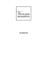
BALANCED
+15 !&its
-
Right
SIgnat
+
Right
SiQ,-&
Shield

Power and Ground
To ensure maximum output from your Tarantula amplifier, use high quality, low-
loss power and ground cables and connections. The Tarantula amplifier will ac-
cept up to l/O gauge power and ground cables.
External
Circuit Breakers and Fuses
Like all audio components, the Tarantula amplifier must be fused near the battery.
A 300 amp fuse or circuit breaker must be located within 18” of the battery. This will
prevent a fire in the event of a shorted cable.
Internal
The Tarantula amplifier is fused with a 300 amp blade-type (ANC) fuse. In the
event of a blown power supply fuse, replace with the correct value fuse.
Never
replace the fuse with a higher value than what is supplied.
This may result in
amplifier damage and will void the warranty!
Remote Turn-On
Connect the turn-on lead from the source unit to the “Remote” input on the ampli-
fier. When
+I2
volts is received, the amplifier will turn on.
Signal Cab/e
Depending on your application, you may use either the DIN audio balanced
signal cable or standard RCA cables to drive your Tarantula amplifier.
Speaker Cable
The Tarantula will accept up to a 4 gauge speaker cable. Use high quality, flexible,
multi-strand cable for best performance and longevity.
9

L’VSTALLA
T7ON
AND
MOUNXNG
AmplifierLocation
The Tarantula amplifier employs highly efficient circuitry, a custom-engineered heat
sink, and a unique
ChassisinkTM
construction to maintain lower operating tempera-
tures. Additional cooling may be required if the amplifier is located in a tightly con-
fined area or when driving especially low impedance loads at extremely high levels.
When mounting the amplifier, it should be securely mounted to a panel in the ve-
hicle or an amp board or rack that is securely mounted to the vehicle. The mount-
ing location should be either in the passenger compartment or in the trunk of the
vehicle, away from moisture, stray or moving objects, and major electrical compo-
nents.
To provide adequate ventilation, mount the amplifier so that there are at least
four inches of freely circulating air above it and at the intake vents on each side of
the amplifier.
a.
b.
C.
a.
b.
C.
d.
Mounting The Amplifier
Using the amplifier as a template, mark the cut out on the mounting surface.
Remove the amplifier and cut out the hole to mount the amplifier.
Secure the amplifier to the mounting surface using the supplied hardware.
Wiring
Run and connect the audio signal and remote turn-on cables to the amplifier
from the source unit.
Carefully’ run the positive cable from the amplifier to a fuse or circuit breaker
within 18” of the battery.
Connect the fuse or circuit breaker lead to the battery. Leave the circuit breaker
off or the fuse out until everything is bolted down.
Secure the ground cable to a solid chassis ground on the vehicle. It may be
necessary to sand paint down to raw metal for a good connection.
Double check each and every connection!
Reconnect the fuse or circuit breaker.
Power Up
Power up the system, there may be a 2-3 second delay from the time the source
unit is turned on to the time that the amplifier turns on, which is normal. Once the
amplifier LED is on and the source unit is playing, you should have sound coming from
the speakers.
10

CRO.S.SOVER
ADJUSTMENTS
The Tarantula amplifier incorporates two separate electronic crossovers. A 12
dB\octave Subsonic filter and an on-board 24 dB/octave electronic low pass cross-
over, with full range RCA outputs to drive an external amplifier. No external elec-
tronic crossover is required when operating this amplifier.
Subsonic
The Subsonic filter allows the amplifier to focus all of its energy where it is needed
most. Adjust the filter to the tuning frequency of a ported box and increases in
output will be noticed immediately. The Subsonic filter is variable from 13 to 30 Hz.
The shaded area below shows the frequency and range adjustments as they ap-
pear on the control panel of the amplifier.
Low Pass
The Low Pass filter is variable from 35 to 500 Hz, which is divided into two separate
ranges: “Low” and “High”. The “Low” range will yield a frequency range from 35 to
135 Hz, while the “High” is from 135 to 500 Hz.
The shaded area below shows the frequency and range adjustments as they ap-
pear on the control panel of the amplifier.
11

HA
WKZNS
BASS CONTROL
-
TffEORY AND USE
Hawkins Bass Control (parametric) is a unique subwoofer control circuit included
with the Tarantula amplifier. It is capable of removing subsonic energy in program
material while boosting subwoofer frequencies. The circuit consists of two con-
trols. One adjusts the frequency of operation and the other adjusts the range of
boost. With both controls adjusted fully counterclockwise, no boost is applied and the
amplifier is flat in response down to 20 Hz.
The frequency control (Hz) adjusts the
starting point of the subsonic filter. On the
Tarantda,
the high pass filter has two fre-
quency ranges. When the bass control
switch is set to “SUBSONIC”, the high pass
filter frequency can be adjusted from 13 Hz
up to a maximum of 30 Hz. In this setting, no
boost “Q” control is available. This control is
useful for setting,the lowest frequency that
your subwoofer will see. When the bass
control switch is set to “HAWKINS BASS
CONTROL”, the high pass filter frequency
can be adjusted from 30 Hz to a maximum
of 70 Hz. In this setting, there is an available
boost control of 0 to
+9
dB.
Fig.1 Variable
“Q”
Fig.2 Variable High Pass
Fig.3 Variable Boost
The Boost control adjusts the level applied at
the set frequency. This is adjustable from flat 0
dB
to
+9
dB
(See figure 1).
When the “Boost” is set to 0, Hawkins acts as a
subsonic filter only (See figure 2). The simple act
of removing potentially harmful
low
frequencies
can
improve system output by as much as 3 dB (See
figure 3).
12

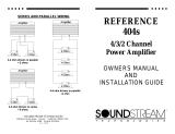
Application
Subwoofers in general have excellent power
’
handling characteristics over their opera-
tional bandwidth. This bandwidth is deter-
mined by
many
factors, including driver de-
dB
-I
sign, and enclosure type. It is possible to
-’
overdrive any subwoofer by sending pow-
:
erful signals outside of its operational band-
0
width. These potentially damaging signals
can be removed by adding a subsonic fil-
Fig.4 Limited Excursion
ter. Figure 4 shows the effectiveness
ofthe
Hawkins Bass Control on woofer excursion in a vented enclosure. The woofer travels
7.5 mm at 10 Hz. With Hawkins Bass Control properly adjusted, this excursion can be
reduced to less than 1 mm. This is of great benefit to lowering woofer distortion and
increasing output.
Adjusfment
An easy method of optimizing your existing subwoofer enclosure with Hawkins “Hz”
control is as follows (assuming the audio system is already turned on).
I.
2.
3.
Adjust frequency and boost control to full counterclockwise position.
Set the bass control switch to “HAWKINS BASS CONTROL”.
While listening to music with strong bass content at a moderate level, slowly adjust
frequency control clockwise. Listen for a reduction of bass response. Now, rotate
frequency control slightly backwards. This serves the purpose of removing the “sub-
sonic” bass energy.
With Soundstream’s Hawkins Bass Control, the boost and frequency control can
provide virtually any combination of boost and cut to suit your designs. So, Hawkins
Bass Control can provide the “tailoring” needed for any type of “assisted” design
and any woofer in any type of installation.
The shaded area below shows the Hawkins Bass Control adjustments, crossover
range switch and frequency as they appear on the control panel of the amplifier.
13

The input level is adjusted by means of the input level control located on the control
panel of the amplifier. This is a unique dual-stage circuit that adjusts both level and
gain. This topology maintains better S/N Ratio even when using sources with minimal
output.
In the ideal situation, all components in the audio system reach maximum undistorted
output at the same time. If you send a distorted signal to an amplifier, it is simply
going to amplify distorted information. The same holds true if an outboard proces-
sor or crossover begins to distort before you have maximum output from the ampli-
fier. By setting all components to reach clipping at the same time, you can maxi-
mize the output of your system.
For the Tarantula, follow these steps for setting
the input levels:
1.
Turn the amplifier’s input level to minimum position (counterclockwise).
2.
Set the source unit volume to approximately
314
of full volume.
3. While playing dynamic source material, slowly increase the amplifier’s input
level until a near maximum undistorted level is heard in the system. This can be
visually
verified
by the input level indicator. The input level light has three levels of
indication; Green (normal), Amber (1
OdB
below clipping), Red (near clipping).
The clipping indicator on the top of the amplifier will let you know when the output
of the amplifier is reaching its maximum level, and has begun to clip.
The shaded area below shows the input and output clip indicators, Large Mouth
Bass switch and input level as they appear on the control panel of the amplifier.
14

LARGE MOUTH BASS
Your Tarantula amplifier comes equipped with a Large Mouth Bass (LMB) remote
volume control. The LMB allows you to adjust the volume of your subwoofers from
the front of the vehicle (or wherever you choose to install it), while not effecting the
volume of the rest of the system.
Wiring
Wiring the LMB is a very easy task. The unit comes with a 20’ cable that has a red,
a white and a black wire inside. As shown below, hook the wires up so that the
numbers and colors are the same on the amplifier and the remote control.
View at Amplifier
View at the Remote Control
Remote Volume Control Knob Installation
The recommended methods for installing the volume control knob are to either
surface or flush mount the unit. After finding an appropriate location in the vehicle,
use the diagrams below to help with the LMB control knob installation.
ISurface
Mount
I
1
Flush Mount
15

POWER SUPPLY
PROGRAMMTAIG
Push Buttons
Momentary Press
(less than half second)
Hold and Release
(more than
haif
second)
!
Power I Calibration
Go to
next
speaker load power level.
4 OHM
(Red)
2 OHM
(Amber)
1 OHM (Green)
Automatically set the power level by
ruming
the speaker load calibration
routine.
:
Illumination
Change
to
next
IigM
mode.
OFF-ON-MUSIC-BLINK
While light is in BLINK mode
change to
next
BLINK rate (8
different rates).
While
IigM
is in OFF I ON I
MUSIC
mode
III”
a polarity
check demo.
TROUBL
E.SHOOli%lG CHART
Condition
Normal
Power LED
Red (4 ohm)
Amber (2 ohm)
Green
(1
ohm)
Status LED
Off
I
I
Red (4 ohm)
Thermal Rollback Amber (2 ohm)
I
Blip
Green 11
ohm)
(on:
0.7
sec.,
off:
1.9
sec.)
Under I Over Battery hput
voltage
I
Fast Blink
(On: 0.05 sec.,
off:
0.1
sec.)
Medium Blink
(On: 0.23 sec.,
oti?
0.1 sec.)
Oil
NOTE:
l At low signal levels the INPUT LEVEL LED is variable green in color.
l With greater signal level the INPUT LEVEL LED begins to appear amber ap-
proximately IOdB below amplifier output clip.
l With extreme signal levels the INPUT LEVEL LED snaps red within 0.5dB of
amp output clip.
l Amplifier output clipping can be identified by a solid red AMP CLIP LED.
l The 1 ohm power level is not a recommended set up for full power output; at
times of reduced volume the 1 ohm power level can be used with actual 2 or 4
ohm speaker loads to save energy draw from the vehicle’s electrical system (i.e.
extend battery life).
16

SAMPLt’
SYSTEM
I
R
R,
I
17

PROliEC7TON
CrRCUrTRY
Your Tarantula is protected against both overheating and short circuits by
means of a main
power
fuse and the following circuits:
+
Under/Over battery input voltage (between 8.5Vdc and
17.OVdc)
+
Speaker Output Protection
+
Ground Fault Differential
+
Variable speed fan cooling with smart power supply thermal rollback
+
Temporary over temperature shutdown with high speed fan cooling
5ERrOU.S
WARNINGS
SER
vrc!?
Your Soundstream
Taranfu/a
is protected by a limited warranty. If an authorized
dealer installs the amplifier, it’s under warranty for a period of three years, a con-
sumer installed unit is warrantied for a period of one year. Please read the en-
closed warranty card for more details and be sure to send it in.
18

SAMPLE SYSTEM
17

PRO
TECTTON
CIRCUITRY
Your
Taranfula
is protected against both overheating and short circuits by
means of a main
power
fuse and the following circuits:
t
Under/Over battery input voltage (between 8.5Vdc and
17.OVdc)
+
Speaker Output Protection
+
Ground Fault Differential
+
Variable speed fan cooling with smart power supply thermal rollback
+
Temporary over temperature shutdown with high speed fan cooling
SERIOUS
WARilKNGS
SER
vrck7
Your Soundstream Tarantula is protected by a limited warranty. If an authorized
dealer installs the amplifier, its under warranty for a period of three years, a con-
sumer installed unit is warrantied for a period of one year. Please read the en-
closed warranty card for more details and be sure to send it in.
18
/