Page is loading ...

PVS4100/4120/4150
Portable Samplers
Revision: 4/12
Copyright © 2011-2012
Campbell Scientific, Inc.


Warranty
The PVS4100/4120/4150 Portable Samplers are warranted for thirty-six (36)
months subject to this limited warranty:
“PRODUCTS MANUFACTURED BY CAMPBELL SCIENTIFIC, INC. are
warranted by Campbell Scientific, Inc. (“Campbell”) to be free from defects in
materials and workmanship under normal use and service for twelve (12)
months from date of shipment unless otherwise specified in the corresponding
Campbell pricelist or product manual. Products not manufactured, but that are
re-sold by Campbell, are warranted only to the limits extended by the original
manufacturer. Batteries, fine-wire thermocouples, desiccant, and other
consumables have no warranty. Campbell's obligation under this warranty is
limited to repairing or replacing (at Campbell's option) defective products,
which shall be the sole and exclusive remedy under this warranty. The
customer shall assume all costs of removing, reinstalling, and shipping
defective products to Campbell. Campbell will return such products by surface
carrier prepaid within the continental United States of America. To all other
locations, Campbell will return such products best way CIP (Port of Entry)
INCOTERM® 2010, prepaid. This warranty shall not apply to any products
which have been subjected to modification, misuse, neglect, improper service,
accidents of nature, or shipping damage. This warranty is in lieu of all other
warranties, expressed or implied. The warranty for installation services
performed by Campbell such as programming to customer specifications,
electrical connections to products manufactured by Campbell, and product
specific training, is part of Campbell’s product warranty. CAMPBELL
EXPRESSLY DISCLAIMS AND EXCLUDES ANY IMPLIED
WARRANTIES OF MERCHANTABILITY OR FITNESS FOR A
PARTICULAR PURPOSE. Campbell is not liable for any special, indirect,
incidental, and/or consequential damages.”

Assistance
Products may not be returned without prior authorization. The following
contact information is for US and international customers residing in countries
served by Campbell Scientific, Inc. directly. Affiliate companies handle
repairs for customers within their territories. Please visit
www.campbellsci.com to determine which Campbell Scientific company serves
your country.
To obtain a Returned Materials Authorization (RMA), contact CAMPBELL
SCIENTIFIC, INC., phone (435) 227-9000. After an applications engineer
determines the nature of the problem, an RMA number will be issued. Please
write this number clearly on the outside of the shipping container. Campbell
Scientific's shipping address is:
CAMPBELL SCIENTIFIC, INC.
RMA#_____
815 West 1800 North
Logan, Utah 84321-1784
For all returns, the customer must fill out a "Statement of Product Cleanliness
and Decontamination" form and comply with the requirements specified in it.
The form is available from our web site at www.campbellsci.com/repair. A
completed form must be either emailed to repair@campbellsci.com or faxed to
(435) 227-9106. Campbell Scientific is unable to process any returns until we
receive this form. If the form is not received within three days of product
receipt or is incomplete, the product will be returned to the customer at the
customer's expense. Campbell Scientific reserves the right to refuse service on
products that were exposed to contaminants that may cause health or safety
concerns for our employees.

i
PVS4100/4120/4150
Table of Contents
PDF viewers: These page numbers refer to the printed version of this document. Use the
PDF reader bookmarks tab for links to specific sections.
1. Product Overview......................................................1-1
1.1 Introduction........................................................................................ 1-1
1.2 Features.............................................................................................. 1-2
1.2.1 PVS4100 and PVS4120 Sampler Features............................... 1-2
1.2.2 PVS4150 Sampler Features...................................................... 1-4
1.2.3 Sampler Vacuum System Features........................................... 1-6
1.2.4 Signal Panel.............................................................................. 1-8
1.3 Specifications..................................................................................... 1-9
1.3.1 PVS4100 Portable Sampler Specifications............................... 1-9
1.3.2 PVS4120 Lightweight Portable Sampler Specifications ........ 1-10
1.3.3 PVS4150 Ultra-Portable Sampler Specifications ................... 1-11
1.3.4 Controller Specifications........................................................ 1-12
1.3.5 Vacuum System Specifications .............................................. 1-13
1.3.6 Sample Container Options...................................................... 1-14
1.3.7 Composite and Discrete Overview......................................... 1-14
1.3.8 Sample Transport Velocity..................................................... 1-15
1.3.8.1 Using Velocity to Calculate Purge Time .................... 1-16
1.3.8.2 Horizontal/Vertical Co
mbinations.............................. 1-16
1.3.9 Special System
s...................................................................... 1-17
1.3.9.1 5/8 Systems................................................................. 1-17
1.3.9.2 MISA Systems – Teflon and Glass............................. 1-17
1.4
Portable Sampler Model Selection Guide ........................................ 1-18
2. Installation .................................................................2-1
2.1 Cabinet Positioning ............................................................................ 2-1
2.2 Intake Hose ........................................................................................ 2-2
2.3 Sinker / Strainer ................................................................................. 2-2
2.4 Storage ............................................................................................... 2-2
2.5 Signal Wiring..................................................................................... 2-3
2.6 Installation Checklist.......................................................................... 2-4
3. Operation ...................................................................3-1
3.1 Operating Sequence ........................................................................... 3-1
3.1.1 Sampling Sequence .................................................................. 3-1
3.1.2 Line Voltage Failure................................................................. 3-2
3.2 Operating Instructions........................................................................ 3-2
3.2.1 Sample Volume Adjustment .................................................... 3-2
3.2.2 Liquid Sensing Rod.................................................................. 3-3
3.3 Battery................................................................................................ 3-4
3.3.1 Battery: Operating and Backup (optional)................................ 3-4
3.3.2 Battery: Microprocessor........................................................... 3-5
3.4 Test Procedure ................................................................................... 3-6
3.5 Troubleshooting ................................................................................. 3-6

PVS4100/4120/4150 Table of Contents
ii
4. Maintenance.............................................................. 4-1
4.1 General Maintenance.......................................................................... 4-1
4.2 Testing System Vacuum..................................................................... 4-1
5. Programming ............................................................ 5-1
5.1 General Programming ........................................................................ 5-1
5.1.1 Guidelines................................................................................. 5-1
5.1.1.1 Flashing Text ................................................................ 5-1
5.1.1.2 Real Time Clock ........................................................... 5-1
5.1.1.3 Total Bottles
.................................................................. 5-1
5.1.2
Touchpad Keys......................................................................... 5-2
5.1.3 General Terms .......................................................................... 5-4
5.2 Quick Start Guide to Programming.................................................... 5-6
5.2.1 Automatic Sampling Program .................................................. 5-6
5.2.2 Taking a Manual Sample .......................................................... 5-7
5.2.3 Viewing Program Parameters ................................................... 5-7
5.2.4 Setting Program Parameters Individually ................................. 5-8
5.3 Programming START DELAY.......................................................... 5-8
5.3.1 START DELAY Overview ...................................................... 5-8
5.3.2 START DELAY using Time/Day ............................................ 5-9
5.3.3 START DELAY using Pulse Input ........................................ 5-11
5.3.4 START DELAY using 4-20mA Input.................................... 5-12
5.3.5 START DELAY using External Contact................................ 5-14
5.3.6 START DELAY using Level Control .................................... 5-15
5.4 Programming SAMPLE INITIATION............................................. 5-16
5.4.1 SAMPLE INITIATION Overview ......................................... 5-16
5.4.2 SAMPLE INITIATION using Interval Time ......................... 5-17
5.4.3 SAMPLE INITIATION using Pulse Input ............................. 5-19
5.4.4 SAMPLE INITIATION using 4-20mA Input......................... 5-20
5.4.5 SAMPLE INITIATION using External Contact .................... 5-22
5.5 Programming PROGRAM TYPE .................................................... 5-23
5.5.1 PROGRAM TYPE Overview................................................. 5-23
5.5.2 PROGRAM TYPE - Composite............................................. 5-24
5.5.3 PROGRAM TYPE - Daily Cycle ........................................... 5-26
5.5.4 PROGRAM TYPE - Daily Cycle for Dual Station ................ 5-27
5.5.5 PROGRAM TYPE - Consecutive........................................... 5-29
5.5.6 PROGRAM TYPE - Multi-Composite................................... 5-31
5.5.7 PROGRAM TYPE - Timed Step............................................ 5-32
5.6 Programming OTHER OPTIONS.................................................... 5-34
5.6.1 OTHER OPTIONS Overview ................................................ 5-34
5.6.2 OTHER OPTIONS - Clock .................................................... 5-36
5.6.3 OTHER OPTIONS - Purge Time ........................................... 5-37
5.6.4 OTHER OPTIONS - Pinch Valve .......................................... 5-39
5.6.5 OTHER OPTIONS - Fault Shutdown .................................... 5-40
5.7 Viewing Information ........................................................................ 5-42
5.7.1 Viewing Programmed Information......................................... 5-42
5.7.2 Viewing Generated Information............................................. 5-44

PVS4100/4120/4150 Table of Contents
iii
Appendices
A. Principles of Operation........................................... A-1
B. Parts List.................................................................. B-1
C.
Programming 4-20mA for Flow Proportional
Sampling ............................................................... C-1
List of Figures
1-1. Highlights of the PVS4100 and PVS4120 Samplers ........................... 1-2
1-2. Highlights of the PVS4150 Sampler.................................................... 1-4
1-3. Diagram of the PVS Vacuum System ................................................. 1-6
2-1. Sampler Installation............................................................................. 2-1
2-2. External Signal Cable for PVS4100 and PVS4120 ............................. 2-3
3-1. Battery Performance Curve ................................................................. 3-4
List of Tables
1-1. PVS4100 and PVS4120 Sampler Features......................................... 1-3
1-2. PVS4150 Sampler Features................................................................. 1-5
1-3. Vacuum System Features .................................................................... 1-7
1-4. PVS4100 Sampler Specifications........................................................ 1-9
1-5. PVS4120 Sampler Specifications...................................................... 1-10
1-6. PVS4150 Sampler Specifications...................................................... 1-11
1-7. Controller Specifications ................................................................... 1-12
1-8. Vacuum System Specifications ......................................................... 1-13
1-9. Sample Container Options – PVS4100 and PVS4120....................... 1-14
1-10. Sample Container Options – PVS4150............................................. 1-14
1-11. Vertical Velocity ............................................................................. 1-15
1-12. Horizontal Velocity ......................................................................... 1-16
1-13. MISA System Changes.................................................................... 1-17
5-1. Touchpad Button Descriptions ............................................................ 5-2
B-1. PVS Replacement Parts ......................................................................B-1

PVS4100/4120/4150 Table of Contents
iv

1-1
Section 1. Product Overview
1.1 Introduction
The PVS4100, PVS4120 and PVS4150 Portable Samplers are automatic liquid
samplers for water and wastewater applications. PVS Samplers are capable of
gathering fluid automatically from a variety of sources, including containers,
open channels, sewers, pipes, and any open source of water.
Samplers are designed for reliable unattended sample collection. Portable units
are capable of keeping the temperature of the deposited liquid at 4ºC (39.2ºF)
for up to 24 hours using crushed ice or ice packs until the samples are gathered
and brought back to the laboratory for analysis.
There are a variety of methods for depositing samples. Composite sampling is
used where samples are deposited, over time, into one container. Discrete
systems are used when multiple bottles are needed. These are also called
“sequential” systems, and involve a stepper with distributor arm which
dispenses the liquid into a bottle, then moves to the next bottle.
Operating temperature for portable samplers is 10ºC to 50ºC (50ºF to 122ºF),
adaptable down to 0ºC (32ºF) upon request.
Samples can be triggered by a variety of means. The internal clock on the
controller can be set to sample based on time/day (e.g. sample every hour).
There are also a variety of external inputs that can be connected to control
sampling using the optional external signal cable. Pulse count is useful for
sampling after a certain number of pulses have been reached (e.g. using a rain
gauge to trigger sampling). The 4-20 mA option is useful for flow-based
sampling (e.g. using a flow meter to trigger sampling after a certain volume of
water has passed by). External contact is used to control the sampler from
another data logger or PLC, and is useful when full external control is desired.
Level control is the option to choose when the application has starts and stops
(e.g. using a float switch to trigger sampling when water is present, then stop
sampling when the water drops below the set level).
When sampling is initiated, liquid travels through the intake tube into the
metering chamber. The amount of water taken is set mechanically using the
liquid sensing rod and the volume control tube, which means sample accuracy
is precise every time, usually within +/- 2% or +/- 2ml.
Once the pre-set amount has been reached, all excess liquid is purged from the
system, and the sample is dropped into a container. Sample containers range
from 500 ml (500 cc or 2 cup) wedges in discrete systems, to 9 liters (2.3
Gallon) containers for composite systems.
Intake tube is offered in either 3/8” (9.5 mm) ID or 5/8” (15.9 mm) ID, and can
be either Nylon-reinforced PVC or Teflon-lined PVC. Transport velocity varies
depending on height and distance being sampled. For most situations the
sampler pulls at over 1.5 m/s (5 ft/sec). For an in-depth speed chart, refer to
Section 1.3.7 Sample Transport Velocity
on page 1-15.

Section 1. Product Overview
1-2
1.2 Features
1.2.1 PVS4100 and PVS4120 Sampler Features
31.875”
(810 mm)
Diameter
16.375”
(416 mm)
2
4
5
1
6
3
8
9
10
11
12
7
13
14
20
19
18
17
15 16
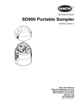
FIGURE 1-1. Highlights of the PVS4100 and PVS4120 Samplers

Section 1. Product Overview
1-3
TABLE 1-1. PVS4100 and PVS4120 Sampler Features
Number Item Description
1 Top Handle For easy transport.
2 Enclosure Molded medium-density linear polyethylene, 3 piece
construction. Provides protection from wind and rain. Not
submersible.
3 Intake Hose Slot The hose must lie in the slot for lid to close properly. A
secondary notch is provided for lining up the sampler properly.
4 Clasps There are three clasps for each section, for a total of six. The
clasps have ringlets for attaching a suspension harness.
5 Signal Panel Red Light: Reverse Polarity, Green Light: Power
Left Plug: External Signals (to be used with optional signal
cable)
Right Plug: Power – 120VAC or 12VDC
Left Fuse: 120VAC, Right Fuse: 12VDC
Toggle Switch: Power On/Off
For detailed chart, see page 1-8.
6 Folding Handles For easy transport.
7 Intake Hose Connection The volume control tube is where the intake hose is connected to
the sampler. This stainless steel tube is raised or lowered
manually using fitting to set the sample volume (see FIGURE 1-3
o
n page 1-6).
8 Wiring Connects electricity to the rods for sampling. When replacing
metering chamber, these rods can be easily disconnected.
9 Nuts to adjust volume To adjust sample volume, twist top nut while holding bottom nut
in place. Hand tightening works for many applications, but a
wrench is advised.
10 Metering Chamber This chamber is where the sample liquid is drawn into before
dropping into the final container. The rods inside are raised and
lowered to the sample volume desired.
11 Battery Standard on all samplers. The PVS4100 battery is 15 lbs, 17AH.
The PVS4120 battery (shown) is 4 lbs, 7 AH.
12 Multi-Function Input Controller This is where sampler is controlled and programmed.
13 Sinker. Optional Strainer. Keeps the end of the intake tube in the source liquid. Optional
strainer can raise collection point above sinker.
14 Intake Hose Standard samplers come with 25 Feet of 3/8” ID PVC tube.
15 Stepper Assembly Moves the distributor arm for multiple bottle configurations. This
is not present on composite (single bottle) samplers.
16 Distributor Arm Dispenses liquid into bottles. Moves to next bottle after
sampling. On composite (single bottle) samplers, this is replaced
with discharge tube.
17 Sample Container(s) The container(s) that the sample is deposited in can be made
from a variety of materials, shapes, and sizes. In discrete
samplers, there is a distributor arm that deposits samples into
multiple containers.
18 Retaining Plate Holds sample bottles down tightly (discrete samplers only).
19 T-Bar This bar is needed to hold the retaining plate down. It is
imperative that the bottles do not lift up even a little bit, as they
can interfere with the mobility of the distributor arm (discrete
samplers only).
20 Bottle-Guide Notch This notch is the location of bottle number one. It lines up the
middle section of the sampler so that the distributor arm can be
placed at the same location.

Section 1. Product Overview
1-4
1.2.2 PVS4150 Sampler Features
1
2
3
4
5
6
7
8
9
10
11
12
14
13
15
16
17
19
18
24.60”
(625 mm)
19.70”
(500 mm)
14.40”
(366 mm)
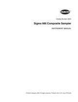
FIGURE 1-2. Highlights of the PVS4150 Sampler

Section 1. Product Overview
1-5
TABLE 1-2. PVS4150 Sampler Features
Number Item Description
1 Signal Panel
Green Light: Integral Battery Charging (AC power connected)
Red Light: External Battery Reverse Polarity
Toggle Switch: Power On/Off
Plug: AC power (coupled with optional signal cable when
supplied).
2 Volume Control Tube
This stainless steel tube is raised or lowered manually using the
fitting to set the sample volume (see FIGURE 1-3 on
page 1-6).
3 Multi-Function Input Controller This is where sampler is controlled and programmed.
4 Metering Chamber
This chamber is where the sample liquid is drawn into before
dropping into the final container. The rods inside are raised and
lowered to the sample volume desired.
5 Pinch Valve
This valve shuts during sampling, and then releases once desired
liquid has entered the chamber.
6 Side Plug
Attached to the side of the door with Velcro. During transport of
full sample container, this plug screws into the hole where the
discharge tube enters the bottle so that the bottle can be carried
upright by its handle.
7 Sample Container
The 2.3 Gal (9L) container that the sample is deposited into is
HDPE, or can be upgraded to PP. Container has a side notch with
plug for discharge tube to enter.
8 Latches
4 Press-and-Pull Latches provide airtight seal of sampler for
transport. Sampler can operate with door open or closed.
9 Cavity Space for Cooling Pack
This space fits one large Zero-Pak cooling pack, to keep sample
cooled for 24 hours.
10 Quick Connectors Optional connectors for quick connecting and disconnecting.
11 Intake Hose Connection
Intake hose is connected to volume control tube in the absence of
quick connectors.
12 LED Indicator Lights
Green light: Power On/Sampling.
Red light: Fault.
13 Enclosure
Hardigg HPX® high performance resin. Enclosure is fully
watertight and submersible, depending on options (check with
factory).
14 Intake Hose Standard samplers come with 25 Feet of 3/8” ID PVC tube.
15 Sinker. Optional Strainer.
Keeps the end of the intake tube in the source liquid. Optional
strainer can raise collection point above sinker.
16 Telescoping Handle
Retractable handle slides up and down for easy transport by
pressing in the small lever on the right side.
17 Side Handles
Four durable soft-grip handles, one on each side, can be folded
up or down.
18 Pressure Gauge
Optional gauge on the side of the enclosure (not shown). This is
helpful for knowing what stage the sampler is at when sampling
with the door closed.
19 Wheels Two wheels for rolling on smooth surfaces.

Section 1. Product Overview
1-6
1.2.3 Sampler Vacuum System Features
FIGURE 1-3. Diagram of the PVS Vacuum System

Section 1. Product Overview
1-7
TABLE 1-3. Vacuum System Features
Number Item Description
1 Solenoid Valves Control the air flow from pump to sampler, either purging or
sucking.
2 Pump Located behind a sheet of metal, the pump does not come into
contact with any liquid whatsoever. It does all the drawing and
purging through using a vacuum and compressor.
3 Touchpad Controller Controls sampler program and offers status feedback on LCD.
4 Sample Distributor Rotates distributor arm between multiple discrete containers.
5 Distributor Arm Dispenses liquid from metering chamber into discrete container.
6 Discrete Sample Containers Multiple containers, always in a quantity divisible into 24
(PVS4100 and PVS4120 only).
7 Pressure Gauge Visually describes sampling process in terms of
vacuum/pressure. Useful for troubleshooting a plugged/kinked
line, or signals leaks. Optional (PVS4150 only).
8 Liquid Sensing Rod This rod must remain above the volume control tube. When the
sample liquid comes into contact with the two rods it signals the
controller to stop sampling and begin purging.
9 Barrier Valve Prevents metering chamber overflow in case the liquid sensing
rod fails (e.g. completely coated with oils/grease).
10 Volume Control Tube Mechanically set the volume required for sample by using a
wrench on the fitting at the base of this stainless steel tube.
11 Metering Chamber Sample is drawn into chamber up to level set by volume control
tube, then line is purged, followed by dropping sample into
containers. Metering Chambers come in glass or acrylic, from
250cc to 500cc.
12 Pinch Valve This valve shuts during sampling, then opens during sampling to
drop sample into container, then closes to purge hose.
13 Cap with “Container Full” Shut-
off
Optional cap contains Overflow Protection Probes which signal
the sampler to halt when container is full. Can be installed in
maximum two containers, or into a discrete bottle tray.
14 Composite Sample Container A single container to hold sample liquid.
15 Intake Hose Standard samplers come with 25 Feet of 3/8” ID PVC tube.
16 Sinker. Optional Strainer. Keeps the end of the intake tube in the source liquid. Optional
strainer can raise collection point above sinker.

Section 1. Product Overview
1-8
1.2.4 Signal Panel
PVS4100 and PVS4120
Red Light: Reverse Polarity, Green Light: Power
Left Plug: External Signals (to be used with optional signal cable)
Right Plug: Power – 120VAC or 12VDC
Left Fuse: 120VAC, Right Fuse: 12VDC
Toggle Switch: Power On/Off
PVS4150
Green Light: Integral Battery Charging (AC power connected)
Red Light: External Battery Reverse Polarity
Toggle Switch: Power On/Off
Plug: AC power (coupled with optional signal cable when supplied).

Section 1. Product Overview
1-9
1.3 Specifications
1.3.1 PVS4100 Portable Sampler Specifications
TABLE 1-4. PVS4100 Sampler Specifications
Dimensions
Height: 809 mm (31.875 in)
Diameter: 428 mm (16.85 in)
Extended Base:
Height: 962 mm (37.875 in)
Diameter: 428 mm (16.85 in)
Weight
(without battery)
11.8 kg (26 lbs)
Enclosure
Molded medium density linear polyethylene, 3 piece
construction, all SS fittings.
Protection Rating: IP 55, Dust protection, water jets.
Power
Requirements
Sampler: DC Output: 13.6V, 10A. AC Input: 88-
264VAC, 50/60Hz, 2.5A (max 3A)
Integral Battery: 12VDC, 17AH, 15 lbs.
External Receptacle: 12 VDC.
Optional AC only model available (no battery).
Cooling System
Insulated container wall. Cavity space for ice.
Operating
Temperature
Standard: 10ºC to 50ºC (50ºF to 122ºF)
* Can be modified to operate down to 0ºC (32ºF) upon
request.
Storage
Temperature
-30ºC to +60ºC (-22ºF to +140ºF)

Section 1. Product Overview
1-10
1.3.2 PVS4120 Lightweight Portable Sampler Specifications
TABLE 1-5. PVS4120 Sampler Specifications
Dimensions
Height: 31.875 in (809 mm)
Diameter: 16.85 in (428 mm)
Extended Base:
Height: 37.875 in (962 mm)
Diameter: 16.85 in (428 mm)
Weight
(without battery)
10.4 kg [23 lbs]
Enclosure
Molded medium density linear polyethylene, 3 piece
construction, all SS fittings.
Protection Rating: IP 55, Dust protection, water jets.
Power
Requirements
Integral Battery: 12 VDC, 7 AH, 4 lbs.
External Receptacle, 12 VDC.
External Charger for 115VAC (optional up to
240VAC).
Optional 120VAC/12VDC power supply with external
battery charger.
Cooling System
Insulated container wall. Cavity space for ice.
Operating
Temperature
Standard: 10ºC to 50ºC (50ºF to 122ºF)
* Can be modified to operate down to 0ºC (32ºF) upon
request.
Storage
Temperature
-30ºC to +60ºC (-22ºF to +140ºF)

Section 1. Product Overview
1-11
1.3.3 PVS4150 Ultra-Portable Sampler Specifications
TABLE 1-6. PVS4150 Sampler Specifications
Dimensions
H: 24.6” x W: 19.7” x D: 14.4”
[H: 625mm x W: 500mm x D: 366mm]
Weight
(without battery)
35.5 lbs [16.1 kg]
Enclosure
HPX high performance resin. Press & Pull latches, and
soft-grip handles.
Protection Rating: IP 67, Dust-tight, water-tight
(depending on options chosen).
Power
Requirements
Integral Battery: 12 VDC, 7 AH, 4 lbs.
External Charger for 115VAC (optional up to
240VAC).
Cooling System
Cavity space for two Zero-Pack (#12396).
Operating
Temperature
Standard: 10ºC to 50ºC (50ºF to 122ºF)
* Can be modified to operate down to 0ºC (32ºF) upon
request.
Storage
Temperature
-30ºC to +60ºC (-22ºF to +140ºF)

Section 1. Product Overview
1-12
1.3.4 Controller Specifications
TABLE 1-7. Controller Specifications
Feature Function Capability
START DELAY
Disabled No start delay.
Time/Day Adjustable, up to 1 week in advance.
Pulse Count Adjustable, up to 9,999,999.
4-20mA Adjustable, up to 9,999,999 (4-20mA = 0-100 Pulses/min).
External Contact Momentary, 25 millisecond dry contact closure.
Level Control Adjustable up to 99 second contact duration.
SAMPLE INITIATION
Disabled No sample initiation.
Interval Time Adjustable up to 999 hours, 99 minutes
Pulse Count Adjustable, up to 9,999,999.
4-20mA Adjustable, up to 9,999,999 (4-20mA = 0-100 Pulses/min).
External Contact Momentary, 25 millisecond dry contact closure.
PROGRAM TYPE
Composite Terminate after up to 9,999,999 samples.
Multi-Composite Adjustable, up to 99 cycles per bottle.
Consecutive Adjustable, up to 9 bottles per cycle.
Daily Cycle Adjustable, up to 9 bottles per day.
Timed Step Adjustable, up to 99 hours, 99 minutes per step.
CLOCK
Real Time Clock Real time operating system.
PINCH VALVE
Sample release Adjustable, normally open / normally closed.
PURGE CYCLE
Draw and purge time Adjustable, 1 to 99 seconds.
SUCTION CYCLE
Variable
Adjusts automatically to double the value of the purge time setting or
until liquid contacts level electrode in metering chamber.
Vacuum
System pressure range is -14 psi to +20 psi, which can be shown on
the Optional Pressure Gauge.
ALARM OUTPUTS
Independent Container Full (Latched. Any key resets. NPN*)
Sample Fault (Latched. Any key resets. NPN*)
Cycle Abandoned (Pulsed. NPN*)
*NPN (sinking) – see Technical Appendix for details.
STATUS OUTPUTS
Independent Sample Taken (DC relay driver, sinking)
DIRECT FUNCTION
KEYS
Manual Sample Samples manually when pressed twice. Does not interrupt program.
Manual Purge Purges system during second press as long as button is pressed.
Manual Bottle Advance Moves distributor arm to next bottle.
Restart Re-initiates program when pressed twice.
AVAILABLE
DISPLAYS
Real-Time Clock
Process Timing Elapsed, remaining.
Process Totals
Pulse Counting Internal/external.
Event Response With time stamp.
Multi-Level
Descriptions
Flashing Text
AUTOMATIC
DISPLAYS
Container Full Sample program complete.
Fault Program not completed.
Power Interrupt –
Program Resumed
Alternating Time Stamp
Cycle(s) Abandoned
/