ENGLISHENGLISHENGLISHENGLISH
Operating instructions
EKS36-2…
EKM36-2…
1 About this document
Please read these operating instructions carefully before using the
EKS36-2 / EKM36-2 safe motor feedback system or mounting it,
putting it into operation or servicing it.
This document is an original document.
1.1 Purpose of this document
These operating instructions are for giving technical personnel of the
machine manufacturer or operator instructions on the safe assembly,
electrical installation, commissioning, operation and maintenance
of the EKS36- / EKM36-2 safe motor feedback system.
In addition, for planning and using protective equipment such as the
EKS36-2 / EKM36-2 safe motor feedback system, technical skills are
required that are not covered by this document.
The ofcial and legal regulations for operating the
EKS36-2 / EKM36-2 safe motor feedback system must always
be complied with.
1.2 Symbols used
a Safety instruction!
A warning indicates a specic or potential hazard.
It is for protecting you from accidents.
Read the safety instructions carefully and follow them.
2 On safety
a Attention!
In addition, observe the safety instructions and warnings
in the documentation of the drive system connected.
2.1 Skilled persons
The EKS36-2 / EKM36-2 safe motor feedback system may be mounted,
put into operation, checked, serviced and used by skilled persons only.
A skilled person
▸
has taken part in adequate technical training
and
▸
has been instructed by the machine operator in machine operation
and the applicable safety guidelines
and
▸
can access these operating instructions.
2.2 Field of use for the device
The safety-related use of the EKS36-2 / EKM36-2 safe motor feedback
system with a HIPERFACE DSL
®
interface applies to its use in combina-
tion with servo systems with three-phase AC synchronous motors. Their
commuting information and (rotational) speed information is derived
from the digital position signals of the encoder connected directly to
the motor shaft. Alternatively it is possible to use the system on asyn-
chronous motors, the speed or speed information of which is derived
directly from the digital position signals of the encoder which
is coupled directly to the motor shaft.
The EKS36-2 / EKM36-2 safe motor feedback system can be used in
combination with a drive system as per IEC 61800-5-2, for safety
applications up to control category 3 as per EN ISO 13849, SILCL2
as per EN 62061 or up to PL d as per EN ISO 13849.
It meets the requirements of machinery directive 2006 / 42 / EC and
is for supporting the drive system in ensuring
▸
the safety functions, based on the reliable position or speed
information of the motor feedback system
▸
the motor feedback system has only one channel for safety-oriented
diagnosis for safety functions that are based on the absolute positi-
on. A second channel must be established by the user with the help
of other measures. Without a second channel, every time the motor
feedback system is activated a reference traverse must be done in
order to confirm the absolute position.
2.3 Intended use
The safe motor feedback system may be used only in terms of the
“Scopes of application of the device” chapter and within the limits of
the prescribed and specied technical data, dimensions and toleran-
ces of the dimensional drawings and operating conditions, and the
specied tightening torques must be complied with.
It is especially important that the motor feedback system not be used
for safety applications beyond its mission time and bearing service life
(see technical data). After its bearing service life is exceeded, bearing
wear or fatigue could lead to bearing failure.
To prevent this, the motor feedback system must be taken out of ope-
ration no later than when the bearing service life has been reached.
The bearing service life is also inuenced by the specic application, in
particular due to operating modes with low speeds, reversing operation
and mechanical vibrations. Current should be prevented from passing
through the ball bearing (e.g. due to injected currents).
If used in any other way or if alterations are made to the device
– including in the context of assembly and installation – this will render
warranty claims void directed to SICK STEGMANN GmbH.
2.4 General safety instructions and
protective measures
a Safety instructions!
Observe the following to ensure the safe use of the EKS36-2 /
EKM36-2 safe motor feed back system as intended.
▸
The national and international legal specifications apply to the
installation and use of the EKS36-2 / EKM36-2 safe motor feedback
system, to its commissioning and to technical inspections repeated
at regular intervals, in particular:
▸
the machinery directive 2006 / 42 / EC
▸
the use of work equipment directive 2009 / 104 / EC
▸
the accident prevention regulations and safety regulations
▸
and any other relevant safety regulations
▸
The manufacturer and operator of the machine on which the EKS36-2 /
EKM36-2 safe motor feedback system is used are responsible for
coordinating and complying with all applicable safety specifications
and regulations, in cooperation with the relevant authorities.
▸
The manufacturer of the drive system connected must have
complied with the safety requirements for the drive system design
described in the implementation manual, “HIPERFACE DSL
®
Safety”.
▸
These operating instructions must be made available to the operator
of the machine on which the EKS36-2 / EKM36-2 safe motor feedback
system is used. The machine operator must be instructed by skilled
personnel and read the operating instructions.
2.5 Associated documents
▸
“HIPERFACE DSL
®
” interface manual,
order number 8017595, as of 05.2014 (or newer)
▸
“Hiperface DSL
®
” implementation manual,
order number 8017596, as of 05.2014 (or newer)
2.6 Maintenance and repair
The EKS36-2 / EKM36-2 safe motor feedback system is maintenance-free.
It is not designed to be repaired if defective.
Please contact us if you have any complaints.
2.7 Disposal
▸
Always dispose of unusable or irreparable devices in accordance
with the applicable specific national waste disposal regulations.
Note
We will be glad to assist you in the disposal of these devices.
Please contact us.
3 Product description
Type EKS36-2 / EKM36-2 encoders are motor feedback systems
predestined for the dynamic and precise operation of servo-control
circuits, due to their equipment.
The overall system, consisting of encoder, evaluation system, servo
inverter and motor, forms a control circuit. Actual values for commu-
tation, rotational speed, direction of rotation and position are derived
from the encoder signals. Encoder systems of the EKS36-2 / EKM36-2
series are suitable for use in function chains of safety-related machine
functions.
The sensor signals are transferred to the evaluation system via HIPERFACE
DSL
®
interface. In combination with a drive system of category 3 (EN ISO
13849), SILCL2 (EN 62061) or PL d (EN ISO 13849), the motor feedback
system is suitable for safety applications. For position and speed-based
safety functions of the drive, the motor feedback system meets the requi
-
rements in EN 61800-5-2.
4 Assembly
a Safety instructions!
Observe the following for assembly of the EKS36-2 / EKM36-2
safe motor feedback system.
▸
Switch off the power of all affected machines / units during the
assembly process.
▸
Make sure to avoid any blows or impact to the shaft under all
circumstances, to prevent damage to the ball bearings.
▸
For EKS36-2 / EKM36-2 encoders with tapered shaft
the shaft end of the motor may only have a diameter of 12 mm max.
4.1 Preparation for mounting
Degrease the drive shaft and the shaft of the motor feedback system.
4.1.1 Erforderliche Werkzeuge / Teile
The assembly tool BEF-MW-EKX36 (part no. 2060224)
is required for mounting or removing.
Two DIN cheese-head / oval-head screws M3 are required for assembly.
4.1.2 Generally Applicable Notes
Using the torque support for the motor feedback system, the housing
must be correctly seated in the customer's ange arrangement.
The more precise the centering for the motor feedback system, the less
the angle and shaft offset during assembly and the less load on the
bearings of the motor feedback system.
EMC considerations make it mandatory to connect the housing and /
or the encoder to earth. For the EKS36-2 / EKM36-2 with tapered
shaft, this is provided by the torque support.
a Shielding connection
To ensure trouble-free operation, it is imperative to ensure
suitable shield connection of the motor.
4.2 Assembling the motor feedback
system with tapered shaft and
spring plate support (Fig. 4)
▸
Block customer's drive shaft to prevent rotation.
▸
The hexagonal part (1) of the encoder shaft (2) must be engaged
in the recess of the fixing plate (3) of the torque support (4). Place
the assembly tool (5) on the back of the encoder and engage in the
recesses of the encoder housing (6). Using the hexagonal part (7)
of the assembly tool (5), screw the encoder into the drive shaft.
Screws (8) must not hook into the fixing holes of the motor.
Tightening torque: 4 Nm + 0.8 Nm.
a Observe the tightening torque!
Compliance with the tightening torque attains an oversizing of
the friction-lock shaft connection that justies the supposition
of fault exclusion in regard of a “break in the motor / encoder
shaft connection”.
a Safety instruction!
Make sure that assembly work is only performed and docu-
mented by appropriately i nstructed and trained personnel.
▸
Release the drive shaft and rotate the encoder until the holes in
the fixing plate (3) are positioned over the fixing holes of the motor
flange. Alternately tighten the fixing plate (3) with 2 M3 screws (8)
on the motor flange. This releases the encoder shaft.
Fastening torque: 0.8 Nm ± 0.08 Nm.
Attention!
▸
The internal thread in the motor shaft must be free of burrs and dirt.
▸
The taper must be free of dirt and grease.
▸
Max. torque for the tapered shaft thread, before the taper
is seated: 0.8 Nm.
Dismantling:
▸
Block customer's drive shaft to prevent rotation.
▸
Open the cover (12) using a screwdriver if necessary (Fig. 4).
Remove the connector fitted with the set of strands (9 + 10) volt-free
▸
Remove the 2 M3 screws (8). The fixing plate (3) is to be positioned
in such a way that the screw holes are aligned with the torque
support (4). Turn the encoder by hand until fixing plate (3) engages.
Place the assembly tool (5) on the back of the encoder and engage
in the recesses of the encoder housing (6). Using the hexagonal
part (7) of the assembly tool (5), detach and remove the encoder
from drive shaft.
5 Electrical installation
a Safety instructions!
Observe the following for electrical installation of the EKS36-2 /
EKM36-2 safe motor feedback system.
▸
To connect the sensors, refer to the corresponding operating instruc-
tions for the external drive system or for the higher-order control system.
The supply voltage has to be generated by PELV systems (EN 50178).
The motor feedback system corresponds to protection class III accor-
ding DIN EN 61140. If the supply voltage is not generated by the PELV
systems, other measures must be found that will guarantee that mains
supply voltage parts are safely separated
▸
Never establish or remove electrical connections to the motor
feedback system with the power connected, since that could result
in a faulty device.
5.1 Interface connection
▸
Open the cover (12) using a screwdriver if necessary (Fig. 4).
Engage the connector (9) fitted with the set of strands (10), volt-free,
in the connector socket (11) of the encoder.
▸
Close the cover (engage in the recess of the encoder housing (6)).
▸
The engagement by clicking must be clearly felt or heard.
May be difficult to close with your bare hands.
Use tools if necessary.
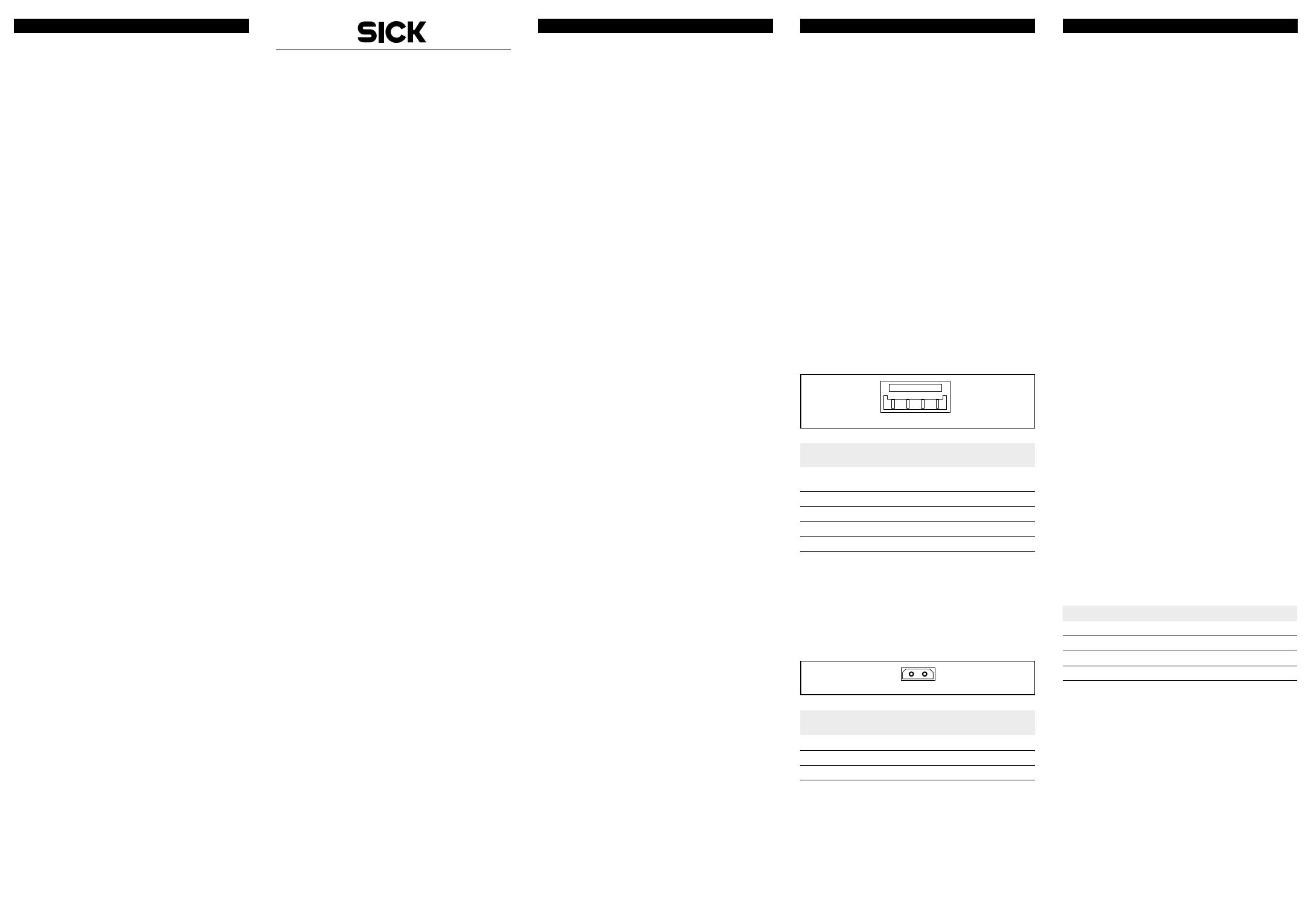
Fig. 1: In-line plug connection, 4-pin
Table 1. 2-pin interface PIN assignment
5.2 Temperature sensor connection
(only variants EKS36-2K, EKM36-2K)
Plug the temperature sensor (13) into the connector socket (14)
volt-free.
a Safety instructions!
Since there is no electrical isolation of the temperature sensor
in the motor feedback system, only temperature sensors with
double or reinforced isolation may be used.
Fig. 2: 2-pin sensor plug pin assignment
Table 2. 2-pin sensor plug PIN assignment
5.3 Signals of the encoder system
1234
PIN and conductor assignment EKS36-2J /
EKM36-2J / EKS36-2K / EKM36-2K
PIN Signal Cable color
(cable outlet)
1 n. c. –
2 +U
S
/ DSL+ gray
3 GND / DSL– green
4 housing cable shield
PIN and conductor assignment
EKS36-2K / EKM36-2K
PIN Signal
1 T+
2 T– / GND
The EKS36-2 / EKM36-2 safe motor feedback system provides the
following signals via HIPERFACE DSL
®
interface:
▸
+U
S
/ DSL+; Supply voltage to the encoder with modulated positive
data signal. The operating voltage range of the encoder is between
+7 V and +12 V.
▸
GND / DSL–; Encoder ground connection with modulated negative
data signal. The operating voltage range of the encoder is between
+7 V and +12 V.
▸
Housing: to connect cable shield to housing potential
▸
T+; Sensor signal for passive temperature sensor / temperature
resistance.
▸
T- / GND: Ground reference for passive temperature sensor /
temperature resistance sensor signal.
6 Commissioning
To commission the safe motor feedback system, EKS36-2 /EKM36-2,
it is assumed that the manufacturer of the connected drive system has
complied with the safety requirements for the drive system design, as
described in the implementation manual, “HIPERFACE DSL
®
Safety”.
6.1 Inspection instructions
▸
When commissioning, ensure that a safe EKS36-2 /EKM36-2 motor
feedback system is used and not an EKS36-0 / EKM36-0 standard
motor feedback system. This must be verified by reading out the
type name (resource 083h). In addition this must be verified by
sending off at least one test message (see “HIPERFACE DSL
®
Safety”
implementation manual).
▸
When changing the position offset of the motor feedback system
via the resource 101h (“Set position”) or 108h (“Factory settings”),
you must subsequently verify that the sensor is delivering the desired
positional value.
Further inspection measures are not required during operation.
a Warning!
Observe the service life!
The EKS36-2 / EKM36-2 safe motor feedback systems have a
specied maximum service life, after which they must always
be taken out of service.
The bearing service life must be taken into account in addition
to the mission time. The parameter which is rst reached
depending on the application determines the time when the
system must be taken out of operation.
The year of manufacture of the motor feedback system is specied on
the device label and / or packaging label using a four digit code (yyww).
The rst two digits yy specify the year (without the century), the last two
digits ww specify the calendar week of the last manufacturing process.
The EKS36-2 / EKM36-2 safe motor feedback systems issue a warning
message when their service life has expired.
6.2 Declaration of conformity
The EKS36-2 / EKM36-2 safe motor feedback system family was
manufactured in accordance with the following directives:
– the machinery directive 2006 / 42 / EC
– the EMC directive 2014 / 30 / EU
The complete EU declaration of conformity is
available at the SICK homepage on the Internet:
www.sick.com
7 Order data
Type Item no.
EKS36-2KF0B018A 1084231
EKS36-2KF0B020A 1084232
EKM36-2KF0B018A 1084235
EKM36-2KF0B020A 1084236
EKS36-2…
EKM36-2…
Sichere Motor-Feedback-Systeme
SICK STEGMANN GmbH
Postfach 1560 · D-78156 Donaueschingen
Dürrheimer Straße 36 · D-78166 Donaueschingen
Telefon: +49 771 80 70 · Telefax +49 771 80 71 00
BZ int46
Please find detailed addresses and further locations in all major industrial
nations at www.sick.com
Australia
Phone +61 3 9457 0600
Austria
Phone +43 22 36 62 28 8-0
Belgium/Luxembourg
Phone +32 2 466 55 66
Brazil
Phone +55 11 3215-4900
Canada
Phone +1 905 771 14 44
Czech Republic
Phone +420 2 57 91 18 50
Chile
Phone +56 2 2274 7430
China
Phone +86 20 2882 3600
Denmark
Phone +45 45 82 64 00
Finland
Phone +358-9-2515 800
France
Phone +33 1 64 62 35 00
Germany
Phone +49 211 5301-301
Hong Kong
Phone +852 2153 6300
Hungary
Phone +36 1 371 2680
India
Phone +91 22 4033 8333
Israel
Phone +972 4 6881000
Italy
Phone +39 02 274341
Japan
Phone +81 3 5309 2112
Malaysia
Phone +6 03 8080 7425
Mexico
Phone +52 472 748 9451
Netherlands
Phone +31 30 2044 000
New Zealand
Phone +64 9 415 0459
Norway
Phone +47 67 81 50 00
Poland
Phone +48 22 539 41 00
Romania
Phone +40 356 171 120
Russia
Phone +7 495 775 05 30
Singapore
Phone +65 6744 3732
Slovakia
Phone +421 482 901201
Slovenia
Phone +386 591 788 49
South Africa
Phone +27 11 472 3733
South Korea
Phone +82 2 786 6321
Spain
Phone +34 93 480 31 00
Sweden
Phone +46 10 110 10 00
Switzerland
Phone +41 41 619 29 39
Taiwan
Phone +886 2 2375-6288
Thailand
Phone +66 2645 0009
Turkey
Phone +90 216 528 50 00
United Arab Emirates
Phone +971 4 88 65 878
United Kingdom
Phone +44 1727 831121
USA
Phone +1 800 325 7425
Vietnam
Phone +84 945452999
Subject to change without notice.
8020309/10RG/2018-08-16 CW_07

