Page is loading ...

D200-72-00 1 I56-1184-008R
FTX-P1 Filtrex
®
Intelligent
Photoelectronic Smoke Detector
INSTALLATION AND MAINTENANCE INSTRUCTIONS
3825 Ohio Avenue, St. Charles, Illinois 60174
1-800-SENSOR2, FAX: 630-377-6495
www.systemsensor.com
Before Installing
This detector must be installed in compliance with the con-
trol panel system installation manual. The installation must
meet the requirements of the Authority Having Jurisdic-
tion (AHJ). Detectors offer maximum performance when
installed in compliance with the National Fire Protection
Association (NFPA); see NFPA 72.
General Description
Filtrex® uses a small air intake fan and a high density re-
placeable filter. Air and smoke are drawn into a photoelec-
tric sensing chamber while airborne particulate and water
mist are removed. The addressable-analog detector transmits
an analog representation of smoke density over a commu-
nication line to a control panel. Rotary-decade switches are
provided for setting the sensor’s address. Two LEDs on the
sensor are controlled by the panel to indicate sensor status.
Filtrex smoke detector is intended for use in normal en-
vironmental conditions, where dust and other airborne
particulate are present at elevated levels. These elevated
levels tend to cause false alarms and high maintenance
in standard detectors. Filtrex provides a protective en-
closure for a photoelectric smoke detector chamber and
allows smoke detection in areas that tended to use exclu-
sively heat detection.
Filtrex requires compatible addressable communications
to function properly. Connect this detector to listed-com-
patible control panels only.
Spacing
System Sensor recommends spacing detectors in com-
pliance with NFPA 72. In low air flow applications with
smooth ceilings, space detectors 30 feet apart. For specific
information regarding sensor spacing, placement, and spe-
cial applications, refer to NFPA 72 or the System Sensor
Guide For Proper Use of System Smoke Detectors, available
from System Sensor (P/N I56-407-XX).
WARNING
Filtrex is not designed to operate in explosive environments.
Specifications
Operating Voltage Range: 15 to 32 VDC
Detector Current: 250 µA @ 24 VDC (without communication)
360 µA @ 24 VDC (one communication every 99 communications with LED enabled)
Auxiliary Power Supply Voltage: 15 to 30 VDC filtered; Ripple voltage may not drop below 15 volts.
Auxiliary Power Supply Current:
Peak: 123 mA max.
Average: 27 mA max.
Operating Humidity Range: 10% to 93% Relative Humidity, noncondensing
Operating Temperature Range: 0°C to 50°C (32°F to 122°F)
Height: 2.8 inches (43 mm)
Diameter: 6.1 inches (155 mm) installed in B501B-FTX
4.0 inches (102 mm) installed in B524FTXE
Weight: 7.3 oz. (207 g)
Compatibility: Backwards compatible with 200 and 500 series products’ protocol
Mounting Base: Requires B501B-FTX (U.S.), B524FTXE (Europe)
C0193-00

D200-72-00 2 I56-1184-008R
Wiring Instructions
All wiring must be installed in compliance with the National
Electrical Code, applicable local codes, and any special re-
quirements of the Authority Having Jurisdiction. Proper
wire gauges should be used. The installation wires should
be color-coded to limit wiring mistakes and ease system
troubleshooting. Improper connections will prevent a sys-
tem from responding properly in the event of a fire.
Remove power from the communication line before install-
ing detectors.
All wiring must conform to applicable local codes, ordi-
nances, and regulations.
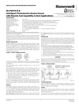
1. Wire the sensor base per the wiring diagram, please see Figure 1.
2. Set the desired address on the sensor address switches,
please see Figure 2.
3. Insert 5-wire connector on mounting base into 5-pin
connector on Filtrex unit. Install the detector into the
sensor base. Push the detector into the base while turn-
ing it clockwise to secure it in place. (Please see Figure
5 and INSTALLING FILTREX INTO BASE on page 4 for
specific directions.
4. After all detectors have been installed, turn on the auxil-
iary power supply, then apply power to the control unit
and activate the communication line.
5. Test the detector(s) as described in the TESTING section
of this manual.
CAUTION
Dust cover must be removed before the detector can sense smoke.
LISTED COMPATIBLE CONTROL PANEL
AUX.
POWER
SUPPLY
+
+
–
–
A
UX
+
AUX
–
A
UX
+
AUX
–
2
(
–
)
3(
R
A)
4(S)
1
(
+)
1
(+
)
2(
–
)
3(R
A
)
4(
S
)
Testing
Before testing, notify the proper authorities that the system
is undergoing maintenance, and will temporarily be out of
service. Disable the system to prevent unwanted alarms.
All detectors must be tested after installation and periodi-
cally thereafter. Testing methods must satisfy the Authority
Having Jurisdiction (AHJ). Detectors offer maximum per-
formance when tested and maintained in compliance with
NFPA 72.
The sensor can be tested in the following ways:
A. Functional: Magnet Test (P/N M02-04-01 or M02-09-00)
This detector can be functionally tested with a test mag-
net. The test magnet electronically simulates smoke in
the sensing chamber, testing the detector electronics and
connections to the control panel.
1. Hold the test magnet in the magnet test area as
shown in Figure 3.
2. The detector should alarm the panel. Two LEDs
on the detector are controlled by the panel to indi
cate sensor status. Coded signals, transmitted from
the panel, can cause the LEDs to blink, latch on, or
latch off. Refer to the control panel technical doc
umentation for detector LED status operation and
expected delay to alarm.
B. Smoke Entry: Aerosol Generator
Aerosol generators for smoke entry testing are available
from a number of third party manufacturers (e.g., Gem-
ini Scientific). Following the manufacturer’s instruc-
tions, apply aerosol until the panel alarms.
Figure 1. Wiring diagram:
C0121-00

D200-72-00 3 I56-1184-008R
TEST MAGNET
MARKER
Cover is keyed to fit
into 4 matching
size slots.
Alignment marks are
provided on the cap
and top of the
permanent filter.
TENS ONES
9
8
7
6
5
4
3
2
1
0
9
8
7
6
5
4
3
2
1
0
C0146-00
Figure 2. Rotary decade address switches:
Figure 3. Test magnet position:
Figure 4. Replacing the filter cover:
A detector that fails any of these tests should be retested.
If the detector still fails any test, have its filter replaced
(see instructions below) and retested. Finally, if the detec-
tor continues to fail after replacing the filter, it must be re-
turned for repair or replacement.
When testing is complete, restore the system to normal op-
eration and notify the proper authorities that the system is
back in operation.
Cleaning
The unique design of Filtrex eliminates the need for typi
-
cal detector cleaning. The only maintenance necessary is
replacing the filter, which is signaled by a trouble condition
at the panel (see below).
Filtrex has been designed to maximize the amount of time
before maintenance is required. Filtrex utilizes a replaceable
filter that may become clogged over time. Filtrex monitors
itself to insure that the filter has not become clogged. Be-
cause environmental conditions can vary significantly, the
amount of time before maintenance could vary significantly
as well. To fully understand the maintenance requirements
of Filtrex in its installed location, it is recommended that
the following test program be conducted.
1. Install Filtrex in the desired location.
2. Connect Filtrex to the fire alarm control panel.
3. Maintain a record for at least 90 days of any mainte-
nance performed on or required by Filtrex.
4. At the end of the test period, use the record to develop
and schedule maintenance. Filtrex detectors should be
serviced at regular intervals to insure that the fire alarm
system provides continuous protection.
Replacing the Filter
IMPORTANT: When the filter becomes too clogged to draw
adequate air into Filtrex, power is automatically cut from
the detector, sending a trouble signal to the fire control
panel. After 5 minutes, power is restored to the detector for
72 hours. After 72 hours, power is cut again and the detec-
tor will remain off-line until the filter is replaced.
NOTE: The unit has two filters. The replaceable filter is
inside the cover. A permanent filter is mounted
to the unit.
1. Grasp the Filtrex housing with one hand and the cover
with the other. Turn the cover counterclockwise fully
(approx. 30 degrees) and remove cover by pulling it
away from detector unit (see Figure 4).
2. Replace with new filter and cover assembly. The cover
is keyed so it fits in place only one way. Turn the cover
clockwise until it stops.
NOTE:
The base is equipped with an optional tamper proof
feature which can be used to prevent unintentional removal
of Filtrex while replacing the filter.
C0191-00
C0192-00

D200-72-00 4 I56-1184-008R
© 2005 System Sensor
System Sensor warrants its enclosed air duct smoke detector to be free
from defects in materials and workmanship under normal use and ser
-
vice for a period of three years from date of manufacture. System Sensor
makes no other express warranty for this air duct smoke detector. No
agent, representative, dealer, or employee of the Company has the author-
ity to increase or alter the obligations or limitations of this Warranty. The
Company’s obligation of this Warranty shall be limited to the replacement
of any part of the air duct smoke detector which is found to be defec-
tive in materials or workmanship under normal use and service during
the three year period commencing with the date of manufacture. After
phoning System Sensor’s toll free number 800-SENSOR2 (736-7672) for
a Return Authorization number, send defective units postage prepaid to:
Figure 5: Installing Filtrex detector into base:If a clogged filter was the cause of the trouble condition,
normal detector operation should resume automatically
within five minutes. If the trouble condition persists, the
detector must be returned for repair or replacement.
Installing Filtrex Into Base
1. Align the detector at a right angle to the base, with the
five wires and connector adjacent to the connector re-
ceptacle as shown in Figure 5.
2. Plug the wired connector into the receptacle.
3. Rotate the detector into the base, making sure detector
and base keyed fit is lined up. Turn the detector clock-
wise until it snaps into place.
IMPORTANT: Filtrex will only operate with B501B-FTX/
B524FTXE Mounting Base.
Special Note Regarding Smoke Detector Guards
Smoke detectors are not to be used with detector guards
unless the combination has been evaluated and found
suitable for that purpose.
FCC Statement
This device complies with part 15 of the FCC Rules. Operation is subject to the following two conditions: (1) This device may not cause harmful interference, and (2) this
device must accept any interference received, including interference that may cause undesired operation.
NOTE: This equipment has been tested and found to comply with the limits for a Class B digital device, pursuant to Part 15 of the FCC Rules. These limits are designed to
provide reasonable protection against harmful interference in a residential installation. This equipment generates, uses and can radiate radio frequency energy and, if not
installed and used in accordance with the instructions, may cause harmful interfer-ence to radio communications. However, there is no guarantee that interference will not
occur in a particular installation. If this equipment does cause harmful interference to radio or television reception, which can be determined by turning the equipment off
and on, the user is encouraged to try to correct the interference by one or more of the following measures:
– Reorient or relocate the receiving antenna.
– Increase the separation between the equipment and receiver.
– Connect the equipment into an outlet on a circuit different from that to which the receiver is connected.
– Consult the dealer or an experienced radio/TV technician for help.
Three-Year Limited Warranty
System Sensor, Returns Department, RA #__________, 3825 Ohio Avenue,
St. Charles, IL 60174. Please include a note describing the malfunction and
suspected cause of failure. The Company shall not be obligated to replace
units which are found to be defective because of damage, unreasonable
use, modifications, or alterations occurring after the date of manufacture.
In no case shall the Company be liable for any consequential or incidental
damages for breach of this or any other Warranty, expressed or implied
whatsoever, even if the loss or damage is caused by the Company’s neg
-
ligence or fault. Some states do not allow the exclusion or limitation of
incidental or consequential damages, so the above limitation or exclusion
may not apply to you. This Warranty gives you specific legal rights, and
you may also have other rights which vary from state to state.
0845
SYSTEM SENSOR
3825 OHIO AVENUE, ST. CHARLES,
IL, 60174 8021 U.S.A.
0845-CPD-232.1427
EN54-7: 2000
MODEL FTX-P1
Filtrex Point Optical Smoke Sensor for Harsh Areas
0845
Please refer to insert for the Limitations of Fire Alarm Systems
/